Table of Contents
Advertisement
Quick Links
www.ti.com
EVM User's Guide: REF54EVM
REF54 Evaluation Module
Description
The REF54EVM is a precision voltage reference
evaluation module that demonstrates the performance
of high precision series reference device (REF54)
from Texas Instruments (TI). The
of high precision, low drift, low current consumption
series voltage reference devices. The REF54 family
offers low temperature drift coefficient (0.5 ppm/°C),
low flicker noise (0.16 ppm p-p with 100uF capacitor
on NR pin) and high accuracy (±0.02%),while
consuming 260 μA current.
Get Started
1. Order the EVM at ti.com.
2. Configure EVM jumpers (if required).
3. Connect VIN and EN (optional) to power supplies.
4. Test the output.
SNAU289 – AUGUST 2023
Submit Document Feedback
Features
•
•
REF54
is a family
Applications
•
•
•
•
•
•
•
•
•
•
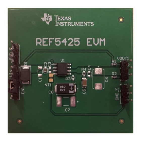
REF54EVM Board
Copyright © 2023 Texas Instruments Incorporated
Enable and disable the output
Capacitor at NR pin is configurable with 0 ohm
resistor to optimize the noise performance
Semiconductor test equipment
Precision data acquisition systems
Precision weight scales
Ultrasound scanner
X-ray systems
Industrial instrumentation
PLC analog I/O modules
Field transmitters
Power monitoring
Battery management system
Description
REF54 Evaluation Module
1
Advertisement
Table of Contents

Subscribe to Our Youtube Channel
Related Manuals for Texas Instruments REF54EVM


Summary of Contents for Texas Instruments REF54EVM
- Page 1 Description EVM User's Guide: REF54EVM REF54 Evaluation Module Description Features The REF54EVM is a precision voltage reference • Enable and disable the output evaluation module that demonstrates the performance • Capacitor at NR pin is configurable with 0 ohm...
-
Page 2: Kit Contents
Texas Instruments integrated circuits used in the assembly of the REF54EVM. This user's guide is available from the TI web site under literature number SNAU289. Any letter appended to the literature number corresponds to the document revision that is current at the time of the writing of this document. - Page 3 REF54250CDR VREF Figure 2-1. REF54 EVM Setup The REF54EVM is designed to allow users to evaluate the configuration shown in Figure 2-1. Multiple footprints are provided for passive input, output and NR pin capacitors, so that the user can change the passive components for best performance in the application.
-
Page 4: Jumper Information
Hardware www.ti.com 2.2 EVM Connection The headers of REF54EVM are named similar to pin name of REF54250CDR for easy understanding. Default EVM setup is shown in Figure 2-2. Input power supply must be connected between VIN1 and GND1 header. Pin 2 of EN1 header can be connected to power supply directly or pin 1 of EN1 header to enable the device. - Page 5 Output voltage of REF54 is measured with dropout conditions meets the initial accuracy and temperature drift spec limit. Device meets line regulation spec and shutdown condition for relevant tests. SNAU289 – AUGUST 2023 REF54 Evaluation Module Submit Document Feedback Copyright © 2023 Texas Instruments Incorporated...
- Page 6 Hardware Design Files www.ti.com 4 Hardware Design Files 4.1 Schematics The schematic for the REF70EVM is illustrated in Figure 3-3 Figure 4-1. REF54 EVM schematic REF54 Evaluation Module SNAU289 – AUGUST 2023 Submit Document Feedback Copyright © 2023 Texas Instruments Incorporated...
-
Page 7: Pcb Layouts
Hardware Design Files 4.2 PCB Layouts REF54EVM is a two layer board. The layout is illustrated in this section. Figure 4-2. REF54EVM Top Layer SNAU289 – AUGUST 2023 REF54 Evaluation Module Submit Document Feedback Copyright © 2023 Texas Instruments Incorporated... - Page 8 Hardware Design Files www.ti.com Figure 4-3. REF54EVM Bottom Layer REF54 Evaluation Module SNAU289 – AUGUST 2023 Submit Document Feedback Copyright © 2023 Texas Instruments Incorporated...
-
Page 9: Additional Information
TSW-102-07-G-S Samtec Gold, TH 5 Compliance Information 5.1 Compliance and Certifications REF54EVM EU Declaration of Conformity (DoC) for Restricting the Use of Hazardous Substances (RoHS) (SSZQR85). 6 Additional Information 6.1 Trademarks All trademarks are the property of their respective owners. - Page 10 STANDARD TERMS FOR EVALUATION MODULES Delivery: TI delivers TI evaluation boards, kits, or modules, including any accompanying demonstration software, components, and/or documentation which may be provided together or separately (collectively, an “EVM” or “EVMs”) to the User (“User”) in accordance with the terms set forth herein.
- Page 11 www.ti.com Regulatory Notices: 3.1 United States 3.1.1 Notice applicable to EVMs not FCC-Approved: FCC NOTICE: This kit is designed to allow product developers to evaluate electronic components, circuitry, or software associated with the kit to determine whether to incorporate such items in a finished product and software developers to write software applications for use with the end product.
- Page 12 www.ti.com Concernant les EVMs avec antennes détachables Conformément à la réglementation d'Industrie Canada, le présent émetteur radio peut fonctionner avec une antenne d'un type et d'un gain maximal (ou inférieur) approuvé pour l'émetteur par Industrie Canada. Dans le but de réduire les risques de brouillage radioélectrique à...
- Page 13 www.ti.com EVM Use Restrictions and Warnings: 4.1 EVMS ARE NOT FOR USE IN FUNCTIONAL SAFETY AND/OR SAFETY CRITICAL EVALUATIONS, INCLUDING BUT NOT LIMITED TO EVALUATIONS OF LIFE SUPPORT APPLICATIONS. 4.2 User must read and apply the user guide and other available documentation provided by TI regarding the EVM prior to handling or using the EVM, including without limitation any warning or restriction notices.
- Page 14 Notwithstanding the foregoing, any judgment may be enforced in any United States or foreign court, and TI may seek injunctive relief in any United States or foreign court. Mailing Address: Texas Instruments, Post Office Box 655303, Dallas, Texas 75265 Copyright © 2023, Texas Instruments Incorporated...
- Page 15 TI products. TI’s provision of these resources does not expand or otherwise alter TI’s applicable warranties or warranty disclaimers for TI products. TI objects to and rejects any additional or different terms you may have proposed. IMPORTANT NOTICE Mailing Address: Texas Instruments, Post Office Box 655303, Dallas, Texas 75265 Copyright © 2023, Texas Instruments Incorporated...
Need help?
Do you have a question about the REF54EVM and is the answer not in the manual?
Questions and answers