Table of Contents
Advertisement
Quick Links
AN-2154 RD-195 DC Arc Detection Evaluation Board
.....................................................................................................................................................
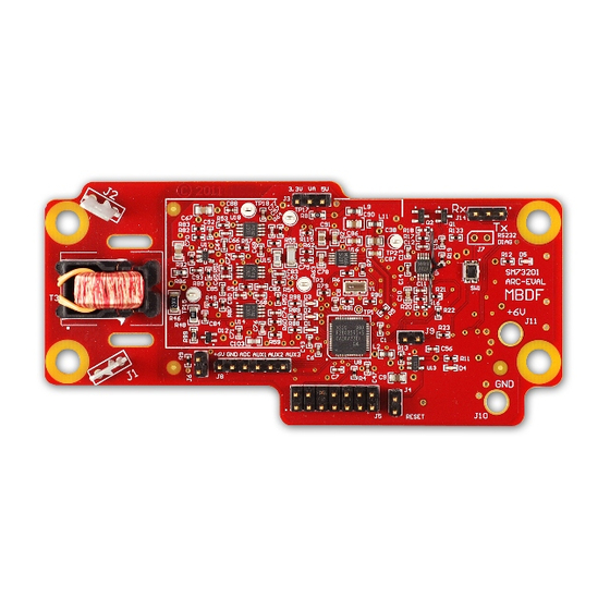
The RD-195 reference design includes the SM73201-ARC-EV PCB which is a UL1699B compliant Photo-
Voltaic Arc Detect System with a minimal footprint of less than 50mm x 30mm. The reference design
utilizes a proprietary dynamic filtering technique to effectively detect the signature of arcing conductors in
the presence of highly noisy real world environments. The analog path requires less than 50mW of power
to implement the active filtering. The operation range of the device covers the industrial temperature range
of -40°C to +85°C.
1
......................................................................................................................
2
...................................................................................................................
3
4
5
6
7
8
9
10
11
12
....................................................................................................................
13
14
15
.......................................................................................................................
16
17
18
19
20
21
22
.......................................................................................................................
23
24
1
2
3
4
5
6
7
8
9
SNOA564F - June 2011 - Revised December 2012
..................................................................................................................
....................................................................................................
............................................................................................................
................................................................................................
..............................................................................................................
..........................................................................................................
.....................................................................................
..........................................................................................................
........................................................................................................
....................................................................................................
..........................................................................................................
.............................................................................................
..........................................................................................
.........................................................................................
.....................................................................................................
................................................................................................................
...........................................................................................................
.............................................................................................................
............................................................................................................
............................................................................................................
............................................................................................................
...........................................................................................................
...........................................................................................................
...........................................................................................................
............................................................................................................
..............................................................................................................
Copyright © 2011-2012, Texas Instruments Incorporated
SNOA564F - June 2011 - Revised December 2012
ABSTRACT
Contents
..................................................................
List of Figures
.............................................................................
AN-2154 RD-195 DC Arc Detection Evaluation Board
Application Report
3
3
3
4
4
4
4
5
5
6
6
7
7
8
10
11
11
14
15
16
20
20
21
22
3
7
7
8
8
9
9
10
10
1
Advertisement
Table of Contents

Subscribe to Our Youtube Channel
Related Manuals for Texas Instruments AN-2154


Summary of Contents for Texas Instruments AN-2154
-
Page 1: Table Of Contents
Application Report SNOA564F – June 2011 – Revised December 2012 AN-2154 RD-195 DC Arc Detection Evaluation Board ..............................ABSTRACT The RD-195 reference design includes the SM73201-ARC-EV PCB which is a UL1699B compliant Photo- Voltaic Arc Detect System with a minimal footprint of less than 50mm x 30mm. The reference design utilizes a proprietary dynamic filtering technique to effectively detect the signature of arcing conductors in the presence of highly noisy real world environments. - Page 2 Project Source File Description .................... Miscellanous File Description ..................Linker Command File Description ..................Benchmark for the various routines AN-2154 RD-195 DC Arc Detection Evaluation Board SNOA564F – June 2011 – Revised December 2012 Submit Documentation Feedback Copyright © 2011–2012, Texas Instruments Incorporated...
-
Page 3: Introduction
The multiple connections on the Evaluation Board are labeled. Refer to the table below for a description of their usage. SNOA564F – June 2011 – Revised December 2012 AN-2154 RD-195 DC Arc Detection Evaluation Board Submit Documentation Feedback Copyright © 2011–2012, Texas Instruments Incorporated... -
Page 4: Quick Setup Procedure
When connected and powered up, the Evaluation Board will send out a version information header, then will transmit either “Arc Searching” or “Arc Detected” on the console port. AN-2154 RD-195 DC Arc Detection Evaluation Board SNOA564F – June 2011 – Revised December 2012 Submit Documentation Feedback Copyright ©... -
Page 5: Rs232 Commands
Note when arc detection is disabled, the Green LED will turn off and the Yellow LED will rapidly blink. SNOA564F – June 2011 – Revised December 2012 AN-2154 RD-195 DC Arc Detection Evaluation Board Submit Documentation Feedback Copyright © 2011–2012, Texas Instruments Incorporated... -
Page 6: Raw Data Capture
A reasonably sized transformer meeting these requirements has relatively low magnetization inductance. Because of this, the noise signal at the secondary of the transformer is relatively low. AN-2154 RD-195 DC Arc Detection Evaluation Board SNOA564F – June 2011 – Revised December 2012 Submit Documentation Feedback... -
Page 7: System Implementation
Arrays containing multiple PV strings can be serviced by connecting one arc detection board per string. SNOA564F – June 2011 – Revised December 2012 AN-2154 RD-195 DC Arc Detection Evaluation Board Submit Documentation Feedback Copyright © 2011–2012, Texas Instruments Incorporated... -
Page 8: Design Description
Install J9 jumper to generate a continuous noise signal. +V should be between 8 and 12 volts for proper operation of the noise circuit. AN-2154 RD-195 DC Arc Detection Evaluation Board SNOA564F – June 2011 – Revised December 2012 Submit Documentation Feedback Copyright ©... -
Page 9: Analog Front End
ADC_INPUT U15B VREF U18B U14B Figure 6. Analog Front End VREF TP18 Figure 7. Reference voltage SNOA564F – June 2011 – Revised December 2012 AN-2154 RD-195 DC Arc Detection Evaluation Board Submit Documentation Feedback Copyright © 2011–2012, Texas Instruments Incorporated... -
Page 10: Differentiation Of Series And Parallel Arcing Events
These are caused by any type of incomplete connection; examples include cold solder joints, conductor corrosion, and improperly mated connectors. AN-2154 RD-195 DC Arc Detection Evaluation Board SNOA564F – June 2011 – Revised December 2012 Submit Documentation Feedback... -
Page 11: Safety
Incandescent metal sparks and open flame can be present. Use all necessary safety gear, including Eye/Face protection, electrical gloves rated for the electrical conditions, and any other equipment appropriate for the conditions. Texas Instruments assumes no liability for any damage or injury that may occur. -
Page 12: Basic Setup Photo
Notice the long handle. Be sure to use a non-conductive material for the handle which is flame-resistant. Figure 13. Basic Setup Schematic AN-2154 RD-195 DC Arc Detection Evaluation Board SNOA564F – June 2011 – Revised December 2012 Submit Documentation Feedback... -
Page 13: Arc Generation Unit
Arc Generation unit producing an arc. This arc was generated with the DC power supply set to 130V, with a maximum current of 2.0A. SNOA564F – June 2011 – Revised December 2012 AN-2154 RD-195 DC Arc Detection Evaluation Board Submit Documentation Feedback Copyright © 2011–2012, Texas Instruments Incorporated... -
Page 14: Arc Detection Library Structure
Documentation for the current revision of the library including revision history <base>/include All device and library header files AN-2154 RD-195 DC Arc Detection Evaluation Board SNOA564F – June 2011 – Revised December 2012 Submit Documentation Feedback Copyright © 2011–2012, Texas Instruments Incorporated... -
Page 15: Using The Arc Detection Library
2. Add the name of the libraries(Arc Detection and Fixed Point) and their locations to the File Search Path as shown in Figure SNOA564F – June 2011 – Revised December 2012 AN-2154 RD-195 DC Arc Detection Evaluation Board Submit Documentation Feedback Copyright © 2011–2012, Texas Instruments Incorporated... -
Page 16: Structure Of The Code
Table Table 3, and Table 4 AN-2154 RD-195 DC Arc Detection Evaluation Board SNOA564F – June 2011 – Revised December 2012 Submit Documentation Feedback Copyright © 2011–2012, Texas Instruments Incorporated... -
Page 17: Project View In Ccs
Flash EEPROM Emulation Routines Arc_Detection-Main.c Main body of the code Arc_Detection-sciCOMM.c SCI-A Function Definitions Arc_Detection-spiADC_ASM.asm SPI-A bit-banging routine SNOA564F – June 2011 – Revised December 2012 AN-2154 RD-195 DC Arc Detection Evaluation Board Submit Documentation Feedback Copyright © 2011–2012, Texas Instruments Incorporated... -
Page 18: Build Configurations
Flash linker command file for F28035 SetupDebugEnv.js Script to setup the watch window and graphs in the debug perspective of CCS AN-2154 RD-195 DC Arc Detection Evaluation Board SNOA564F – June 2011 – Revised December 2012 Submit Documentation Feedback Copyright © 2011–2012, Texas Instruments Incorporated... -
Page 19: Flash Linker Command File
The test vectors are allocated to this section RawAdcBuffer The raw ADC capture buffer is allocated to this section SNOA564F – June 2011 – Revised December 2012 AN-2154 RD-195 DC Arc Detection Evaluation Board Submit Documentation Feedback Copyright © 2011–2012, Texas Instruments Incorporated... -
Page 20: Benchmarks
And don’t forget the TI community website: http://e2e.ti.com Building the Arc Detection library requires Codegen Tools v6.0.1 or later AN-2154 RD-195 DC Arc Detection Evaluation Board SNOA564F – June 2011 – Revised December 2012 Submit Documentation Feedback Copyright © 2011–2012, Texas Instruments Incorporated... -
Page 21: Layout
Layout www.ti.com Layout Figure 23. Board Assembly TOP SNOA564F – June 2011 – Revised December 2012 AN-2154 RD-195 DC Arc Detection Evaluation Board Submit Documentation Feedback Copyright © 2011–2012, Texas Instruments Incorporated... -
Page 22: Bill Of Materials
C60, C61, C68, C69, C71, C72, C77, C80, C88 CAP CER .10UF 16V X7R AUTO 0402 CGA2B1X7R1C104K AN-2154 RD-195 DC Arc Detection Evaluation Board SNOA564F – June 2011 – Revised December 2012 Submit Documentation Feedback Copyright © 2011–2012, Texas Instruments Incorporated... - Page 23 RES, 4.75k ohm, 1%, 0.063W, 0402 Vishay-Dale CRCW04024K75FKED R52, R54 RES, 5.11k ohm, 1%, 0.063W, 0402 Vishay-Dale CRCW04025K11FKED SNOA564F – June 2011 – Revised December 2012 AN-2154 RD-195 DC Arc Detection Evaluation Board Submit Documentation Feedback Copyright © 2011–2012, Texas Instruments Incorporated...
- Page 24 U14, U15, U18 SM73307MM IC ADC 16BIT 50/250KSPS 10-MSOP SM73201IMM CER RESONATOR 6.00MHZ SMD Murata CSTCR6M00G53–R0 AN-2154 RD-195 DC Arc Detection Evaluation Board SNOA564F – June 2011 – Revised December 2012 Submit Documentation Feedback Copyright © 2011–2012, Texas Instruments Incorporated...
- Page 25 STANDARD TERMS AND CONDITIONS FOR EVALUATION MODULES Delivery: TI delivers TI evaluation boards, kits, or modules, including any accompanying demonstration software, components, or documentation (collectively, an “EVM” or “EVMs”) to the User (“User”) in accordance with the terms and conditions set forth herein. Acceptance of the EVM is expressly subject to the following terms and conditions.
- Page 26 FCC Interference Statement for Class B EVM devices NOTE: This equipment has been tested and found to comply with the limits for a Class B digital device, pursuant to part 15 of the FCC Rules. These limits are designed to provide reasonable protection against harmful interference in a residential installation.
- Page 27 【無線電波を送信する製品の開発キットをお使いになる際の注意事項】 開発キットの中には技術基準適合証明を受けて いないものがあります。 技術適合証明を受けていないもののご使用に際しては、電波法遵守のため、以下のいずれかの 措置を取っていただく必要がありますのでご注意ください。 1. 電波法施行規則第6条第1項第1号に基づく平成18年3月28日総務省告示第173号で定められた電波暗室等の試験設備でご使用 いただく。 2. 実験局の免許を取得後ご使用いただく。 3. 技術基準適合証明を取得後ご使用いただく。 なお、本製品は、上記の「ご使用にあたっての注意」を譲渡先、移転先に通知しない限り、譲渡、移転できないものとします。 上記を遵守頂けない場合は、電波法の罰則が適用される可能性があることをご留意ください。 日本テキサス・イ ンスツルメンツ株式会社 東京都新宿区西新宿6丁目24番1号 西新宿三井ビル 3.3.3 Notice for EVMs for Power Line Communication: Please see http://www.tij.co.jp/lsds/ti_ja/general/eStore/notice_02.page 電力線搬送波通信についての開発キットをお使いになる際の注意事項については、次のところをご覧くださ い。http://www.tij.co.jp/lsds/ti_ja/general/eStore/notice_02.page SPACER EVM Use Restrictions and Warnings: 4.1 EVMS ARE NOT FOR USE IN FUNCTIONAL SAFETY AND/OR SAFETY CRITICAL EVALUATIONS, INCLUDING BUT NOT LIMITED TO EVALUATIONS OF LIFE SUPPORT APPLICATIONS.
- Page 28 Notwithstanding the foregoing, any judgment may be enforced in any United States or foreign court, and TI may seek injunctive relief in any United States or foreign court. Mailing Address: Texas Instruments, Post Office Box 655303, Dallas, Texas 75265 Copyright © 2015, Texas Instruments Incorporated...
- Page 29 IMPORTANT NOTICE Texas Instruments Incorporated and its subsidiaries (TI) reserve the right to make corrections, enhancements, improvements and other changes to its semiconductor products and services per JESD46, latest issue, and to discontinue any product or service per JESD48, latest issue.
- Page 30 Mouser Electronics Authorized Distributor Click to View Pricing, Inventory, Delivery & Lifecycle Information: Texas Instruments SM73201-ARC-EV/NOPB...
Need help?
Do you have a question about the AN-2154 and is the answer not in the manual?
Questions and answers