Table of Contents
Advertisement
Quick Links
This manual describes the software installation, driver installation, the modules and peripherals of
RF430F5978EVM. Each description presents the module or peripheral in a general sense. Not all features
and functions of all modules or peripherals may be present on all devices. In addition, modules or
peripherals may differ in their exact implementation between device families, or may not be fully
implemented on an individual device or device family.
Pin functions, internal signal connections, and operational parameters differ from device to device. The
user should consult the device-specific data sheet for these details.
SLRU007 – July 2014
Submit Documentation Feedback
RF430F5978EVM User Guide
Copyright © 2014, Texas Instruments Incorporated
User's Guide
SLRU007 – July 2014
RF430F5978EVM User Guide
1
Advertisement
Table of Contents

Related Manuals for Texas Instruments RF430F5978EVM


Summary of Contents for Texas Instruments RF430F5978EVM
- Page 1 This manual describes the software installation, driver installation, the modules and peripherals of RF430F5978EVM. Each description presents the module or peripheral in a general sense. Not all features and functions of all modules or peripherals may be present on all devices. In addition, modules or peripherals may differ in their exact implementation between device families, or may not be fully implemented on an individual device or device family.
-
Page 2: Table Of Contents
UHF Configuration Settings ..............Configuration Software for UHF block ..............RF430F5978EVM Hardware Description ................. Programming Hardware Interface ............Professional Software Development Tools ......................Schematics RF430F5978EVM User Guide SLRU007 – July 2014 Submit Documentation Feedback Copyright © 2014, Texas Instruments Incorporated... -
Page 3: Overview
Overview To get started evaluating the RF430F5978 MCU, system developers can purchase the RF430F5978EVM bundle. This bundle helps users evaluate the key features of RF430F5978 MCU: 3D LF wake-up and trigger function, passive battery-less transponder operation, and resonant trimming. -
Page 4: Rf430F5978 Demo Kit Overview
In a typical sequence, the MRD2EVM LF transmitter sends a 64-bit wake pattern and, as soon as the RF430F5978EVM board is within the supply range (typically 2 m with the components in this kit but can reach up to 10 m with an LF power transmitter) and detects a valid wake pattern, then activates the microcontroller. - Page 5 LF ANT Trimming LF Antenna Trimming function Test Hardware Function test AES Transponder AES Transponder function User Terminal About Software version and User Guide of RF430F5978EVM Tab 4 Tab 5 Tab 3 Tab 2 Tab 1 Figure 3. RF430F5978EVM GUI SLRU007 –...
-
Page 6: Kit Contents
RF430F5978EVM quick start guide • 1.27 4-pin connector Figure 4. RF430F5978EVM Package For complete ordering information, see the TI web site at www.ti.com/tool/RF430F5978EVM. Required Equipment The following equipment is required to operate the RF430F5978EVM: • A PC running the Windows 7 operating system •... -
Page 7: Set Up Rf430F5978Evm Demo
Set Up RF430F5978EVM Demo The following steps set up the hardware and sofware to run the default demo: 1. Insert the CR2032 battery in the RF430F5978EVM module as shown in Figure Figure 5. RF430F5978EVM Battery Assembly 2. Connect MRD2 reader and the AP434R01 access point to USB interfaces on the PC (see Figure Figure 6. - Page 8 C:\Program Files (x86)\RF430F5978EVM\Driver. Driver INF file: RF_AP.inf Follow the instructions of the operating system to install the driver. 5. Set the power switch on the RF430F5978EVM module to the battery mode (left position) (see Figure External VCC (SBW) Battery Mode...
-
Page 9: Start The Software
Start the Software www.ti.com Start the Software To run the software, click Start → All Programs → RF430F5978EVM → RF430F5978EVM. The LF reader and UHF access point will be automatically detected. 1. Start the software RF430F5978EVM. 2. Click "Connect". 3. Check if the Microreader and USB access point are available (see... - Page 10 5. Check if the Microreader and USB access point are available (see Figure Access point and MRD2 is now available Figure 9. RF430F5978EVM GUI Hardware Status 2 6. If both are available, the software is ready to start the demo. RF430F5978EVM User Guide SLRU007 –...
-
Page 11: Using The Lf Wake-Up Mode With Uhf Response
Using the LF Wake-Up Mode With UHF Response The following steps show how to enable complete (bidirectional) LF communication, which means that the MRD2 can send an LF wake pattern and can then receive the UHF response of the RF430F5978EVM module that receives the wake-up signal (see Figure 10). -
Page 12: Lf Wake-Up Mode Tab
USB Interface status Figure 11. RF430F5978EVM Wakeup Mode Demo 2 1. LF RSSI bars displays the different RSSI (received signal strength indicator) values of the 3D antenna (red for x, green for y, blue for z). The max value is 255 dBm. The RSSI value of each RF430F5978 antenna axis depends on the RF430F5978 module position and orientation relative to the LF trigger (MRD2). - Page 13 – Virtual com port, firmware version – Not found: No Micro Reader 2 available 5. Temperature and VCC graphical display • The red line represents RF430F5978EVM VCC module voltage. • The green line represents RF430F5978EVM module temperature. Continuous mode displays the last 50 packets.
-
Page 14: Lf Antenna Trimming Tab
LF Antenna Trimming Tab Figure 12 shows the LF Antenna Trimming Tab. Refer to the following description for more details. Figure 12. RF430F5978EVM LF Antenna Trimming Tab 1. Antenna RFx (x)-Axis • Get RSSI: Measure LF-RSSI of separate 3D Antennas •... -
Page 15: Test Tab
Red indicates that no MRD2 module is available. Check the USB connection. RF430F5978EVM Hardware test "RF430F5978EVM" Status Display: Green indicates that RF430F5978EVM LF and UHF communication are OK. The module name, serial number, and firmware version are reported. Red indicates that communication with the RF430F5978EVM module is not possible. Possible errors:... -
Page 16: Aes Transponder User Interface
Figure 14. RF430F5978EVM AES Transponder Tab 1 1. Transponder Bank 3/7 and Pages: Read Banks: Read out complete Bank 3 and Bank 7 Pages from RF430F5978EVM module Read Selected Page: Read out the selected page from RF430F5978EVM module Cancel reading: Cancel the read operation 2. - Page 17 AES Transponder User Interface www.ti.com Figure 15. RF430F5978EVM AES Transponder Tab 2 1. MRD2 Command: User input interface for setup direct hex commands Example: Set default timing "BLC (Automotive) Timing (Command 0x0D)" 01 12 83 0D 00 AA 01 CC 00 AA 00 E6 00 AA 01 5E 00 AA 02 44 AE...
- Page 18 For detailed information, see the RF430F59xx Family User's Guide (SLAU378) in the section "Low- Frequency Wake-Up Receiver". Wakeup and wait for AP command: "Send wakeup pattern A and setup the RF430F5978EVM module at UHF interface to Receive Mode" 01 08 C8 A0 00 00 01 08 88 0D EC The RF430F5978EVM module is waiting for commands from the UHF Access point Now the user has the possibility to communicate with own UHF –...
-
Page 19: Uhf Configuration Settings
TX power -20 dBm RF430F5978EVM power condition meets the FCC 5.231 requirements Configuration Software for UHF block The RF430F5978 can be configured by using the SmartRF™ Studio software (SWRC046). Because RF430F5978 selection is not available, CC430 and CC1101 settings must be selected in SmartRF Studio. -
Page 20: Rf430F5978Evm Hardware Description
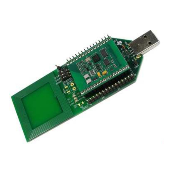
RF430F5978EVM Hardware Description www.ti.com RF430F5978EVM Hardware Description Figure 16. RF430F5978EVM Module RF430F5978EVM User Guide SLRU007 – July 2014 Submit Documentation Feedback Copyright © 2014, Texas Instruments Incorporated... -
Page 21: Programming Hardware Interface
Programming Hardware Interface www.ti.com Programming Hardware Interface 18.1 Required Adapter for Programming Interface The kit includes a JTAG/SBW adapter and a 4-pin connector for firmware change of the RF430F5978EVM module or AP434R01 module. Figure 17. JTAG/SBW Adapter Schematic Figure 18. 4-Pin Connector 18.2 Required Equipment to Program the RF430F5978EVM and AP434R01 Modules... - Page 22 1. Connect JTAG cable to MSP430 FET UIF or MSP-FET Tool and JTAG/SBW adapter. 2. Connect the 4-pin connector to JTAG/SBW adapter. 3. Connect the 4-pin connector to the RF430F5978 SBW pins on the RF430F5978EVM top layer and place the 4-pins in central position (see Figure 21).
-
Page 23: Professional Software Development Tools
Professional Software Development Tools Code Composer Studio™ IDE (CCSTUDIO) IAR Embedded Workbench (IAR-KICKSTART) For more information, see the TI web site at http://www.ti.com/lsds/ti/microcontrollers_16-bit_32- bit/msp/tools_software.page SLRU007 – July 2014 RF430F5978EVM User Guide Submit Documentation Feedback Copyright © 2014, Texas Instruments Incorporated... -
Page 24: Schematics
Schematics www.ti.com Schematics 20.1 RF430F5978EVM Figure 23. RF430F5978EVM Photo Figure 24. RF430F5978EVM Module Schematic 20.2 LF 3D Antenna Figure 25. LF 3D Antenna Schematic RF430F5978EVM User Guide SLRU007 – July 2014 Submit Documentation Feedback Copyright © 2014, Texas Instruments Incorporated... - Page 25 Schematics www.ti.com 20.3 APA434R01 Figure 26. APA434R01 Photo Figure 27. AP434R01 Module Schematic SLRU007 – July 2014 RF430F5978EVM User Guide Submit Documentation Feedback Copyright © 2014, Texas Instruments Incorporated...
- Page 26 Figure 28. MRD2EVM Photo Figure 29. MRD 2 Schematic For additional documents, such as the Microreader Evaluation Kit description and user guide, go to http://www.ti.com/tool/mrd2evm. RF430F5978EVM User Guide SLRU007 – July 2014 Submit Documentation Feedback Copyright © 2014, Texas Instruments Incorporated...
- Page 27 STANDARD TERMS AND CONDITIONS FOR EVALUATION MODULES Delivery: TI delivers TI evaluation boards, kits, or modules, including any accompanying demonstration software, components, or documentation (collectively, an “EVM” or “EVMs”) to the User (“User”) in accordance with the terms and conditions set forth herein. Acceptance of the EVM is expressly subject to the following terms and conditions.
- Page 28 FCC Interference Statement for Class B EVM devices NOTE: This equipment has been tested and found to comply with the limits for a Class B digital device, pursuant to part 15 of the FCC Rules. These limits are designed to provide reasonable protection against harmful interference in a residential installation.
- Page 29 【無線電波を送信する製品の開発キットをお使いになる際の注意事項】 開発キットの中には技術基準適合証明を受けて いないものがあります。 技術適合証明を受けていないもののご使用に際しては、電波法遵守のため、以下のいずれかの 措置を取っていただく必要がありますのでご注意ください。 1. 電波法施行規則第6条第1項第1号に基づく平成18年3月28日総務省告示第173号で定められた電波暗室等の試験設備でご使用 いただく。 2. 実験局の免許を取得後ご使用いただく。 3. 技術基準適合証明を取得後ご使用いただく。 なお、本製品は、上記の「ご使用にあたっての注意」を譲渡先、移転先に通知しない限り、譲渡、移転できないものとします。 上記を遵守頂けない場合は、電波法の罰則が適用される可能性があることをご留意ください。 日本テキサス・イ ンスツルメンツ株式会社 東京都新宿区西新宿6丁目24番1号 西新宿三井ビル 3.3.3 Notice for EVMs for Power Line Communication: Please see http://www.tij.co.jp/lsds/ti_ja/general/eStore/notice_02.page 電力線搬送波通信についての開発キットをお使いになる際の注意事項については、次のところをご覧くださ い。http://www.tij.co.jp/lsds/ti_ja/general/eStore/notice_02.page SPACER EVM Use Restrictions and Warnings: 4.1 EVMS ARE NOT FOR USE IN FUNCTIONAL SAFETY AND/OR SAFETY CRITICAL EVALUATIONS, INCLUDING BUT NOT LIMITED TO EVALUATIONS OF LIFE SUPPORT APPLICATIONS.
- Page 30 Notwithstanding the foregoing, any judgment may be enforced in any United States or foreign court, and TI may seek injunctive relief in any United States or foreign court. Mailing Address: Texas Instruments, Post Office Box 655303, Dallas, Texas 75265 Copyright © 2015, Texas Instruments Incorporated...
- Page 31 IMPORTANT NOTICE Texas Instruments Incorporated and its subsidiaries (TI) reserve the right to make corrections, enhancements, improvements and other changes to its semiconductor products and services per JESD46, latest issue, and to discontinue any product or service per JESD48, latest issue.
Need help?
Do you have a question about the RF430F5978EVM and is the answer not in the manual?
Questions and answers