Sign In
Upload
Manuals
Brands
LEMKEN Manuals
Farm Equipment
Albatros 9/4000
LEMKEN Albatros 9/4000 Manuals
Manuals and User Guides for LEMKEN Albatros 9/4000. We have
1
LEMKEN Albatros 9/4000 manual available for free PDF download: Operating Instructions Manual
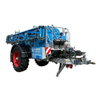
LEMKEN Albatros 9/4000 Operating Instructions Manual (318 pages)
Field Sprayer
Brand:
LEMKEN
| Category:
Farm Equipment
| Size: 7.96 MB
Table of Contents
Table of Contents
5
Contents
5
General Information
18
Liability
18
Guarantee
18
Copyright
19
Optional Accessories
19
Identification Plate
20
Implement
20
Axle
22
Automatic, Load-Dependent Brake Valve (ALB)
22
Symbols Used in the Operating Instructions
23
Hazard Classes
23
Information
23
Environmental Protection
23
Indication of Passages
24
Safety Measures and Precautions
25
Target Group
25
Intended Use
25
Safety and Warning Signs
27
General Information
27
Meaning of Warning Signs
27
Special Safety Instructions
29
Danger Areas
30
Danger Areas When Operating the Implement
31
Danger Area When Folding in and out
31
Residual Risks
32
Hazard Caused by Mechanical Systems
32
Dangers from the Oil Hydraulic System
32
Applicable Rules and Regulations
33
Operation on Public Highways
33
Lighting System and Identification
33
Permissible Weight of the Implement
33
Checks before Driving off
34
Requirements of the Tractor
35
Correct Behaviour in Road Traffic
35
Obligation of the Operator
36
Centring of the Steering Drawbar in the Middle Setting
37
Manual Drawbar Steering
37
TRAIL Control
38
Safe Operation of the Implement
39
General
39
Selection and Qualification of Personnel
39
Effect of Particular Agricultural Chemicals on the Implement
40
Handover of the Implement
41
Design and Function
42
Overview
42
Chassis, General
43
Drawbar with End Section and Drawbar Eye
43
Rigid Drawbar
43
Drawbar - Manual Steerable
43
Drawbar - Automatically Steerable (TRAIL Control)
44
Axles
44
Brake System
45
Without Brake System
45
Manually Regulated Air Brake System
46
Air Brake System with an Automatic, Load-Dependent Compressed Air Brake Valve and Pneumatic Suspension
49
Hydraulic Braking System
50
Fluid Circuit
51
Albatros 9/2000
51
Albatros 9/3000
52
Albatros 9/4000-5000-6000
53
Description
54
Flow of Liquid to the Nozzles
54
Main Tank
56
Fresh Water Tank
57
Hand Washing Container
57
Filter
58
Pump
59
Cardan Shaft
59
Hydraulic Drive
60
Control and Connection Centre
61
Selector Valve
61
Agitator Pump Valve
62
Distribution Valve
62
Agitator Control
63
Flushing Valve
63
Fresh Water Tank Valve
63
Induction Hopper
64
Induction Hopper Valve
65
Suction Valve
66
Connections
66
Pressure Limiting Valve
67
Hand Washing Container Drain Valve
67
Filler Valve
67
TANK Control Filling Level Indicator
68
Automatic Filling Stop
68
Filler Hose
69
Storage Compartment
69
Distance Detection
70
Flow Meter
71
Pressure Measuring Device
71
Feeding
71
Electro-Hydraulic Control
72
Standard
72
Load Sensing
72
Control Terminals
73
Spraydos
74
SPRAY-Control S
77
UNI-Control S
77
COMFORT- Terminal
78
LEMKEN CCI-200 Terminal
78
Multifunction Handle
79
Automatic Drawbar Control TRAIL Control
79
Spraying
80
Boom
81
S-Box
82
Height Adjustment
83
Swing Suspension and Slope Compensator
83
Electrical - Non-ISOBUS Control Terminal
83
Electrical or Electro-Hydraulic - Non-ISOBUS Control Terminal
84
Electrical or Electro-Hydraulic - ISOBUS Control Terminal
84
Stabiliser
84
DISTANCE Control
85
Hydraulic Flow Dividers and Pressure Limiting Valves
86
Segment Valves
86
Boom
87
Ground Distance Controllers
87
Nozzle Holder
87
Single Nozzle Holder
88
Three-Nozzle Holder
88
Four-Nozzle Holder
89
Vario Select Nozzle Holder
89
Nozzles
91
General
91
Liquid Fertilizer Nozzles
91
Drag Hose
92
Drag Pipe
92
Boundary Nozzles
93
Manual
93
Electrical
93
Edge Nozzles
93
Boom Lighting
94
Foam Marking
94
Preparations on the Tractor
95
Overview
95
Check Tractor Tire Pressure
95
Provide and Check the Necessary Electronics Connections
95
Provide and Check the Necessary Hydraulic Connections
97
Installation of the Control Terminal
98
Determining the Driving Speed
99
Installing the TRAIL Control Operating Terminal and the Angle Sensor
100
Mounting the Hydraulic Pump Drive Display and the Hydraulic Line
101
Preparation of the Device
102
Overview
102
Attaching the Implement
103
Calibrating the TRAIL Control Oil Quantity
110
Spraydos, SPRAY-Control S and UNI-Control S Operating Terminals
111
Mounting and Testing the Drive Shaft
112
Shortening the Drive Shaft
113
Determining the Filling Capacity of the Implement
114
Installation of the Correct Nozzles
117
Measuring Litres
119
General
119
For Spraydos Operating Terminals
120
Calibrating the Speed Sensor
121
General
121
For Spraydos Operating Terminals
122
With Other Operating Terminals
122
Calibrating the Flow Meter
123
General
123
For Spraydos Operating Terminals
123
Mounting the Drag Hoses
128
Preparation
128
Attaching
128
Mounting the Drag Pipes
131
Preparation
131
Attaching
131
Operation
133
Draining the Antifreeze
133
General
133
Brake System
133
Operation below Freezing Point
134
Storage Compartment
134
Operation Terminal
135
General
135
Spraydos
136
Other Operating Terminals
136
Filling and Emptying the Hand Washing Container
137
Filling the Hand Washing Container
137
Emptying the Hand Washing Container
138
Filling and Emptying the Fresh Water Tank
139
Filling the Fresh Water Tank
139
Emptying the Fresh Water Tank
140
Filling the Main Tank with Water
141
Cap of the Main Tank
142
Filler Valve Connection
143
Selector Valve Connection
145
Adjusting the Flushing Valve
148
Filling the Main Tank with Spraying Agent
150
Cap of the Main Tank
152
Filler Valve Connection
153
Selector Valve Connection
155
Filling Via the Induction Hopper
157
Shelf
158
Cleaning Empty Canisters
162
Cleaning Gun on the Induction Hopper
164
Flushing the Induction System
166
Folding out the Boom
168
With the Tractor Control Units
169
With Electro-Hydraulics and the Spraydos Operating Terminal
169
With Electro-Hydraulics and a Different Operating Terminal
170
Adjusting the Spring Stabiliser
171
Trial Operation of the Implement
172
Working with the Implement
174
Working on Uneven Ground or Slopes
177
Electrically with Button (Not ISOBUS Operating Terminal)
177
Electrically and Electro-Hydraulically with Potentiometer (Not ISOBUS Terminal)
177
Electrical or Electro-Hydraulic with Switch - ISOBUS Control Terminal
177
Working Headlights
178
Foam Marking
179
General
179
Commissioning
180
Notes
180
Boundary Nozzles
181
Manually Switched Boundary Nozzles
182
Electrically Switched Boundary Nozzles
183
Manually Switched Edge Nozzles
185
Electrically Activated Edge Nozzles Switched with Spraydos
186
Folding in the Boom
187
With the Tractor Control Units
188
With Electro-Hydraulics and the Spraydos Operating Terminal
189
With Electro-Hydraulics and a Different Operating Terminal
191
System Cleaning with Partially Filled Main Tank Using the Spraydos Operating Terminal
192
Spraying with Drag Hoses and Drag Pipes
195
Cleaning
196
General
196
Emptying the Main Tank
197
General
197
Pumping Residual Quantities from the Main Tank
198
Draining Spraying Agent out of the Main Tank
200
Emptying the Fresh Water Tank
201
Draining
201
Pumping out
202
Spraying
204
Internal Cleaning
205
General
205
Spraydos
205
Other Operating Terminals
206
External Cleaning
207
Cleaning the Filter
211
General
211
Suction Filter
212
Pressure Filter
213
Detaching the Implement
214
Winter Storage
219
Before the Start of the Season
220
Maintenance and Repairs
221
Special Safety Instructions
221
General
221
Personnel Qualifications
221
Protective Equipment
221
Immobilise the Implement for Maintenance and Repairs
222
Work on the Hydraulics
222
Working on the Electrics
223
Working under the Raised Device
223
Utilised Tool
223
Environmental Protection
224
Greasing
224
Maintenance Intervals
226
Oils and Lubricants
228
Hand Pump
228
Drive Shaft
229
Protective Tube
229
Safety Chain
229
Sliding Tube
229
Joints
229
Drawbar and Towing Equipment
230
Drawbar Eye
230
Stand
231
Drawbar Bearings
231
Steering Cylinder
231
Axle
232
Linkage Plate
232
Camshaft
232
Ladder
232
Gear Unit
233
Oil Change
233
Connection Sleeve
234
Lifting Mast
235
Lifting Mast and Floating Bearing
235
Slide and Swing Guide
235
Cable Roller
236
Cable
236
Boom
237
General
237
Vibration Damper
237
Folding Joint (1)
238
Folding Joint (2)
238
Folding Cylinder
239
Swivel Joint
239
Chains
240
Folding Joint (3)
240
Hydraulic Lines
240
Hydraulic Hoses
240
Oil Filter of the Electro-Hydraulic Control Unit
241
Checking the Oil Filter
241
Replacing the Oil Filter
241
Air Brake
243
General
243
Bleeding
243
Cleaning
244
Adjustment Centre
246
Selector and Distributor Valve
246
Induction Hopper
246
Tightening Torques
247
General Information
247
Bolts and Nuts Made of Steel
247
Bolts and Nuts Made of V2A
248
Wheel Nuts
249
Checking Connections to the Tractor
250
Hydraulic Connections
250
Electronic Connections
250
Pump
251
General
251
Oil Level
251
Diaphragms
252
Pressure in the Pressure Reservoir
253
Calibrating the Sensors
255
Filter
255
Control Connections
256
General
256
Pump Output
256
Flow Meter
256
Pressure Measuring Device
257
Work to be Performed by a Qualified. Authorised Person
257
Axle
257
Brake System
257
Inspection of the Implement
258
Information in Case of Faults and Malfunctions
258
Technical Data
259
Dimensions
259
Weights
261
Empty Weight
261
Permissible Weight
261
Load Data Depending on the Permissible Wheels
262
Drawbar with End Section and Drawbar Eye
266
Axles
267
General
267
Explanation of the Terms Offset and Track Change
268
Wheel Rims
269
Track Width
270
Albatros 9/4000, 5000 and 6000
271
Albatros 9/2000 and 3000
272
Coupling and Chassis
272
Automatic Drawbar Control with TRAIL Control
272
Tyres
273
Use of Own Wheels or Wheels Which Are Not Listed in the List of Wheels
274
Drive Shaft
275
Pumps
276
Allocation
276
Data for each Pump
277
Spraying Fluid System
278
Oil Hydraulic System
279
Implement System
279
Hydraulic Pump Drive
279
Pressure Limiting Valves
279
Electronic Pressure Display
280
Filter
280
Tank Volume
281
Boom
282
Boom
283
Boom
284
Appendix
285
General Information about Nozzles
285
Nozzle Field of Application
286
Nozzle Tables
287
Nozzle Sizes 01 - 05
287
Nozzle Sizes 06 - 10
288
Correction Factors for Spraying Liquids with Different Densities
288
Edge Nozzles
289
Dosage Table for Liquid Fertilizer
290
Dosage Table for Drag Hoses with 25 CM Hose Spacing
290
Dosage Table for Liquid Fertilizer Nozzle SJ 7
292
Dosage Table for Five-Hole Nozzle FL
294
AHL (28/1.28 Kg/L) Dosage Table for ID-, IDN-, IDK-, IDKN- and FL Nozzles
295
Dosage Table for Liquid Fertilizer Nozzle FD
297
Dosage Table, Six-Hole Nozzle ESI
299
Assignment Plan of the Electro-Hydraulic Operation Unit; Positioning of the Hydraulic Valves
301
Test Connections
302
Pump Testing
302
Testing the Flow Meter
305
Testing the Pressure Measuring Device
306
Technical Residual Quantities
308
Matrices
309
Noise, Airborne Sound
316
Notes
316
Index
317
Advertisement
Advertisement
Related Products
LEMKEN Solitair 9
LEMKEN Solitair 9 KA
LEMKEN Karat 9U
LEMKEN Albatros 9/2000
LEMKEN Albatros 9/3000
LEMKEN Albatros 9/5000
LEMKEN Albatros 9/6000
LEMKEN 9 Z10
LEMKEN Compact-Solitair 9 HD
LEMKEN System-Korund 900
LEMKEN Categories
Farm Equipment
Tiller
Paint Sprayer
Control Systems
Controller
More LEMKEN Manuals
Login
Sign In
OR
Sign in with Facebook
Sign in with Google
Upload manual
Upload from disk
Upload from URL