Table of Contents
Advertisement
Quick Links
Advertisement
Table of Contents

Related Manuals for HAKO Sweepmaster P1500 RH


Summary of Contents for HAKO Sweepmaster P1500 RH
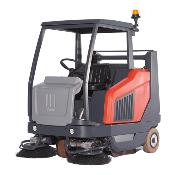
- Page 1 Instruction Manual Sweepmaster P1500 RH (6464.10) Sweepmaster D1500 RH (6464.30)
- Page 2 Any spect of the vehicle or operating manu- use beyond this is regarded as improp- al, your authorized Hako dealer is er use. The manufacturer is not consid- available to provide help at any time. ered liable for any damage resulting from improper use;...
-
Page 3: Notes On Warranty
Introduction Notes on warranty our authorized sales partner together Hako dealer in accordance with the Bat- with the consignment note. tery Law § 6 and § 8 (BattG). The terms defined in the purchase Disposing of the machine Regulations for approval agreement apply. - Page 4 Introduction cense, the license becomes invalid. To acquire a new vehicle registration li- cense, the vehicle must be presented to an officially accepted expert to produce a new report. The report becomes the official vehicle registration license when the vehicle registration office applies the applicable stamp.
-
Page 5: Table Of Contents
5.8.3 Change hydraulic oil filter. . . 62 Operating information..8 Hako System Maintenance . 45 Sweeping unit... . 63 Maintenance information . . . 10 Maintenance report . - Page 6 Table of Content 5.10.1 Checking tire wear ..71 5.10.2 Changing tires ... 71 5.10.3 Brakes ....71 5.11 Electronics .
-
Page 7: Safety Information
Safety Information Safety Information Safety and warning symbols All sections related to personal safety, safety of the vehicle and environmental protection are assigned the following symbols throughout the operating man- ual: Symbol Risks to ... Definition Safety information persons Safety information on preventing hazardous situations or property caused by failure to follow instructions or prescribed working procedures accurately or at all. -
Page 8: General Information
• The vehicle is not suitable for clear- • Persons being trained by qualified cerned, spare have to equal genuine ing up hazardous, inflammable or Hako technicians only are autho- spare parts! explosive fluids, dust or substances. rised to operate, service and repair •... - Page 9 Safety Information and rear path of travel and working when driving at higher speeds, tak- Only empty the sweepings container area! ing corners at too high a speed could on level, solid ground. • For safety reasons, the driver's seat cause the vehicle to tip.
-
Page 10: Maintenance Information
The use of other rotary brushes and pair one on a rim. Always go to a your nearest Hako service center. side brushes could impair safety. proper workshop for work on tires • The maintenance work and mainte- •... -
Page 11: Particular Risks
Electronics tect it from soiling by metallic dust, Hako or recognized brake service • Only use original fuses with the pre- for example. workshops. scribed amperage. -
Page 12: Environmental Protection
Safety Information connections and cable damage, agreed on with your authorized Hako must be rectified immediately. dealer in accordance with the Bat- • Observe the information in the oper- tery Law § 6 and § 8 (BattG). ating manual provided by the battery manufacturer. -
Page 13: Labels On The Vehicle
Fuses (Fig. 1/11) (Fig. 1/7) Vehicle identification number (Fig. 1/3) Sound power / Gradient (Fig. 1/8) Risk of crushing by sweepings 6464xxxxxxxx container (Fig. 1/12) Sweepmaster P1500 RH Sweepmaster D1500 RH Machine model (Fig. 1/4) Sweepmaster P1500 RH Sweepmaster D1500 RH... - Page 14 Safety Information Fig.1...
- Page 15 Safety Information Brush wear compensation Hot surface on exhaust manifold (Fig. 2/1) (Fig. 2/4) Risk of crushing in fan (Fig. 2/5) Keep clear of sweepings container (Fig. 2/2) Risk of crushing by sweepings container (Fig. 2/6) Hydraulic oil (Fig. 2/3)
- Page 16 Safety Information Fig.2...
-
Page 17: Operation
Instructions to operators are required before putting the machine into service. Only technicians from your local autho- rized Hako dealer are allowed to pro- vide initial instruction on the machine. The manufacturing plant will notify the dealer immediately after delivering the vehicle and the dealer will contact you to arrange a date. -
Page 18: Prior To Starting Up
Operation Prior to starting up Read the operating instruc- tions concerning the vehicle provided in Chapter 1, ob- served them and familiarize yourself with the operating pro- cedures. 1. Check the parking space for signs of leaks. Hoses, lines and tanks must show no signs of leaks or damage. -
Page 19: Starting The Engine
Operation Starting the engine has been switched off. A restart blocking system in the ignition lock Pay attention to the following prevents restarting when the engine information before starting the is running. vehicle: • Attempt to start continuously for max. 20 seconds, allow a short •... - Page 20 Operation Procedure to start the diesel engine (only for Sweepmaster D): 1. The accelerators (Fig. 4/1) must be in their neutral setting. 2. The vehicle's parking brake must be applied (Fig. 4/2). 3. Set the engine speed switch (Fig. 4/ 3) to working speed (hare).
- Page 21 Operation Procedure to start the petrol engine (only for Sweepmaster V): 1. The accelerators (Fig. 5/1) must be in their neutral setting. 2. The vehicle's parking brake must be applied (Fig. 5/2). 3. Actuate choke (with cold engine on- ly). 4.
-
Page 22: Stopping And Switching Off The Vehicle
Operation Stopping and switching off the vehicle 1. Move the accelerator (Fig. 6/1) slow- ly to its zero setting. The vehicle slows down to a stop. 2. Apply the parking brake (Fig. 6/2) to its end position and lock in place. 3. -
Page 23: Sweeping Operation
Operation Sweeping operation 1. Check the vehicle , refer to Section 2.2. 2. Start the vehicle, refer to Section 2.3. 3. Set the engine speed switch (Fig. 7/ 1) to working speed (Hare). 4. Switch on the sweeping function with the button (Fig. -
Page 24: Emptying The Sweepings Container
Operation 2.5.1 Emptying the sweepings container Observe the following safety information before emptying: • Driving the vehicle with the sweep- ings container raised reduces the ve- hicle's stability. Therefore, only raise the sweepings container immediate- ly prior to emptying it. •... - Page 25 Operation Procedure to empty the sweepings container: The sweepings container must be emp- tied at regular intervals. Ensure the maximum fill weight is never exceeded. 1. Switch off the sweeping functions with the button (Fig. 8/F). The filter agitating system is activated. 2.
-
Page 26: Function Faults
Clear the fault or note down the service The following applies when lo- In the case of system errors, a four-digit code and inform your authorized Hako cating and clearing faults: error code appears in the left-hand op- dealer. When the cause has been... - Page 27 Operation Error code Cause Solution 2.6.6.1. Turn hydraulic valve for sweepings container Check hydraulic valve Y7/Y6, ignition key OFF/ON and (overloaded, defective or not connected) restart engine 2.6.6.2. Hydraulic valve for sweepings container "Raise/ Check hydraulic valve Y9/Y8, ignition key OFF/ON and Lower"...
-
Page 28: Transporting
Operation Transporting In order to transport the vehicle on a loading space, apply the parking brake and also secure the vehicle using straps at both front lashing points (Fig. 9/1) and the two rear lashing points (Fig. 9/2) which are located in the wheel case. -
Page 29: Operation
Operation Operation Method of operation General information The Sweepmaster is a sweeping vehi- cle exclusively designed for sweeping up dry and wet waste from floor surfac- es as in production plants, warehouses, car parks and pedestrian precincts. Sweeping The side brush (Fig. 10/1) sweeps the dirt directly into the pick-up path (Fig. -
Page 30: Operating Elements
Operation Operating elements 3.2.1 Operating panel A 1 Control lamp for preheating 2 Control lamp for engine oil pressure 3 Control lamp for parking brake 4 Control lamp for service indicator 5 Operating hour counter / Service code 6 Control lamp for fuel reserves 7 Control lamp for coolant tempera- ture 8 Button to raise the sweepings con-... - Page 31 Clear the fault or note down the service (Fig. 11/6) the control lamp does not go out after code and inform your authorized Hako It lights up as soon as only approx. 3 li- refilling, contact your authorized Hako dealer. After clearing the fault, acknowl- ters of fuel remain in the tank.
- Page 32 Operation Control lamp for coolant tempera- Button to pivot the sweepings Button to lower the sweepings container for emptying (Fig. 11/9) container (Fig. 11/11) ture (Fig. 11/7) It serves to pivot the sweepings con- It serves to lower the sweepings con- It lights up as soon as the coolant has tainer to a vertical position for emptying.
- Page 33 Operation Button for suction turbine (Fig. 11/ Button for sweeping functions (Fig. 11/15) It serves to switch the sweeping opera- It serves to switch the suction turbine on tions on and off. The rotary brush, side and off. When the suction turbine is brush and suction turbine are switched switched on, the control lamp in the but- on and off.
-
Page 34: Operating Panel B
Operation 3.2.2 Operating panel B 1 Ignition starter switch 2 Load control lamp 3 Switch for engine speed 4 Horn switch 5 Switch for parking light/driving lights (option) 6 Switch for hazard lights (option) 7 Switch for flashing beacon (option) 8 Switch for drive direction indicator with control lamp (option) 9 Choke (Sweepmaster V only) - Page 35 Ignition starter switch (Fig. 12/1) Load control lamp (Fig. 12/2) Switch for horn (Fig. 12/4) It serves for preheating (Hako Jonas It lights up as soon as the ignition switch An acoustic signal is issued on actuat- 1500 D only), to switch the engine on/ is actuated and goes out when the en- ing the switch.
-
Page 36: Operating Elements On The Ma- Chine
Operation 3.2.3 Operating elements on the Service brake and parking brake Pedal for rotary brush pressure machine The service brake (Fig. 14/1) actuates The pedal (Fig. 15/1) serves to increase Accelerators the mechanical drum brakes which act the rotary brush pressure applied on the They serve for driving forward and in re- on the two rear wheels. - Page 37 Operation Pedal for front skirt Crank for setting the sweeping pattern Locking the seat console The pedal (Fig. 17/1) is used to raise The crank (Fig. 17/1) is used to set the For reasons of safety, the seat console the front skirt when sweeping large de- sweeping pattern of the rotary brush.
- Page 38 Operation Checking the sweepings container Filter system lock Dual Fuel System (Option) The sweepings container is provided The filter system is above the sweep- The vehicle is optionaly equipped with a with an opening in order to throw in ings container. The cover of the filter dual fuel system.
- Page 39 Operation Driver's seat The driver's seat (Fig. 22/1) must be ad- justed so that the driver is seated com- fortably and can reach all the operating elements with ease. • The seat suspension can be adapted to the driver's weight (50 kg to 120 kg) using the handwheel (A).
- Page 40 Operation Cab (optional) Swinging the cab up The cab can be swung up for mainte- nance work. Please follow the order described below, since otherwise the cab or machine may be damaged. 1. Switch the engine off and close the cab door.
- Page 41 Operation Lowering the cab 1. Switch the engine off and close the cab door. 2. Open the side flap and fit the pump lever onto the hand pump (Fig. 12/1). 3. Set the handle (Fig. 12/2) on the pump to "LOWER" (arrow down- wards) and pump the cab down with the pump lever until it moves no fur- ther.
- Page 42 Operation Cab heating (optional) Heating control knob The temperature is set with the controller (Fig. 13/1). Setting warmer: Turn the controller clockwise Setting colder: Turn the controller counter-clockwise Switch for heating blower The heating blower is switched on with the switch (Fig. 13/2). I = slow stage II = fast stage Adjusting the air vents...
-
Page 43: Technical Data
Technical Data Technical Data Dimensions and weight Length 2256 Width with/without left-hand side brush 1316/1363 Height with/without protective roof 1600/1985 Dead weight 1100 Permissible total weight 1900 Driving and sweeping performance Driving speed - forwards Driving speed - reverse Max. sweeping speed Theoretical sweeping performance with/without left-hand m²/h 16200/9300... - Page 44 Technical Data Sweepings container and filter system Sweepings container volume Liters Filter surface m² Side brushes Diameter Speed Max. 95 +/-5 Wheels Tyres, front 4.00-8 Tyres, rear Air/CSE 4.00-8 Hydraulic system Hydraulic oil, e.g. Mobiloil DTE 15M or DTE 10 Excel Tank volume Liters Electrical installation...
- Page 45 Technical Data Diesel engine (Sweepmaster D) Manufacturer Kubota Type Diesel D902 Working process / No. of cylinders 4 stroke / 3 Cubic capacity cm³ Output at 2700 rpm Idling speed 1500 +/-50 Working speed 2700 +/-50 Coolant Coolelf Auto Supra -37°C Coolant fill quantity Liters Approx.
- Page 46 Technical Data Gasoline/Petrol engine (Sweepmaster V) Manufacturer Kubota Type Gasoline/Petrol DF752 Working process / No. of cylinders 4 stroke / 3 Cubic capacity cm³ Output at 2700 rpm Idling speed 1500 +/-50 Working speed 2700 +/-50 Coolant Coolelf Auto Supra -37°C Coolant fill quantity Liters Approx.
- Page 47 Technical Data Sweepmaster D1500 RH Sweepmaster P1500 RH Noise emission values The sound pressure level (LpA) (at the ear of the operator) mea- sured according to DIN IEC 60335-2-72 under normal working conditions is: dB (A) Measurement inaccuracy (KpA): dB (A)
-
Page 48: Maintenance And Care
Please contact er/operator will be instructed upon de- Hako-System Maintenance IV/S: your local Hako Service Centre or Hako livery of the machine. (every 1000 hours of operation safety contract dealer. We cannot be held lia-... -
Page 49: Maintenance Report
Maintenance and Care Maintenance report Handover Hako System Maintenance Hako System Maintenance I Hako System Maintenance II 50 operating hours, one-off 125 operating hours 250 operating hours Upgrading Workshop Stamp Workshop Stamp Workshop Stamp Test drive Handover to customer Instruction... -
Page 50: Maintenance Plan
Maintenance and Care Maintenance plan Hako system maintenance, customer The following maintenance work must be completed by the customer at the in- tervals stipulated. Interval Activity Daily Check the fuel supply, refill as necessary Check the sweepings container, empty as necessary... - Page 51 Maintenance and Care Hako system maintenance, customer The following maintenance work must be completed by the customer at the in- tervals stipulated. Interval Activity Weekly Check the radiator cooling ribs, clean as necessary Check the function of the steering Check the the tire pressure...
- Page 52 Maintenance and Care Hako system maintenance - one-off The following maintenance work must be completed by an authorized Hako service center. Interval Activity Every 50 operating hours (one-off) Change the engine oil Change the engine oil filter Check the engine speed (idling and operating speed)
- Page 53 Maintenance and Care Hako system maintenance I The following maintenance work must be completed by an authorized Hako service center. Interval Activity Every 125 operating hours Check the exhaust system (risk of poisoning with cab option and defective exhaust sytem)
- Page 54 Interval Activity Every 250 operating hours All maintenance work in accordance with Hako system maintenance I Check the traction drive (forward and reverse drive, neutral position) Check the main filter of the air filter Change the engine oil...
- Page 55 The following maintenance work must be completed by an authorized Hako service center. Interval Activity Every 500 operating hours All maintenance work in accordance with Hako system maintenance I and II Change the hydraulic oil Change the hydraulic oil filter Change the fuel filter...
- Page 56 Interval Activity Every 1000 operating hours All maintenance work in accordance with Hako system maintenance I, II and III Change the air filter safety cartridges Change the coolant in the cooling system Change the brake shoes Change the brake Bowden cables...
-
Page 57: Seat Console
Maintenance and Care Seat console The engine, air filter, radiator, hydraulic system and other components are lo- cated under the seat console. The seat console can be pivoted up for cleaning and maintenance purposes. Allow the engine to cool down before starting any cleaning and maintenance work. -
Page 58: Engine
Maintenance and Care Engine The engine is installed under the seat console. Allow the engine to cool down before starting any cleaning and maintenance work. Other- wise you could burn yourself on hot surfaces! Pay attention to rotating parts in the vicinity of the fan. Risk of injury! 1 Dipstick 2 Cap... -
Page 59: Refilling The Engine Oil
Maintenance and Care 5.5.1 Refilling the engine oil 5.5.2 Changing the engine oil and 5.5.3 Changing the fuel filter Check the engine oil level with the oil oil filter Change the fuel filters (Fig. 23/6) and dipstick (Fig. 23/1) every day. Refill en- Change the engine oil and oil filter (Fig. -
Page 60: Air Filter
Maintenance and Care Air filter The air filter is located under the seat console. Allow the engine to cool down before starting any cleaning and maintenance work. Other- wise you could burn yourself on hot surfaces! Pay attention to rotating parts in the vicinity of the fan. -
Page 61: Cleaning The Dust Discharge Valve
Maintenance and Care 5.6.1 Cleaning the dust discharge signs of damage. The safety cartridge must be replaced valve every 1000 operating hours at the lat- 5.6.4 Installing the main filter The dust discharge valve (Fig. 25/1) est. 1. Slide the main filter (Fig. 25/5) back must be cleaned every day. -
Page 62: Cooling System
Maintenance and Care Cooling system The combined radiator (Fig. 26/1) cools both the cooling water for the engine as well as the hydraulic oil for the work hy- draulics. The coolant is cooled in the ra- diator by means of a fan (Fig. 26/2). If the coolant temperature is too high, it is indicated in the operating panel. -
Page 63: Cleaning The Radiator
Maintenance and Care 5.7.1 Cleaning the radiator 3. Replace the cap. 6. Allow the engine to run for a few min- Check the radiator (Fig. 26/1) daily and 4. Allow the engine to run for a few min- utes. clean as necessary. Dirt on the radiator utes. -
Page 64: Hydraulic System
Maintenance and Care Hydraulic system Work on the hydraulic system may only be carried out by technical experts and corre- spondingly trained personnel! Hydraulic oil under high pres- sure can cause severe injuries! Allow the engine to cool down before starting any cleaning and maintenance work. -
Page 65: Filling Hydraulic Oil
Maintenance and Care 5.8.1 Filling hydraulic oil Switch the engine off and apply the 5.8.3 Change hydraulic oil filter Check the oil level of the hydraulic oil parking brake. The hydraulic oil filter must be changed tank every day. 2. Place a suitable collecting vessel un- for the first time after 50 operating hours der the draining hose (Fig. -
Page 66: Sweeping Unit
Maintenance and Care Sweeping unit 1 Side brushes 2 Rotary brush 3 Sweepings container 4 Suction turbine 5 Filter system Fig.28... - Page 67 Maintenance and Care 5.9.1 Side brushes 1 Adjusting bolt 2 Side brushes 3 Catch Fig.29...
-
Page 68: Adjusting The Side Brushes
Maintenance and Care 5.9.2 Adjusting the side brushes Check the side brushes (Fig. 29/2) ev- ery week for signs of wear. In the event of wear or after the side brushes have been changed, proceed as follows to complete the necessary adjustments: 1. -
Page 69: Rotary Brush
Maintenance and Care 5.9.4 Rotary brush 1 Rotary brush 2 Sealing strip, left 3 Sealing strip, front 4 Sealing strip, rear 5 Sealing strip, right 6 Rotary brush half 7 Screw connection (5 pieces) 8 Crank brush wear 9 Scale Fig.30... -
Page 70: Setting The Sweeping Pattern
Hako service center. in the catches and to the direction of 1. Lower the rotary brush onto a the bristles. The alignment of the 5.9.7 Changing the rotary brush... -
Page 71: Adjusting The Sealing Strips
Maintenance and Care 5.9.8 Adjusting the sealing strips 5.9.9 Changing the sealing strips Check the sealing strips in the rotary Check the sealing strips in the rotary brush area every week, readjust as brush area weekly for signs of wear, re- necessary. -
Page 72: Filter System
Maintenance and Care 5.9.10 Filter system 1 Lock 2 Cover 3 Holder 4 Wing bolt 5 Frame 6 Agitating device 7 Dust filter Fig.31... -
Page 73: Cleaning The Dust Filter
Maintenance and Care 5.9.11 Cleaning the dust filter 5.9.12 Changing the dust filter The dust filter (Fig. 31/7) is located un- 1. Park the vehicle on a level area of der the cover (Fig. 31/2). The fine dust floor. Switch the engine off and apply swirled up by the rotary brush is drawn the parking brake. -
Page 74: Wheels And Brakes
Maintenance and Care 5.10 Wheels and brakes 5.10.2 Changing tires 5.10.3 Brakes Work on the wheels may only Work on the brake system may be carried out by technical ex- only be carried out by technical perts and correspondingly experts and correspondingly trained personnel! trained personnel! 1. -
Page 75: Electronics
Maintenance and Care 5.11 Electronics 5.11.1 Fuses The fuse box (Fig. 33/1) is on the right- hand side of the foot area. The main fuse and pre-fuse are located in the en- gine compartment in front of the battery. F1 Main fuse (50A) F2 Pre-fuse (50A) F3 Lighting (15A) (option) F4 Hazard warning light (10A) (option) -
Page 76: Relays
Maintenance and Care 5.11.2 Relays K1 Starter release relay, K2 Cab relay K3 Driving lights relay (option) K12 Indicator relay (option) 5.11.3 Changing the battery The negative pole of the bat- tery (Fig. 34/1) must be discon- nected from the battery before the positive pole. -
Page 77: Special Equipment And Replacement Demands
Maintenance and Care 5.12 Special equipment and replacement demands Name Description Order no. Liquefied petroleum gas system Attachment kit for liquefied petroleum gas without change bottle 6401 Dual Fuel System Attachment kit for switching between liquefied petroleum gas/pet- 640110 Cab safety roof Based on IEC 60335-2-72 CC 6474 Cab paneling... - Page 78 Maintenance and Care...
-
Page 79: Ec Declaration Of Conformity
D-23843 Bad Oldesloe plementation of the safety and health requirements in the EC Directive: Ludger Lüttel declares that the product DIN EN 60335-2-72 Sweepmaster P1500 RH DIN EN 61000-6-2 Typ: 6464.10 DIN EN 55012 Sweepmaster D1500 RH Typ: 6464.30 Bad Oldesloe, 22.04.2014... - Page 80 Spitzentechnik für eine saubere und schönere Umwelt Advanced Technology for a Cleaner, Better Environment · · Hako GmbH Hamburger Str. 209-239 D-23843 Bad Oldesloe · +49 4531 806-0 Fax +49 4531 806-338...
Need help?
Do you have a question about the Sweepmaster P1500 RH and is the answer not in the manual?
Questions and answers