
Related Manuals for HAKO Citymaster 1600


Summary of Contents for HAKO Citymaster 1600
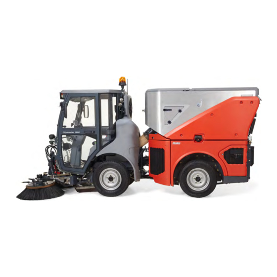
- Page 1 Cleaning technology Municipal technology • Citymaster 1600 (1491) Operating Manual Issue: 04.2016 Part number: 88-10-3036-3451-01...
-
Page 2: Introduction
We have provided the places in this operating manual concerning your safety with a danger pictogram. Your authorised Hako dealer is available at all times to answer further questions about the vehicle or the operating manual. -
Page 3: Applications
The Classic vehicle version is equipped with hot water heating. The Comfort vehicle version is equipped in addi- tion with an air conditioner. Your authorised Hako dealer is available to you at all times to answer questions on further applications. -
Page 4: Vehicle Data
Introduction Vehicle data Your vehicle is described clearly by the following data. Please always quote these data in correspondence or when making a telephone query to your authorised Hako dealer or our company. Vehicle type: • Chassis No.: • Engine No.: •... -
Page 5: Intended Use
Conditions for approval The Citymaster 1600 is a multi-purpose machine (tractor for use in agriculture or forestry) in terms of the EC Directive 2003/37/EC. The manufacturer provides an EC Certificate of Conformity and an EC Declaration of Con- formity. -
Page 6: Driving License
Introduction Driving license According to the driving license law in Germany the Citymaster 1600 may be driven as a multi-purpose machine (tractor) by drivers with the following classes of driving license: Class L (Class L is contained in Class B):... -
Page 7: Table Of Contents
Table of contents Introduction ...................... 2 Foreword ......................2 Applications ......................3 Vehicle data ....................... 4 Intended use ...................... 5 Notes on warranty ....................5 Acceptance of the vehicle .................. 5 Conditions for approval ..................5 Driving license ....................6 Equipment ...................... - Page 8 3.5.1 Transporting the vehicle .................. 79 3.5.2 Towing the vehicle ................... 80 Working with attachments ................81 3.6.1 Hako attachments ................... 81 3.6.2 Non-Hako attachments ..................81 3.6.3 Ballast ......................82 Technical Data ....................85 Maintenance and Servicing ................88 Maintenance certificate ...................
- Page 9 Table of contents 6.1.1 Labels on the unit .................... 119 6.1.2 Vacuum sweeping system safety instructions ..........119 6.1.3 Mounting ......................120 6.1.4 Operation ......................128 6.1.5 Technical data ....................146 6.1.6 Maintenance ....................149 6.1.7 Troubleshooting ....................158 6.1.8 Accessories .....................
-
Page 10: Safety Instructions
Safety Instructions 1 Safety Instructions Marking of warning and danger symbols Important tasks concerning the safety of the operator and vehicle are named as follows in this operating manual and emphasised by symbols. Danger Indication of a direct danger with high risk, in which death or severe physical injury can occur if it is not avoided. -
Page 11: General Safety Instructions
Before the vehicle is put into service, please read carefully the operating manual you receive as well as further • separate instructions for additional implements or attachments and observe them in all aspects in your work. The vehicle may be used, maintained and repaired only by persons who have been instructed by Hako • experts. -
Page 12: Safety Instructions For Attachments
• Always secure the front attachment with the locking devices. Risk of accident! You must consult Hako before attaching other attachments not approved by Hako! Check in • the individual case that the relevant axle loads and total weights are complied with. - Page 13 Risk of accident! Do not exceed the permissible total weight of the vehicle! • Risk of accident! When the dirt hopper is emptied, the Citymaster 1600 must be on a sufficiently load bearing, • horizontal surface. Driving with the dirt hopper tilted is not permitted.
- Page 14 Safety Instructions The lawn mowing system may be operated only in connection with the Citymaster 1600. The safety regula- • tions for the Citymaster 1600 must be complied with absolutely. Sweeping system Danger to life in the danger area of the vehicle! Special caution is required in the area of the articulated •...
-
Page 15: Information About Special Risks
Safety Instructions Information about special risks Exhaust gases Toxic engine exhaust gases! Inhaling exhaust gases is injurious to health and can lead to unconsciousness • and to death! Never let the engine run in enclosed spaces. Re-fuelling the vehicle Risk of fire! Diesel fuel is flammable! Take the utmost care when handling fuel. Never refuel close to naked •... - Page 16 Do not perform any welding, drilling, sawing or grinding work on parts of the frame. Damaged parts may be • replaced only by your authorised Hako dealer. After cleaning, examine all fuel, engine oil and hydraulic pipes for leaks, abrasion places and damage.
- Page 17 Use only original fuses. If stronger fuses are used, the electrical system can be destroyed and there can be • fires. Welding work on the vehicle may be done only by authorised Hako dealers. Welding work on the vehicle leads • to damage to the control electronics and can impair driving safety.
-
Page 18: Environmental Protection Instructions
Return and recycling have to be arranged with the authorised Hako dealer as required in § 6 and § 8 of the German battery law (BattG)! -
Page 19: Shutting Down And Disposal
The operating materials in the vehicle require special disposal and may not get into the environment. Further information about disposal is available through the competent local authorities and the authorised Hako dealer. Do not dispose of products with the symbol at the end of their life in the domestic waste. -
Page 20: Labels On The Vehicle
Safety Instructions Labels on the vehicle The following safety and instruction labels are affixed well legibly to the vehicle. Renew missing or illegible labels immediately. Citymaster 1600 Fig. 2: 01-1491-00-12.fm... - Page 21 Safety Instructions Hako company logo Fig. 2-A The Hako company logo (147 mm x 40 mm) is located on the left and right cover of the engine. The Hako company logo (220 mm x 60 mm) is located on the windscreen.
- Page 22 Safety Instructions Fig. 3: 01-1491-00-12.fm...
- Page 23 Safety Instructions Labels – Danger in articulation area Fig. 3-A The Danger in articulation area labels are located on the driver's cab at the rear on the left and right. Label – Safety cab Fig. 3-B The Safety cab label is located in the driver's cab at the rear in the centre. Labels –...
-
Page 24: Operation
Operation 2 Operation Overviews The description in chapter 2 contains information on the function and han- dling of the individual controls on the vehicle. The controls always have the same item number in all chapters. Fig. 4: 02-1491-00-11.fm... -
Page 25: Front View
Operation 2.1.1 Front view Item Designation Driver's cab Additional working spotlight (optional) or driving light above (optional) Direction indicator (front) with side lights Beacon Outside mirror (optionally heated) Windscreen wiper Doors Fresh water tank Fuel tank Ball cock circulating water Front attachment connections Front tool carrier Working spotlight... - Page 26 Operation Fig. 5: 02-1491-00-11.fm...
-
Page 27: Rear View
Operation 2.1.2 Rear view Item Designation 7-pin socket for trailer operation Direction indicator with rear light and brake light Number plate light Rear attachment connections Engine space cover Circulating water coupling Hydraulic oil tank First aid box and warning triangle (optional) Auxiliary tool 7-pin socket for spreader control cable (optional) Fog tail light (optional) - Page 28 Operation Fig. 6: 02-1491-00-11.fm...
-
Page 29: Driver's Cab
Operation 2.1.3 Driver's cab Item Designation Inside roof control panel Steering wheel Steering column control panel Socket for spreader control cable on the steering column 3-pin socket Steering column Windscreen wiper system filling opening Multifunctional display Forwards accelerator pedal Reverse accelerator pedal Door handle Right arm rest control panel Right-hand control panel... - Page 30 Operation Fig. 7: 02-1491-00-11.fm...
- Page 31 Operation Continued – Driver's cab Item Designation Inside roof control panel Air-conditioner switch Suction fan controller Heating controller Air vent Head light/side light switch Working spotlight switch Top driving light switch (optional) Mirror heating switch (optional) Fog tail light switch (optional) Beacon switch Inside light switch Steering column control panel...
- Page 32 Operation Fig. 8: 02-1491-00-11.fm...
- Page 33 Arm rest control panel Turn-push knob for the multifunctional display Joystick lowering front tool carrier (configuration depending on the attachment) Joystick raising front tool carrier (configuration depending on the attachment) Hako button Armrest tilt star-shaped handle Right-hand control panel Fuse box...
-
Page 34: Multifunctional Display
Operation Multifunctional display 2.2.1 Start screen Functions and indicators of the vehicle are set and displayed with the mul- tifunctional display Fig. 9-35. After the vehicle is switched on, the operating system and data are loaded and the start screen appears on the display. The version number of the control unit is shown on the start screen at the bottom left and the version number of the display software at the bottom right. -
Page 35: Menu Structure
Operation 2.2.3 Menu structure The menu structure of the multifunctional display is divided into several levels. The information and warning symbols and the most important operating • data are shown in the normal view. Operating settings such as the output of the hydraulic oil circuit I/II or •... -
Page 36: Normal View
Operation 2.2.4 Normal view General structure The normal view appears automatically after the start screen. The current vehicle data are displayed in the normal view. The user can determine partially in the operating menu the vehicle data that are displayed. The other part of the vehicle data is determined by the vehicle condition (e.g. -
Page 37: Working Menu (A Menu)
Operation 2.2.5 Working menu (A menu) Adjustable indications are displayed on entry into the working menu Fig. 13. All indications are displayed one after the other by pushing the turn-push knob Fig. 13-69. The operator can change the values in the current display by turning the turn-push knob. - Page 38 Operation Example: Setting the output of hydraulic circuit I The following example shows how the output of hydraulic circuit I can be changed in the working menu. 1 The normal view (A) is displayed. 2 Turn the turn-push knob Fig. 14-69: The last active function (B) is selected.
-
Page 39: Operating Menu (B Menu)
Operation 2.2.6 Operating menu (B menu) The displays of the normal view can be combined for the corresponding requirements in the operating menu Fig. 15. Different functions can be selected in the fields (A), (B) and (C). The service information is displayed in the field (D). Operating data The distances are displayed in kilometres (km) or miles (mi) depending on the system setting in the configuration menu. - Page 40 Operation Example: Selecting the fuel gauge The following example explains how to change the operating data display from cooling water temperature to fuel gauge in the operating menu. 1. In the normal view (A), push the turn-push knob Fig. 16-69 for at least two seconds.
-
Page 41: Configuration Menu (C Menu)
Operation 2.2.7 Configuration menu (C menu) The configuration menu Fig. 17 consists of a table of contents. The menu items to be changed can be selected in the table of contents. When you select a menu item, you branch into a sub menu in which you can make settings. - Page 42 Operation Winter operation Fig. 20 Danger Risk of accident due to unintended lowering of the attach- ment! Activate winter operation in the configuration menu only in connection with an uncoded snow blade. The front lift is then not limited downwards. Winter operation must be deacti- vated immediately after use.
- Page 43 Operation Fresh water supply Fig. 24 A Water pump to last set value (standard) • 0 ... Last value • 1 ... Always ON B Water pump for uncoded attachment • 0 ... Not available • 1 ... Available C Water supply for the 3rd rotating brush (optional) •...
- Page 44 Operation Example: Driving profile setting The following example explains how to make a setting in the driving and sweeping program. 1. In the normal view (A), push the turn-push knob Fig. 16-69 for at least two seconds. The operating menu is activated. The cursor stands on the EXIT symbol (B).
-
Page 45: Warning And Information Symbols
Operation 2.2.8 Warning and information symbols Warning symbols Item Symbol Colour Function Remedy Charge control The control light of the generator lights up when the ignition is switched on, but goes out as soon as the engine is started. If the control light goes on when the engine is running, this signals: Defect on the V-belt of the generator or defect in the charge circuit of the generator. - Page 46 Operation Information symbols Item Symbol Colour Function Green Vehicle blinker Green Trailer blinker Green Side and rear lights White Front tool carrier floating position White Front tool carrier upper stop White Transport mode White Work mode with front tool carrier or unknown attachment White Winter operation White...
-
Page 47: Controls In The Driver's Cab
Operation Controls in the driver's cab 2.3.1 Steering column control panel Adjusting the steering column Danger Risk of accident! If the steering column Fig. 29-33 is unlocked while driving, it can come unexpectedly out of adjustment. You can then lose control over the vehicle. The steering column Fig. - Page 48 Operation Switching the emergency flasher system on and off The emergency flasher system is switched on and off with the switch Fig. 31-61. The direction indicators Fig. 4-3 and Fig. 5-17 flash. The emergency flasher system also functions in position P of the ignition switch.
- Page 49 Operation Generator control light The control light of the generator Fig. 33-66 lights up when the ignition is switched on, but goes out as soon as the engine is started. If the control light goes on when the engine is running, this signals: Defect on the V-belt of the generator or defect in the charge circuit of the generator.
-
Page 50: Left-Hand Control Panel
Operation 2.3.2 Left-hand control panel Switching on fresh water for the suction mouth Note Switch the fresh water pump on in the configuration menu before adjusting the fresh water volume, see page 41. For binding dust the suction mouth is supplied with water from the circulat- ing water system. - Page 51 Operation Cooling system reversing fan switch (optional) Should the radiator cover of the cooling system get dirty during sweeping or mowing, it is possible to clean it with the reversing fan. To do this, press the switch Fig. 37-76. In this way the reversing fan runs for a certain time in the reverse direction.
- Page 52 • If a service information is displayed in the multifunctional display with a flashing wrench then there is an error. Refer to trouble- shooting on page 77 or contact an authorised Hako dealer. • The ignition switch goes back into position 1.
-
Page 53: Arm Rest Control Panel
2.3.4 Arm rest control panel Hako button The Hako button Fig. 40-72 switches from transport mode to work mode or vice versa and starts automated procedures according to the attach- ment. The accelerator pedals must be in the neutral position. -
Page 54: Roof Control Panel
Operation 2.3.5 Roof control panel Fig. 41: Working spotlight The switch Fig. 41-55 switches the working spotlights Fig. 4-13 (or additional working spotlight Fig. 4-2) in the work area on and off. Switch in stage I: Working spotlights OFF • Switch in stage II: Working spotlights (series) ON •... -
Page 55: Accelerator Pedal
Operation 2.3.6 Accelerator pedal Accelerator pedal for forwards and reverse The accelerator pedals Fig. 42-36 for forwards Fig. 42-37 and for reverse are used for continuously changing the road speed. Push the accelerator pedal down to increase the driving speed. If you release the accelerator pedal, it goes back automatically to zero position, the vehicle stops. -
Page 56: Driver's Seat
Operation 2.3.9 Driver's seat The driver's seat Fig. 45-44 is air-cushioned. To reach the controls easily, the right armrest, height and longitudinal setting can be adjusted. If the driver leaves the driver's seat during operation, then the driver's seat warning symbol Fig. 45-A in the multifunctional display flashes. The warn- ing symbol goes out as soon as the driver is back on the driver's seat. - Page 57 Operation Adjusting the armrest The armrest can be folded and its inclination can be adjusted. Turn the wheel Fig. 45-B to adjust the inclination. The right armrest can be unlocked with the lever Fig. 45-C. Lever for longitudinal adjustment Adjust the seat in the longitudinal direction with the lever Fig. 45-D. Pull lever up = seat unlocked.
-
Page 58: Seat Belt
Operation 2.3.10 Seat belt The seat belt Fig. 46-41 serves for the safety of the driver. The seat belt assures complete freedom of movement when pulled slowly. However, it is blocked in sudden braking. The seat belt can also be blocked when driv- ing over potholes or other bumps in the road. -
Page 59: Cab Heating
Operation 2.3.11 Cab heating Danger Risk of accident! Good viewing conditions contributing to traffic safety are guaranteed only if all win- dows are free of ice, snow and condensation. Make yourself familiar with the correct operation of the heating and ventilation system as well as de-moisturising/defrosting the windows. Maximum heating power and fast thawing of the windows can be achieved only if the engine has reached its operating temperature. -
Page 60: Air Conditioning System
Operation 2.3.12 Air conditioning system Danger Risk of injury! The coolant in the air conditioning system is under high pressure. Do not open any parts of the air conditioning system. Have maintenance work on the air conditioning system done only by authorised workshops. Fig. -
Page 61: Doors
Operation 2.3.13 Doors Danger There is a risk of accidents when driving with open doors Fig. 49-7! The doors must remain closed • when driving on public roads and when working. The outside mirrors Fig. 47-5 image reduced in size. The visible objects are closer than they •... -
Page 62: Operating Equipment Of The Vehicle
Risk of accident! Front attachments not correctly fastened to the front tool carrier can drop down while driving. Always secure the front attachment with the locking devices Fig. 52-A and B. Always secure non-Hako tools with the locking device Fig. 52-C. Fig. 52: 02-1491-00-11.fm... - Page 63 Operation Taking up and securing the front tool 1 Drive the vehicle up to the attachment and lower the front tool carrier with the joystick Fig. 53-70. 2. Bring the locking hook Fig. 53-A into the rear position and the lever Fig.
- Page 64 Operation Adjusting the lowering valve The lowering valve Fig. 55-84 is used to adjust the lowering speed of the front tool carrier. Turn the lowering valve clockwise = lowering speed lower • Turn the lowering valve counter-clockwise = lowering speed higher •...
-
Page 65: Connections For Front Attachments
Operation 2.4.4 Connections for front attachments The following devices can be operated with the connections for the front attachments Fig. 57-12: X63 = 19-pin socket for front attachments • A = supply/LS for optional 3-brush system • B = water connection for sweeping unit spray nozzles •... - Page 66 Operation Output setting for hydraulic circuit I The maximum delivery of hydraulic circuit I is determined by the coding plugs on the attachment. Two selectable oil flows with a maximum flow of 50 l/min (Fig. 58-A) or 70 l/min (Fig. 58-B) are available for attachments without coding plugs.
-
Page 67: Connections For Rear Attachments
Operation 2.4.5 Connections for rear attachments The following devices can be operated with the connections for the rear attachments Fig. 59-19: X64 = 7-pin socket for rear attachments • A = supply/return maximum 35 litres/min (hydraulic circuit II) • Setting the output, see page 68. B = supply/return for lift system hydraulic cylinder •... - Page 68 Operation Output setting for hydraulic circuit II The delivery of hydraulic circuit II is in the range between 0 and 32 l/min. In the working menu, the hydraulic circuit II Fig. 58-A is activated and set to the required value with the turn-push knob Fig. 60-69. Setting range: OFF/ON or 0 to 100 % When the vehicle is used with the sweeping unit and the dirt hopper, the power range is set automatically with the coding plugs.
-
Page 69: Starting Up
3 Starting up Instruction Instruction is required before the first start-up. The first-time instruction of the Citymaster 1600 may be provided only by a specialist of your authorised Hako dealer. This person will be notified immediately after delivery of the vehicle from the factory and will contact you to make an instruction appointment. -
Page 70: Checklist - Before Start-Up Of The Vehicle
Operation 3.2.1 Checklist – Before start-up of the vehicle Description Checking the engine oil level Checking the coolant level Checking the hydraulic oil level Checking the fuel supply Checking the lighting system Checking the outside mirrors Checking the windscreen washer system Checking the tyre pressure Checking the locking bolt Note... - Page 71 Operation Checking the hydraulic oil level Danger There is a risk of burns and scalds! Caution when handling hot operating and auxiliary materials. Check the hydraulic oil level with the level indicator Fig. 63-A, if necessary top up hydraulic oil. To do this, open the cap Fig. 63-B. Filling volume, see Technical data on page 87.
- Page 72 Operation Checking the outside mirrors Adjust the outside mirrors Fig. 66-5. Adjust the outside mirrors so that the roadway and the rear work area are completely visible. Fig. 66: Checking the windscreen washer system Fill the windscreen washer system tank Fig. 67-34. Filling volume: 2.0 litres.
-
Page 73: Starting And Driving The Vehicle
Operation Starting and driving the vehicle Danger Toxic engine exhaust gases! Inhaling exhaust gases is injurious to health and can lead to uncon- • sciousness and to death! Never let the engine run in enclosed spaces. Danger to life in the danger area of the vehicle! Special caution is required under the raised tipper, •... -
Page 74: Starting And Driving The Vehicle
Operation 3.3.1 Starting and driving the vehicle Description Reference Accelerator pedal in zero position Page 74 Engaging parking brake Page 74 Starting engine and releasing parking brake Page 75 Starting transport mode Page 75 Activating work mode Page 76 Setting engine fixed speed for attachments/options Page 76 Activating front tool carrier Page 76... - Page 75 Operation Starting the engine Start the engine with the ignition switch Fig. 72-78. Position 1: Preheat the engine until the control light Fig. 72-A goes out. • Position 2: Start the engine. • • The ignition switch goes back into position 1. Note the information on the ignition switch on page 55.
- Page 76 Operation Activating work mode Use the Hako button Fig. 74-72 to change over from the transport mode to the work mode. The accelerator pedals must be in the neutral position. The work mode with front tool carrier information symbol Fig. 74-A appears in the multifunctional display.
-
Page 77: Troubleshooting
Operation 3.3.2 Troubleshooting The engine does not start, the starter works audibly. Remedy The fuel tank was run completely empty. There is a risk of engine damage if the fuel system is run completely empty! Inform an authorised work- shop! The engine electronics are faulty. -
Page 78: Shutting Down The Vehicle
3.4.3 Shutting down on occurrence of faults The engine of the Citymaster 1600 must be switched off immediately on the occurrence of faults. A vehicle left lying on public roads must be secured with the emergency signal system and warning triangle. If the electrical system has failed, the vehicle must be secured with the warning light. -
Page 79: Transporting And Towing The Vehicle
Operation Transporting and towing the vehicle Danger Danger to life! Start driving slowly! Make sure that there are no persons in the towing area. • Risk of injury! The vehicle may be loaded only using suitable loading aids, such as a loading ramp •... -
Page 80: Towing The Vehicle
Operation 3.5.2 Towing the vehicle The wheels are blocked when the vehicle is at a standstill. Proceed as fol- lows for towing or displacing. 1. The towing eye Fig. 78-A is located in the rear wagon on the right and must be mounted on the holder Fig. -
Page 81: Working With Attachments
Risk of accident! You must consult Hako before attaching other attachments not approved by • Hako! Check in the individual case that the relevant axial loads and total weights are complied with. Risk of accident! Handling, steering and braking as well as stability are influenced by attachments, •... -
Page 82: Ballast
3.6.3 Ballast Danger Risk of accident! When attaching other attachments not approved by Hako, check in the individual • case whether the relevant axle loads and total weights are complied with! Risk of accident! The front axle of the working machine must always be loaded with at least 25 % •... - Page 83 Operation 1 Calculation of the minimum front ballast for rear attachments Enter the value in the table. 2 Calculation of the minimum rear ballast for front attachments (Value "x" see manufacturer's data, if no information x = 0.45) Enter the value in the table. 3 Calculation of the actual front axle load T V tat If the required minimum front ballast (G V min ) is not reached with the front...
- Page 84 Operation Ballast table The calculated values must be less than or equal to the permissible val- ues! Actual value according to Permissible value calculation according to operating manual Front/rear minimum bal- last Total weight Front axle load Rear axle load The minimum ballast must be attached to the vehicle as attachment or ballast weight! The following accessories are available for ballast:...
-
Page 85: Technical Data
Technical Data 4 Technical Data 1964 1600 3830 1210 Fig. 80: 04-1491-00-11.fm... - Page 86 Technical Data Dimensions Name Unit Length 3830 Width (with standard tyres) 1210 Height (with standard tyres) 1970 Wheelbase 1600 Tread width (with standard tyres) Turning circle inside/outside (DIN EN 15429-1) 1290/2760 Weights and loads Name Unit Empty weight (deviations according to equipment) 1975 Permissible total weight 3500...
- Page 87 Technical Data Engine Manufacturer Type TDI 2.0l CR CPYA Number of cylinders Displacement 1968 Power 55/2700 Speed 3100 Torque 240/1750 Engine oil filling volume with oil filter litre Cooling water volume litre Fuel system Fuel Diesel Tank volume litre Hydraulic system Hydraulic oil HVLP 46 Tank volume...
-
Page 88: Maintenance And Servicing
Daily and weekly maintenance and repair work can be undertaken by a driver trained for this, all further Hako system maintenance work may be undertaken only by trained and qualified personnel. -
Page 89: Maintenance Certificate
Maintenance and Servicing Maintenance certificate Handover Hako system maintenance Hako system maintenance Hako system maintenance I 50 operating hours once 250 operating hours once 500 operating hours Equipment Workshop stamp Workshop stamp Workshop stamp Trial run Handover to customer Instruction... -
Page 90: Maintenance Plan
Maintenance and Servicing Maintenance plan Maintenance plan – daily Vehicle cleaning Vehicle cleaning as required • Engine Checking engine oil level, replenishing if necessary • Checking and if necessary refilling coolant level in coolant tank • Checking combination radiator and radiator grille for dirt, cleaning with compressed air if necessary •... - Page 91 Maintenance and Servicing Maintenance plan – once after 50 operating hours Engine Changing engine oil • Changing engine oil filter • Replacing the fuel filter • Emptying the water trap of the fuel system • Checking coolant hoses and radiator •...
- Page 92 Maintenance and Servicing Maintenance plan continued – once after 50 operating hours Wheels and tyres Tightening the wheel nuts • Checking tyres for damage and air pressure • Lubrication service (see section 5.13) Door hinges (4x) • Front lifting cylinder (4x), front lift (2x) and upper link (2x) •...
- Page 93 Maintenance and Servicing Maintenance plan continued – once after 250 operating hours Steering Checking function and ease of movement • Checking steering cylinder for play • Brake Checking the operating brake for function • Checking the brake fluid • Checking the brake hoses for damage •...
- Page 94 Maintenance and Servicing Maintenance plan continued – every 500 operating hours Electrical system Checking horn, lighting and working functions • Checking cabling for abrasion points and damage • Checking battery charge condition, cleaning and greasing battery poles • Hydraulics Checking the hydraulic oil level, refilling if necessary •...
- Page 95 Maintenance and Servicing Maintenance plan – every 1000 operating hours Engine Changing the safety cartridge • Hydraulics Checking the hydraulic oil. Taking and sending in a sample • Changing the hydraulic oil filter • Changing the venting filter of the hydraulic oil tank •...
-
Page 96: Panelling And Covers
Maintenance and Servicing Panelling and covers Danger Risk of injury! Put the vehicle into service only if all protective devices are attached and in • protection position. Danger of burning! Do not touch any parts such as engine block, cooling system and exhaust •... -
Page 97: Engine
Maintenance and Servicing Engine Danger Toxic engine exhaust gases! Inhaling exhaust gases is injurious to health and can lead to uncon- • sciousness and to death! Never let the engine run in enclosed spaces. Danger of burns from hot parts! Do not touch any parts such as engine block, cooling system and •... -
Page 98: Fuel System
Maintenance and Servicing Fuel system Danger Risk of fire! Diesel fuel is flammable! Take the utmost care when handling fuel. Never refuel close • to naked flames or ignitable sparks. Do not smoke during fuelling. Switch off the engine, pull out the ignition key and engage the parking brake before fuelling. -
Page 99: Diesel Particle Filter
• Automatic cleaning could not be performed. The shift can still be worked up to the end. Have a service regeneration performed by the Hako service. The diesel particulate filter symbol lights up red: • The diesel particulate filter has reached its maximum level. -
Page 100: Cooling System
Maintenance and Servicing Cooling system Danger Danger of burns from hot parts! Do not touch any parts such as engine block, cooling system and • exhaust system during operation and for some time after. Let the engine cool down. Risk of scalding from hot coolant! The cooling system is under pressure. If the cooling system cap •... -
Page 101: Checking The Coolant Level
Maintenance and Servicing 5.7.2 Checking the coolant level Check the coolant level in the coolant tank Fig. 86-A daily and refill as required. 1. Place the vehicle on a level surface and hold it with the parking brake. Switch the engine off and pull out the ignition key. Let the engine cool down. -
Page 102: Air Filter
Maintenance and Servicing Air filter Warning Danger of burns from hot parts! Do not touch any parts such as engine block, cooling system and • exhaust system during operation and for some time after. Let the engine cool down. Attention We can assume no liability for cleaned filter inserts. -
Page 103: Cleaning/Changing The Air Filter
Maintenance and Servicing 5.8.3 Cleaning/changing the air filter Clean the filter insert Fig. 89-C as required. Change the filter insert at the latest every 500 operating hours. 1. Place the vehicle on a level surface and hold it with the parking brake. Switch the engine off and pull out the ignition key. -
Page 104: Hydraulic System
5.9.1 Important information for using BIO OIL Attention Use only the BIO hydraulic fluids approved by the Hako GmbH, see Operating materials and lubri- • cants. Use of another not recommended product must be agreed with Hako without fail. In addition, a written guarantee declaration must be obtained from the supplier. -
Page 105: Checking The Hydraulic Oil Level
Maintenance and Servicing 5.9.2 Checking the hydraulic oil level Check the hydraulic oil level weekly at the level indicator Fig. 90-A and top up as required. Use only hydraulic oils approved by the manufacturer (HVLP 46) e.g. Mobiloil DTE 10 Excel. 1. -
Page 106: Driver's Cab
Maintenance and Servicing 5.10 Driver's cab 5.10.1 Changing the cab air filter Check the cab air filter weekly for contamination, more frequently in dusty work. Remove it as follows: 1. Place the vehicle on a level surface and hold it with the parking brake. Switch the engine off and pull out the ignition key. -
Page 107: Wheels
Risk of accident! Repair work on tyres and rims may be undertaken only by skilled personnel or • authorised workshops. Use only tyres approved by Hako, see Technical data on page 87. • When changing wheels, make sure that the jack is applied to the specified jacking point. -
Page 108: Electrical System
Maintenance and Servicing 5.12 Electrical system 5.12.1 Changing lamps Beacon Loosen the screw Fig. 93-A and unscrew the cover. Electrical rating of the beacon: 12 V - 55 W. Working spotlight Pull out the plug Fig. 93-B of the working spotlight and turn the base counter-clockwise and pull it out. -
Page 109: Fuses And Relays
Maintenance and Servicing 5.12.2 Fuses and relays K09 K08B K08A K010B K010A K06B K06A Fig. 94: 05-1491-00-11.fm... - Page 110 Maintenance and Servicing No.: Value Function Fuses – control panel on the right Fig. 94-A: 20 A Air-conditioning M04 and Y09, mirror heating R17* and R18*, mirror heating LED S05* 30 A Drive control supply A03, reversing light E21, valve Y01-Y06, Y31, Y32*, reversing signal X73* 20 A Supply A04, signal generator H02, relief relay K05, proportional valve relay K10B, socket...
- Page 111 Maintenance and Servicing No.: Value Function Relays – control panel on the right Fig. 94-A: K08A Windscreen wiper K08B Fog tail light Air conditioning system K10A Relief valve K10B Proportional valves Electrical box fuses Fig. 94-B: 50 A Pre-fuse 50 A Pre-fuse 50 A Engine main fuse...
-
Page 112: Battery
Maintenance and Servicing 5.12.3 Battery Danger Danger of explosion due to smoking, fire or open light! Especially when being charged, but also in • the normal use of batteries, batteries emit explosive gases! Avoid smoking, fire, sparks or open light in the vicinity of batteries! Danger of explosion due to sparks! Never place tools or other electrically conductive objects on •... - Page 113 (+) of the assisting vehicle. 4. Connect the minus cable (black) to the minus pole (-) of the supporting vehicle and to the minus pole (-) of the Citymaster 1600. 5. Start the engine of the assisting vehicle. 6. Start the Citymaster 1600.
-
Page 114: Lubrication Plan
Maintenance and Servicing 5.13 Lubrication plan Item Name Door hinge left, right, above and below (4x) Rigid upper link (2x) Front lifting cylinder left, right, above and below (4x) Front lift left/right (2x) Adjustable upper link (2x) (optional) Lubricants Grease DIN 51825, KP 2N-20 Fig. -
Page 115: Cleaning The Vehicle
Maintenance and Servicing 5.14 Cleaning the vehicle Warning Danger of burns from hot parts! Do not touch any parts such as engine block, cooling system and • exhaust system during operation and for some time after. Let the engine cool down. Use only dedicated washing places for cleaning the vehicle. - Page 116 Maintenance and Servicing Wash your vehicle at regular intervals with water and a mild detergent. Care of the outside body How frequently the vehicle has to be washed depends on the following factors: Area of use of the vehicle • Driving on roads spread with salt •...
-
Page 117: Attachments And Options
Risk of accident! You must consult Hako before attaching other attachments not approved by • Hako! Check in the individual case that the relevant axial loads and total weights are complied with. Risk of accident! Handling, steering and braking as well as stability are influenced by attachments, •... -
Page 118: Vacuum Sweeping System
Attachments and Options Vacuum sweeping system Note The vacuum sweeping system can be equipped with a 2-brush system or a 3-brush system. Any deviations due to the 3-brush system are listed accordingly at the respective position. Fig. 98: Item Designation Sweeping unit 2-brush system Sweeping unit 3-brush system Sweeping unit suction mouth... -
Page 119: Labels On The Unit
Risk of accident! Do not exceed the permissible total weight of the vehicle! • Risk of accident! When the dirt hopper is emptied, the Citymaster 1600 must be on a sufficiently • load bearing, horizontal surface. Driving with the dirt hopper tilted is not permitted. -
Page 120: Mounting
Attachments and Options 6.1.3 Mounting Mounting the suction mouth Note If circulating water is in the dirt hopper, the circulating water must be shut off using the ball cock Fig. 100-10! 1. Place the vehicle on a level surface and hold it with the parking brake. 2. - Page 121 Attachments and Options Mounting the sweeping unit (2-brush system) 1. Unlock the locking hook Fig. 101-A and locking rod Fig. 101-B on the front tool carrier Fig. 101-12. Lower the front tool carrier with the joystick Fig. 101-70. 2. With the trolley Fig. 101-C (optional), align the sweeping unit Fig.
- Page 122 Attachments and Options Continued – Mounting the sweeping unit (2-brush system) 7. Make the connections. • Right actuator – Supply/return = Fig. 102-D • Left actuator – Supply/return = Fig. 102-D • 19-pin coding plug = Fig. 102-F • Water connection for sweeping unit spray nozzles = Fig. 102-G •...
- Page 123 Attachments and Options Mounting the sweeping unit (3-brush system) 1. Unlock the locking hook Fig. 103-A and locking rod Fig. 103-B on the front tool carrier Fig. 103-12. Lower the front tool carrier with the joystick Fig. 103-70. 2. With the trolley Fig. 103-C (optional), align the sweeping unit Fig.
- Page 124 Attachments and Options Continued – Mounting the sweeping unit (3-brush system) Note For the 3-brush system, the front tool carrier must be fixed in the upper end position. After mounting, move the front tool carrier to the upper end position and close the lowering valve Fig.
- Page 125 Attachments and Options Mounting the dirt hopper 1. Place the vehicle on a level surface and hold it with the parking brake. 2. Unlock the lever Fig. 105-A of the trolley Fig. 105-E (optional) and swing it into the upper position. 3.
- Page 126 Attachments and Options Continued – Mounting the dirt hopper Danger Risk of injury due to tilting over! Make sure that the cross strut Fig. 106-D (optional) has been inserted when transport- ing the dirt hopper on the supports Fig. 106-L. Secure the supports with bolts and splints.
- Page 127 Attachments and Options Mounting the dirt hopper continued 9. Align the dirt hopper to the rear wagon. Procedure: • Position the dirt hopper over the rear wagon and check the gap size Fig. 107-X with 5-10 mm. If necessary, correct with the screw Fig.
-
Page 128: Operation
Attachments and Options 6.1.4 Operation Check-list – Before start-up of the vehicle Description Reference All items from the checklist – Check before starting the vehicle Page 70 Filling fresh water Page 128 Filling circulating water Page 129 Checking the ball cock circulating water Page 129 Checking transport protection device Page 130... - Page 129 Attachments and Options Filling circulating water 1. Switch off the suction fan of the dirt hopper! 2. Open the lock Fig. 109-A of the dirt hopper. 3. Adjust the rear flap with the lever Fig. 109-B. 4. Fill the dirt hopper using a water hose. Use the side C hose connection as an alternative.
- Page 130 Attachments and Options Checking the transport protection device (2-brush system) The automatic transport protection device Fig. 111-A is located on the brush arms of the sweeping unit Fig. 111-85 and has the task of moving the rotating brush up when the sweeping unit is raised. The brush arms are locked automatically when the brush arms are swung down with the joysticks Fig.
- Page 131 Fig. 113: Switching vacuum sweeping on Switch on the work mode with the Hako button Fig. 114-72. The accelera- tor pedals must be in the neutral position. In the multifunctional display, the information symbol for the vacuum sweeping system work mode Fig.
-
Page 132: Setting The Fixed Engine Speed
Attachments and Options Setting the fixed engine speed The fixed engine speed is set with the tip switch Fig. 115-63. Set the speed corresponding to the requirements. Stage 1 - ECO 1600 Slight soiling/operation on flat ground 2 - Standard 2000 All soiling/operation on medium slopes 3 - Maximum 2400... -
Page 133: Sweeping Larger Objects
Attachments and Options Sweeping larger objects If there are larger objects or coarse dirt (cans, bottles, leaves, etc.) in front of the suction mouth, you can open the coarse material flap on the suction mouth by pressing down on the pedal Fig. 118-46. The pedal can be locked by shifting it to the right when it is operated. -
Page 134: Checking The Overload Protection
Attachments and Options Checking the overload protection (2-brush system) The overload protection device Fig. 121-A is located on the brush arm of the sweeping unit Fig. 121-12 and has the task of protecting the sweeping unit in a collision. The overload protection device is unlocked in a collision. Before you can carry on working, you must lock the brush arm again. - Page 135 Attachments and Options Circulating water drain (optional) If vacuum sweeping is done in the rain and too much rain water is taken up, the surplus water can be drained off by a drain. The drain is located next to the wheel case of the right-hand rear wheel. To open the drain, pull out the lid Fig.
- Page 136 Attachments and Options Hydraulic hand pump The hydraulic hand pump Fig. 125-A is used for the following tasks: Raising and lowering the dirt hopper on failure of the vehicle hydraulics. • Unlocking the parking brake for the towing process, see page 80 •...
- Page 137 Attachments and Options High-pressure cleaner (optional) The high-pressure cleaner Fig. 128-H is located behind the rear flap of the dirt hopper. Check the following before starting up: Fill the fresh water tank, see page 128. • Check the water filter Fig. 128-C of the high-pressure cleaner and •...
- Page 138 Attachments and Options Checklist – settings for vacuum cleaning Description Reference Adjusting the sweeping unit with the joystick Page 138 Raising/lowering the dirt hopper Page 138 Page 141 Setting the rotating brush speed Page 142 Switching the fresh water pump on and off Page 142 Switching the suction fan on and off Adjusting the sweeping unit with the joystick (2-brush system)
- Page 139 Attachments and Options Adjusting the sweeping unit with the joystick (3-brush system) The sweeping unit can be adjusted with the joystick Fig. 131-70 and Fig. 131-71 in the armrest. Joystick Fig. 131-70: Move joystick forwards into position (70A): The pulled rotating brushes •...
- Page 140 Attachments and Options 1st rotating brush and 2nd rotating brush: Move the joystick Fig. 132-70 (A) to the left – the pulled rotating • brushes swing in Move the joystick Fig. 132-70 (B) to the right – the pulled rotating •...
- Page 141 Attachments and Options Setting the rotating brush speed Select the working menu in the multifunctional display with the turn-push knob Fig. 129-69. Change the current value in the brush speed menu item Fig. 133-A. If the right-hand joystick Fig. 129-69 is used for the 3rd rotating brush with a 3-brush system, the menu item Fig.
- Page 142 Attachments and Options Switching the fresh water pump on and off Select the working menu in the multifunctional display with the turn-push knob Fig. 129-69. Change the current value in the fresh water menu item Fig. 135-A. Setting range: On/Off Fig.
- Page 143 Attachments and Options Checklist – Cleaning the vacuum sweeping system Description Reference Emptying the dirt hopper Page 143 Page 144 Cleaning the sweeping unit Page 145 Cleaning the dirt hopper and circulating water system Page 145 Emptying the fresh water tank Page 145 Emptying the circulating water tank Caution...
- Page 144 2. Connect a water hose to the water connection Fig. 141-A of the dirt hopper. 3. Push the Hako button Fig. 8-72 and let the water be drawn as required by the suction fan into the dirt hopper. 4. Open the lid of the dirt hopper and raise the dirt hopper up to the end stop with the button Fig.
- Page 145 Attachments and Options Cleaning the dirt hopper and circulating water system 1. Lock the dirt hopper with the transport protection device, see page 130. Drive the vehicle to a suitable cleaning place and empty it. 2. Half raise the dirt hopper and open the lock Fig. 142-E of the sump flap (hopper floor).
-
Page 146: Technical Data
Attachments and Options 6.1.5 Technical data 4510 1580-2250 Fig. 144: 06-1491-00-12.fm... - Page 147 Attachments and Options Complete vehicle with vacuum sweeping system (2-brush system) Dimensions Unit Length 4510 Width 1580 to 2250 Height 2215 Sweeping width 1580 to 2250 Inside sweeping radius 1330 Weights and loads Unit Empty weight according to StVZO 2490 Dirt hopper payload 1000 Sweeping unit/dirt hopper...
- Page 148 Attachments and Options Noise emission values Unit Value Sound pressure level The sound pressure level at the workplace (LpA) measured under the customary conditions of use at 1600 rpm according to Directive 2006/42/EC with measuring standard DIN EN ISO 11201 is: at 30 % suction fan power (measuring uncertainty KpA) dB(A) 71 (1.0)
-
Page 149: Maintenance
Attachments and Options 6.1.6 Maintenance Sweeping system maintenance plan Maintenance plan – daily Sweeping unit Checking wear and damage of the sweeping unit • Checking the sweeping level, adjusting if necessary • Fresh water system: Checking the spray nozzles, spray nozzle filter and sieve filter, cleaning if necessary •... - Page 150 Attachments and Options Maintenance plan – once after 50 operating hours Sweeping unit Checking wear and damage • Checking the sweeping level, adjusting if necessary • Checking the lifting cylinder and hydraulic pipes for function and tightness • Checking the spray nozzles, spray nozzle filter and sieve filter of the water system, cleaning if necessary •...
- Page 151 Attachments and Options Maintenance plan – every 500 operating hours Sweeping unit Checking wear and damage • Checking the sweeping level, adjusting if necessary • Checking the spray nozzles, spray nozzle filter and sieve filter of the water system, cleaning if necessary •...
- Page 152 Attachments and Options Inserting the safety strut Raise the emptied dirt hopper with the button Fig. 145-75 up into its end position. Hinge over the safety strut Fig. 145-B. Lower the dirt hopper with the button Fig. 145-75 and insert the safety strut in the recess Fig.
- Page 153 Attachments and Options Checking the rotating brush pressure Adjust the rotating brush pressure with the adjusting screw Fig. 147-A. The sweeping level must be adjusted with increasing wear. Fig. 147: Checking the sweeping level (2-brush system) The sweeping level Fig. 149-A is adjusted in the factory with the screws Fig.
- Page 154 Attachments and Options Checking the sweeping level (3-brush system) The sweeping level Fig. 150-A and Fig. 150-B for the pulled rotating brushes is adjusted in the factory with the screws Fig. 150-D and Fig. 150-E. The sweeping level Fig. 150-C for the 3rd rotating brush is adjusted in the factory with the screws Fig.
- Page 155 Attachments and Options Checking the suction mouth sealing strips Check the sealing strips Fig. 151-A of the suction mouth daily. Immedi- ately replace defective seals, also on the coarse material flap, since the suction power is reduced. The gap Fig. 151-B1 between the side sealing strip and ground must be approx.
- Page 156 Attachments and Options Checking the suction duct seal Check the suction duct seal Fig. 152-A on the dirt hopper daily. Immedi- ately replace a defective suction duct seal, since the suction power is reduced. To do this, loosen the clamping band Fig. 152-B. Fig.
- Page 157 Attachments and Options Lubrication points (3-brush system) Check the lubrication points weekly. Grease: Mobilgrease MP Pulled rotating brushes in driving direction: at the hydraulic cylinders on the left and right Fig. 154-A (x 4) • at the bearing bolts in the left and right panel Fig. 154-B (x 2) •...
-
Page 158: Troubleshooting
Setting the rotating brush pressure Optional The hand suction hose is not correctly set on Setting the hand suction hose 6.1.8 Accessories Your authorised Hako dealer is available to you at any time to answer questions on accessories for the vacuum sweeping system. 06-1491-00-12.fm... -
Page 159: Lawn Mowing System
Attachments and Options Lawn mowing system Fig. 155: Item Designation Front mower 150 cm Suction pipe Tail ejector attachment parts Vacuum system attachment parts Mulching attachment parts 06-1491-00-12.fm... -
Page 160: Labels On The Unit
The lawn mowing system may be put into operation only with the suction pipe raised! Refer to • mounting the mower on page 161! The lawn mowing system may be operated only in connection with the Citymaster 1600. The • safety regulations for the Citymaster 1600 must be complied with absolutely. -
Page 161: Mounting
Attachments and Options 6.2.3 Mounting Mounting the mower 1 Place the vehicle on a level surface and hold it with the parking brake. 2. Fit the suction pipe Fig. 156-91, see page 120. 3. Install the vacuum system Fig. 156-90 on the lawn mower Fig. 156-89. Make sure that the blade can move easily! Adjust with washer as required. -
Page 162: Operation
Attachments and Options 6.2.4 Operation Checklist – Before start-up of the mowing system Description Reference Checking transport protection device Page 162 Adjusting the cutting height Page 162 Preparing the dirt hopper Page 162 Checking and if necessary changing the mowing blades and V-belt Page 168 Checking the transport protection device The transport protection device is located on the left side of the mower. -
Page 163: Driving To The Work Site
Fig. 159: Switching the mower on 1. Switch on the work mode with the Hako button Fig. 160-72. The accel- erator pedals must be in the neutral position. The coupling triangle work mode symbol appears in the multifunctional display Fig. 160-A. - Page 164 Attachments and Options Setting the fixed engine speed The fixed engine speed is set with the tip switch Fig. 161-63. Set the speed corresponding to the requirements. Stage 1 - ECO 1600 Not suitable for mowing 2 - Standard 2000 For medium load 3 - Maximum 2400 For high load...
- Page 165 Attachments and Options Checklist – Cleaning the lawn mowing system Description Reference Emptying the dirt hopper Page 143 Page 145 Cleaning the dirt hopper Page 165 Cleaning the mower and suction pipe Cleaning the mower and suction pipe 1. Raise the mower with the joystick Fig. 164-70, mount it in the transport position and drive to a suitable cleaning place.
-
Page 166: Technical Data
Attachments and Options 6.2.5 Technical data Front mower Unit Length Width 1540 Height Working width 1500 Weight (mower, vacuum system and suction pipe) Cutting height in 10 mm steps 40-100 Blade speed 2594 06-1491-00-12.fm... -
Page 167: Maintenance
Attachments and Options 6.2.6 Maintenance Maintenance plan Daily Checking wear and damage to the mower • Weekly Checking lubrication points • Maintenance work Fig. 164: 06-1491-00-12.fm... - Page 168 Attachments and Options Changing mowing blades 1. Place the vehicle on a level surface and hold it with the parking brake. Raise the mower with the joystick Fig. 164-70. Switch the engine off and pull out the ignition key. 2. Loosen the screw Fig. 164-A and take off the disk and mowing blade. 3.
-
Page 169: Troubleshooting
Cleaning wheels and hubs Mower runs loud and sounds hard Remedy Reference Checking the blade bearings Balancing the blades 6.2.8 Accessories Your authorised Hako dealer is available to you at any time to answer questions on accessories for the lawn mowing system. 06-1491-00-12.fm... -
Page 170: Sweeping System
Attachments and Options Sweeping system Fig. 165: Item Designation Front sweeping machine Cylindrical sweeping roller Spray shield 06-1491-00-12.fm... -
Page 171: Labels On The Unit
Risk of injury! Secure the front sweeping machine against rolling away when mounting it. • Warning The sweeping system may be operated only in connection with the Citymaster 1600. The safety • regulations for the Citymaster 1600 must be complied with absolutely. -
Page 172: Assembly
Attachments and Options 6.3.3 Assembly Mounting the front sweeping machine 1 Place the vehicle on a level surface and hold it with the parking brake. 2. Unlock the locking hook Fig. 166-A and locking rod Fig. 166-B on the coupling triangle. 3. -
Page 173: Operation
Attachments and Options 6.3.4 Operation Checklist – Before start-up of the sweeping system Description Reference Checking sweeping level Page 177 Mounting the spray shield for summer operation (optional) Page 173 Adjusting the sweeping direction Page 173 Mounting the spray shield for summer operation (optional) For summer operation set the spray shield Fig. - Page 174 Push the joystick Fig. 170-70 back for this purpose. Fig. 169: Switching sweeping on 1. Switch on the work mode with the Hako button Fig. 170-72. The accelerator pedals must be in the neutral position. The coupling triangle work mode symbol appears in the multifunctional display Fig. 170-A.
- Page 175 Attachments and Options Setting the fixed engine speed The fixed engine speed is set with the tip switch Fig. 171-63. Set the speed corresponding to the requirements. The speed must be set so that a centrifuging effect is achieved. Stage 1 - ECO 1600 For low load...
-
Page 176: Technical Data
Attachments and Options 6.3.5 Technical data Front sweeping machine Unit Length 1050 Width 1600 Height Sweeping width 1600 Weight Sweeping roller diameter 6.3.6 Maintenance Maintenance plan Daily Checking wear and damage to the front sweeping machine • Weekly Checking lubrication points •... - Page 177 Attachments and Options Checking the sweeping level Check the sweeping rollers daily. Change worn sweeping rollers. 1. Place the vehicle on a level surface and hold it with the parking brake. Raise the front sweeping machine with the joystick Fig. 170-70. 2.
-
Page 178: Troubleshooting
Sweeping level out of adjustment Adjusting the sweeping level Page 176 Sweeping roller worn Changing the sweeping roller 6.3.8 Accessories Your authorised Hako dealer is available to you at any time to answer questions on accessories for the sweeping system. 06-1491-00-12.fm... -
Page 179: Snow Clearing System
Attachments and Options Snow clearing system Fig. 178: Item Designation Type Folding snow blade 140 cm 576352 Hydraulic loading platform 143830 Roller spreader 577800 06-1491-00-12.fm... -
Page 180: Labels On The Unit
The front lift is then not limited downwards. Winter operation must be deactivated immediately after use. Warning The snow clearing system may be operated only in connection with the Citymaster 1600. The • safety regulations for the Citymaster 1600 must be complied with absolutely. -
Page 181: Assembly
Attachments and Options 6.4.3 Assembly Mounting the snow blade 1 Place the vehicle on a level surface and hold it with the parking brake. Switch the engine off and pull out the ignition key. 2. Unlock the locking hook Fig. 179-A and locking rod Fig. 179-B on the front tool carrier Fig. - Page 182 3. Hold the lever Fig. 180-A in the upper position with one hand and with the other hand fit the mounting bolt Fig. 180-B on the Citymaster 1600. Danger Risk of injury! The lever Fig. 180-A can swing over.
- Page 183 Attachments and Options Continued – Mounting the loading platform Danger Risk of injury due to tilting over! Make sure that the cross strut Fig. 181-B has been inserted when transporting the loading platform on the supports Fig. 181-K. Secure the supports with bolts and splints.
- Page 184 Attachments and Options Continued – Mounting the loading platform 8. Align the loading platform to the rear wagon: Procedure: • Position the loading platform over the rear wagon and check the gap size Fig. 107-X with 5-10 mm. If necessary, correct with the screw Fig.
- Page 185 Attachments and Options Mounting the spreader 1 Place the vehicle on a level surface and hold it with the parking brake. Switch the engine off and pull out the ignition key. 2. Move the spreader with mounting wagon carefully to the tail of the vehi- cle and align it.
-
Page 186: Operation
Attachments and Options 6.4.4 Operation Checklist – Before start-up of the snow clearing system Description Reference Switching winter operation on Page 186 Adjusting the attack angle Page 186 Loading the loading platform and spreader Page 186 Adjusting the spreading volume Page 186 Adjusting the spreading width Page 186... - Page 187 Attachments and Options Checklist – Snow clearing Description Reference Driving to the work site Page 187 Switching snow clearing on Page 187 Setting the fixed engine speed Page 188 Starting snow clearing Page 188 Driving to the work site 1. Bring the snow blade into the transport position, see page 162. 2.
- Page 188 Attachments and Options Setting the fixed engine speed The fixed engine speed is set with the tip switch Fig. 188-63. Set the speed corresponding to the requirements. Stage 1 - ECO 1600 For low load 2 - Standard 2000 For medium load 3 - Maximum 2400 For high load Fig.
-
Page 189: Technical Data
You will find information about the maintenance plan and maintenance work in the operating manual of the snow blade. 6.4.7 Accessories Your authorised Hako dealer is available to you at any time to answer questions on accessories for the transport system. 06-1491-00-12.fm... -
Page 190: Transport System
Attachments and Options Transport system Fig. 190: Item Designation Trailer Trailer hitch plate 06-1491-00-12.fm... -
Page 191: Labels On The Unit
Risk of accident! You must consult Hako before attaching other attachments not approved by • Hako! Warning The transport system may be operated only in connection with the Citymaster 1600. The safety • regulations for the Citymaster 1600 must be complied with absolutely. Caution The labels attached to the vehicle provide important information for safe operation. - Page 192 Attachments and Options Mounting the jaw coupling (optional) Note The trailer hitch plate option is required for mounting the jaw coupling. Mount the jaw coupling Fig. 192-A with the bolts, washers and nuts to the optional trailer hitch plate in the wanted height. Four setting heights are available.
-
Page 193: Operation
You will find information about the maintenance plan and maintenance work in the operating manual of the trailer. 6.5.7 Accessories Your authorised Hako dealer is available to you at any time to answer questions on accessories for the transport system. 06-1491-00-12.fm... -
Page 194: Wet Cleaning System
Attachments and Options Wet cleaning system Fig. 195: Item Designation Scrubbing deck of the CityCleaner Squeegee of the CityCleaner Trolley (optional) Chemical dosing system (optional) Detergent (optional) CityClean-O and CityClean-S Water supply (optional) Brush pressure (optional) 06-1491-00-12.fm... -
Page 195: Labels On The Unit
Labels on the unit Type plate The type plate Fig. 195-A is located at the front of the CityCleaner. Hako name plates The Hako name plates Fig. 195-B are located at the front left and right of the CityCleaner. 6.6.2 Mounting Mounting sequence 1. - Page 196 Attachments and Options Mounting the squeegee Note If there is circulating water in the dirt hopper, the ball cock Fig. 197-10 of the circulating water stop valve (right side of articulation area) must be shut off! 1. Place the vehicle on a level surface and hold it with the parking brake. 2.
- Page 197 Attachments and Options Mounting the scrubbing deck 1 Unlock the locking hook Fig. 198-E and the locking rod Fig. 198-F on the front tool carrier Fig. 198-12. Position the front tool carrier to the holder of the scrubbing deck with the joystick Fig. 198-70. 2.
- Page 198 Attachments and Options Continued – Mounting the scrubbing deck 6. Withdraw the trolley. 7. Remove the circulating water hose Fig. 199-A of the vacuum sweeping system at the ball cock. 8. Mount the yellow marked circulating water hose Fig. 199-B of the scrubbing deck (rotating coupler).
- Page 199 Attachments and Options Water diagram 1 Dirt hopper 2 Fresh water tank 3 Ball cock circulating water in the articulation area 4 Circulating water rotating coupler in the articulation area • Wet cleaning system = small hose (yellow mark) • Vacuum sweeping system = large hose 5 Fresh water quick coupler (at the front tool carrier) 6 Circulating water rotating coupler (at the front tool carrier) 7 Solenoid valve (at the scrubbing deck)
- Page 200 Attachments and Options Mounting the chemical dosing system (optional) Warning Risk of injury! Wear suitable protective clothing (protective gloves and safety goggles) when using detergents. Insert the chemical hopper Fig. 201-106 into the holding box Fig. 201-A. Remove the lid of the chemical hopper and insert the chemical dosing system Fig.
-
Page 201: Operation
Attachments and Options 6.6.3 Operation Checklist – Before start-up of the wet cleaning system Description Reference All items from the checklist – Check before starting the vehicle Page 70 Filling fresh water Page 128 Filling circulating water Page 201 Checking the ball cock circulating water Page 129 Checking the chemical dosing system (optional) Page 202... - Page 202 Attachments and Options Checking the ball cock circulating water The circulating water is closed off only with the ball cock for maintenance purposes. In normal operation the ball cock Fig. 204-10 must be opened! Circulating water supply opened: Butterfly handle in flow direction •...
-
Page 203: As Required, Switch On The Dipped Headlight Fig. 113-54, Working Spotlight Fig. 113-55 And Beacon Fig
Attachments and Options Checklist – Wet cleaning Description Reference Driving to the work site Page 203 Switching wet cleaning on Page 204 Setting the fixed engine speed Page 132 Basic and upkeep cleaning Page 204 Cleaning heavily soiled surfaces Page 205 Starting wet cleaning Page 206 Driving to the work site... - Page 204 Section Checklist – Settings for wet cleaning. Apply and remove detergent in a single workstep. The squeegee can still move freely. To do this, open the ball cock Fig. 208-A. Press the Hako button Fig. 208-72 and start the workstep. Fig. 208:...
- Page 205 Move the CityCleaner into the upper position with the joystick Fig. 209-70 and fix the squeegee into position by closing the ball cock Fig. 209-A. Press the Hako button Fig. 209-72 and start the first workstep. During this workstep, the applied detergent remains on the surface in order to soak into the dirt.
- Page 206 Attachments and Options Setting the fixed engine speed The fixed engine speed is set with the tip switch Fig. 115-63. Set the speed corresponding to the requirements. Stage 1 - ECO 1600 Normal and heavy soiling Fig. 210: Starting wet cleaning The accelerator pedal Fig.
- Page 207 Attachments and Options Checklist – Settings for wet cleaning Description Reference Setting the water supply Page 207 Switching the water pump on and off Page 207 Setting the brush speed Page 208 Setting the brush pressure (optional) Page 208 Switching the suction fan on and off Page 208 Setting the water supply Fresh water from the fresh water tank or circulating water from the dirt...
- Page 208 Attachments and Options Setting the brush speed The scrubbing result is influenced by changing the brush speed. Select the working menu in the multifunctional display with the turn-push knob Fig. 213-69. Change the current value in the brush speed menu item Fig.
-
Page 209: Technical Data
Attachments and Options Checklist – Cleaning the wet cleaning system Description Reference Emptying the dirt hopper Page 143 Page 145 Cleaning the dirt hopper and circulating water system Page 145 Emptying the fresh water tank Page 145 Emptying the circulating water tank 6.6.4 Technical data Vehicle with CityCleaner... -
Page 210: Maintenance
Attachments and Options 6.6.5 Maintenance Note Maintenance of the dirt hopper is described in the Vacuum sweeping system section. Wet cleaning system maintenance plan Daily Squeegee Checking the squeegee sealing strips, turn or replace them if necessary • Scrubbing deck Checking the lateral deflectors, turn or replace them if necessary •... - Page 211 Attachments and Options Checking the squeegee sealing strips Check the external squeegee sealing strips Fig. 151-A daily for wear. 1. Remove the scrubbing deck and the squeegee, see page 195. 2. Loosen the knurled nuts Fig. 151-B. 3. Remove the attachment strips Fig. 151-C and the external squeegee sealing strip Fig.
- Page 212 Attachments and Options Checking the lateral deflectors Warning Risk of injury! Always wear protective gloves when working on the lateral deflectors. Check the lateral deflectors Fig. 218-A of the scrubbing deck daily. Turn or replace worn sealing strips Fig. 218-B. The sealing strips Fig.
- Page 213 Attachments and Options Checking the brushes Warning Risk of injury! Always wear protective gloves when working • on the brushes. Risk of injury! Please be particularly careful in the area of • the scrubbing deck when brushes are ejected automati- cally.
- Page 214 Attachments and Options Checking the locking device Check the locking device Fig. 220-A at the carrier plate of the scrubbing deck every 250 operating hours. Check the locking device for wear and damage. Turn or replace it if necessary. The maximum gap Fig. 220-X between the bolt and the locking device should not be greater than 5 mm.
- Page 215 Attachments and Options Checking the circulating water filter Check the filter inserts of both circulating water filters Fig. 221-A after each use. Clean them if required. Simple flushing: 1. Fill the dirt hopper with clean circulating water, see page 201. 2.
-
Page 216: Troubleshooting
Attachments and Options 6.6.6 Troubleshooting No water at the brushes Remedy Open the ball cock in the articulation area or on the scrubbing deck Fill the fresh water tank Fill the dirt hopper Switch on the water pump Switch on the water supply Clean the circulating water filter Check for frost damage Foam formation... -
Page 217: Accessories
Attachments and Options 6.6.7 Accessories Your authorised Hako dealer is available to you at any time to answer questions on accessories for the CityCleaner. Selecting the brushes Brush selection depends on the surface quality and the level of contami- nation. -
Page 218: Options
Attachments and Options Options Options for the basic unit Type Axle load indicator 262300 Contact pressure adjustment 145930 Heatable outside mirror 843130 Hydraulic oil (biodegradable) 143930 Hydrant kit 113410 Adjustable upper link 351239 Preparation for radio 261310 Reversing camera 144610 Reversing light and signal generator 144730 Fog tail light LED... - Page 219 Attachments and Options Attachment kit (upon request) Compact brushes (upon request) Spray shield (upon request) Water sprinkling device (upon request) Options for the snow clearing system Type Odometer 577620 7-pin control cable 262200 Level sensor (upon request) Spreading control sensor (upon request) Spreader spray shield (upon request) Spreader gas pressure spring (upon request) Tarpaulins and tarpaulin bows (upon request)
- Page 220 Attachments and Options 06-1491-00-12.fm...
-
Page 221: Hamburger Str
EC Directive: EN 13019 for dirt hopper – Citymaster 1600 / type: 1488 EN 13019 for sweeping unit – Citymaster 1600 / type: 1489 EN 836 for front mower – Citymaster 1600 / type: 8131 EN 13524 for front sweeping machine –... -
Page 222: Hamburger Str
We want to leave a clean Our efficient distribution We offer you a multitude of The Hako stand-by and earth behind. Protecting and service network individual and attractive spare parts express resources, environment guarantees short journeys...
Need help?
Do you have a question about the Citymaster 1600 and is the answer not in the manual?
Questions and answers