
Subscribe to Our Youtube Channel
Related Manuals for Kobold DAG-A1T


Summary of Contents for Kobold DAG-A1T
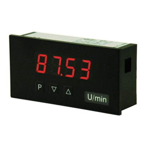
- Page 1 Operating Instructions Digital Indicating Unit for Panel Mounting Thermoelements Model: DAG-A1T...
-
Page 2: Table Of Contents
Error elimination ..................18 Disposal ...................... 19 EU Declaration of Conformance ..............20 Manufactured and sold by: Kobold Messring GmbH Nordring 22-24 D-65719 Hofheim Tel.: +49(0)6192-2990 Fax: +49(0)6192-23398 E-Mail: info.de@kobold.com Internet: www.kobold.com page 2 DAG-A1T K05/0722... -
Page 3: Note
Please read these operating instructions before unpacking and putting the unit into operation. Follow the instructions precisely as described herein. The instruction manuals on our website www.kobold.com are always for currently manufactured version of our products. Due to technical changes, the instruction manuals available online may not always correspond to the product version you have purchased. -
Page 4: Short Description
DAG-A1T 5. Short description The panel instrument DAG-A1T is a 4-digit device for temperature metering via thermocouple and a visual limit value monitoring via the display. The configuration happens via three front keys. An integrated programming interlock prevents unrequested changes of the parameter and can be unlocked again via an individual code. -
Page 5: Electrical Connection
DAG-A1T 7. Electrical Connection Type DAG-A1T3000R with a supply of 24 VDC Advice: The galvanic insulation in devices with temperature sensors that do not have a galvanic connection to an extrinsic potential, can be cancelled by a bridge from terminal 3 to 4 and thus stabilise the device against external failures. -
Page 6: Function Description And Operation
Change to parameterization level with the relevant parameters Menu level For navigation at the menu level To confirm the changes made at the parameterization level Parameterization level To change the value or setting Example: Menu level Parameterization level page 6 DAG-A1T K05/0722... -
Page 7: Setting Up The Device
DAG-A1T 9. Setting up the device 9.1 Switching on Once the installation is complete, you can start the device by applying the current loop. Check beforehand once again that all the electrical connections are correct. Starting sequence For 1 second during the switching-on process, the segment test (8 8 8 8 8) is displayed, followed by an indication of the software type and, after that, also for 1 second, the software version. -
Page 8: Programming Interlock Run
9.3 Programming interlock RUN 9.4 Extended parameterization By pressing the [▲] & [▼] buttons during standard parameterization for one second, the display switches to the extended parameterization mode. Operation is the same as in standard parameterization. page 8 DAG-A1T K05/0722... - Page 9 DAG-A1T DAG-A1T K05/0722page 9...
- Page 10 DAG-A1T page 10 DAG-A1T K05/0722...
-
Page 11: Reset To Default Values
DAG-A1T 10. Reset to default values To return the unit to a defined basic state, a reset can be carried out to the default values. The following procedure should be used: Switch off the power supply Press button [P] Switch on voltage supply and press [P]-button until „- - - -“ is shown in the display. -
Page 12: Functional Principle Of The Switching Point
An activated set point can be optically indicated by flashing of the 7-segment display. Functional principle of the alarms Alarm Deactivated, display value Threshold Threshold/limit value for switch over Hysteresis Width of the window between the thresholds Operating principle Limit value exceedance / limit value undercut page 12 DAG-A1T K05/0722... -
Page 13: Technical Information
DAG-A1T 12. Technical Information Housing Dimensions 48x24x27 mm (BxHxD) 48x24x54 mm (BxHxD) including plug-in terminal Panel cut-out 45.0 +0.6 x 22.20 +0.3 Insulation thickness up to 3 mm Fixing snap-in screw element Material PC Polycarbonate, black, UL94V-0 Sealing material EPDM, 65 Shore, black... - Page 14 Ambient conditions Working temperature 0°C…60°C Storing temperature -20°C…80°C Weathering resistance relative humidity 0-80% on years average without dew EN 61326 CE-sign Conformity to directive 2014/30/EU Safety standard According to low voltage directive 2014/35/EU EN 61010; EN 60664-1 page 14 DAG-A1T K05/0722...
-
Page 15: Order Codes
13. Order Codes STANDARD TYPES ORDER NUMBER Thermocouple Housing size: 48x24 mm DAG-A1T3000R Options – breakdown of order code: DAG-A1T 3 0 0 0 R Supply 3 = 24 VDC, galvan. isolated Output 0 = without Sensor supply 0 = without... -
Page 16: Safety Advice
• endanger human life and/or can destroy the equipment. The terminal area of the devices is part of the service. Here electrostatic • discharge needs to be avoided. Attention! High voltages can cause dangerous body currents. page 16 DAG-A1T K05/0722... - Page 17 DAG-A1T Galvanic isolated potentials within one complex need to be placed on an • appropriate point (normally earth or machines ground). So, a lower disturbance sensibility against impacted energy can be reached and dangerous potentials, that can occur on long lines or due to faulty wiring, can be avoided.
-
Page 18: Error Elimination
• Please check the possibility to set aside the galvanic isolation for a discharging of failures as described under chapter 7 „Electrical connection“. Before make sure that the possible metal sensor is separated from the sensor element. page 18 DAG-A1T K05/0722... -
Page 19: Disposal
DAG-A1T 16. Disposal Note! Avoid environmental damage caused by media-contaminated parts Dispose of the device and packaging in an environmentally friendly manner Comply with applicable national and international disposal regulations and environmental regulations. Batteries Batteries containing pollutants are marked with a sign consisting of a crossed-out... -
Page 20: Eu Declaration Of Conformance
DAG-A1T 17. EU Declaration of Conformance We, KOBOLD Messring GmbH, Hofheim-Ts, Germany, declare under our sole responsibility that the product: Digital Indicating Unit for Panel Mounting Model: DAG-A1T to which this declaration relates is in conformity with the standards noted below:...
Need help?
Do you have a question about the DAG-A1T and is the answer not in the manual?
Questions and answers