Table of Contents
Advertisement
Quick Links
Advertisement
Table of Contents

Subscribe to Our Youtube Channel
Related Manuals for Monoprice Blackbird 27842


Summary of Contents for Monoprice Blackbird 27842
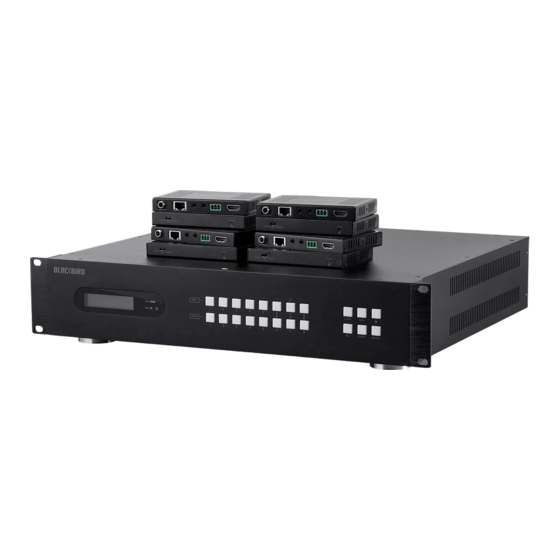
- Page 1 Blackbird™ 4K HDBaseT™ 8x8 HDMI® Matrix P/N 27842 User's Manual...
-
Page 2: Table Of Contents
CONTENTS SAFETY WARNINGS AND GUIDELINES ............................4 INTRODUCTION ........................................ 5 FEATURES ..........................................6 CUSTOMER SERVICE ....................................6 PACKAGE CONTENTS ....................................7 PRODUCT OVERVIEW ....................................7 Matrix Front Panel ....................................7 Matrix Rear Panel ..................................... 8 Receiver Front Panel ..................................... 9 Receiver Rear Panel ..................................... - Page 3 EDID Copy Configuration Screen ............................23 EDID Setting Configuration Screen ............................23 HDMI Input CEC Screen .................................. 24 HDBT Output CEC Screen ................................25 HDMI Output CEC Screen ................................25 RS232 Screen ......................................26 Access Screen ......................................27 Interface Screen ..................................... 28 Network Screen .....................................
-
Page 4: Safety Warnings And Guidelines
TECHNICAL SUPPORT ....................................46 SPECIFICATIONS ......................................46 Matrix ..........................................46 Receivers ........................................47 SAFETY WARNINGS AND GUIDELINES Please read this entire manual before using this device, paying extra attention to these safety warnings and guidelines. Please keep this manual in a safe place for future reference. ... -
Page 5: Introduction
Take care to prevent damage to the power cord. Do not allow it to become crimped, pinched, walked on, or become tangled with other cords. Ensure that the power cord does not present a tripping hazard. Never unplug the unit by pulling on the power cord. Always grasp the connector head or adapter body. -
Page 6: Features
If you have any problem with your order, please give us an opportunity to make it right. You can contact a Monoprice Customer Service representative through the Live Chat link on our website www.monoprice.com during normal business hours (Mon-Fri: 5am-7pm PT, Sat-Sun: 9am-... -
Page 7: Package Contents
PACKAGE CONTENTS Please take an inventory of the package contents to ensure you have all the items listed below. If anything is missing or damaged, please contact Monoprice Customer Service for a replacement. 1x HDBaseT™ 8x8 HDMI® matrix 16x Receiver mounting ear screws... -
Page 8: Matrix Rear Panel
3. IR: The LED illuminates red when the matrix receives an IR signal from the included IR remote control. The IR receiver "eye" is to the right of the LED. 4. INPUT: Eight buttons for input source selection. Button 7 also serves as the UP navigation button. -
Page 9: Receiver Front Panel
2. AUDIO OUT: Eight 3-pin terminal blocks for analog audio output and eight coaxial jacks for separating the digital audio from the HDMI inputs and HDBaseT™ outputs using the GUI. 3. OUTPUT: Eight sets of RJ45 jacks and HDMI® ports for connecting the included HDBaseT™... -
Page 10: Receiver Rear Panel
2. POWER: The LED illuminates red when power is applied. Receiver Rear Panel 1. HDMI OUT: HDMI® port for connecting an HDMI display. 2. RS232: 3-pin terminal block for connecting an RS-232 control or pass-through device. 3. IR IN: 3.5mm jack for connecting an IR receiver. 4. -
Page 11: Remote Control
Remote Control 1. POWER: Press the POWER button to turn the matrix on or to put it into standby mode. 2. LED: The LED flashes when a button is pressed. 3. INPUTS: Buttons for selecting the input source. 4. OUTPUTS: Buttons for selecting the output channel. 5. -
Page 12: Sample Connection Diagram
SAMPLE CONNECTION DIAGRAM IR PASS-THROUGH The system supports bi-directional IR pass-through, allowing you to control devices on both the source and destination ends. This section provides several connection and switching examples to illustrate possible configurations. The kit comes with eight IR receivers and eight IR transmitters. - Page 13 For example, if HDMI® input 3 is connected to the HDBaseT™ output 4, plug an IR receiver into the IR IN 4 jack and an IR transmitter into IR OUT 3, as shown in the diagram below. The same standard applies when you have one HDMI® input connected to multiple HDBaseT™...
-
Page 14: Control Local Input Device From Remote
Control Local Input Device From Remote The same basic principle applies when controlling the local input device from the remote location. For example, if you have HDMI® input 3 connected to HDBaseT™ output 4, plug an IR receiver into the IR IN jack on the receiver, then plug an IR transmitter into IR OUT 3 on the matrix, as shown in the diagram below. -
Page 15: Control Remote Device From Local
Control Remote Device From Local You can also control the remote display from the local end. For example, if you have HDMI® input 3 connected to HDBaseT™ output 3, plug an IR receiver into the IR IN 3 jack on the matrix, then plug an IR transmitter into the IR OUT jack on the receiver, as shown in the diagram below. -
Page 16: Button Control
BUTTON CONTROL The matrix can be controlled using the buttons on the front panel. Whenever a command is accepted by the matrix, all the buttons pressed will blink 3 times, then will turn off. If the command fails, the indicators in the buttons will turn off immediately without blinking. Switching To make a single, one-on-one connection, press an INPUT button, then press an OUTPUT button, and finally press the ENTER button. - Page 17 By default, the matrix will use the EDID information from the display connected to output 1, but it may have a higher maximum resolution than another connected display, which would prevent the other display from displaying video. To overcome this problem, this matrix includes advanced EDID management.
-
Page 18: Inquiry Mode
4K@60Hz 4:2:0 PCM, Dolby®, DTS® 4K@60Hz 4:4:4 PCM, Dolby, DTS To assign one of the predefined EDID settings to one source device, first press and hold the EDID button for 3 seconds, then press an INPUT button, then use the LEFT (OUTPUT 6) and RIGHT (OUTPUT 8) buttons to select one of the presets, and finally press the ENTER button to confirm. -
Page 19: Recall Preset
LCD Screen Description 01 02 03 04 Reports the signal switching status. 05 05 05 05 Reports the HDCP compliance status of all inputs. Y 1 2 3 4 means the input AV signal has HDCP data and N Y Y N N HDCP means that it does not. -
Page 20: Gui Control
GUI CONTROL You can control the matrix using a web-based Graphical User Interface (GUI) by plugging an Ethernet cable into the TCP/IP jack on the matrix, then plugging the other end directly into your computer or into a switch or router on an existing Ethernet network. The matrix has the following default IP settings: IP Address: 192.168.0.178... -
Page 21: Switching Screen
Switching Screen The 8x8 Input/Output grid allows you to specify an individual Input for each Output. Click the individual buttons in the grid to make a specific connection. For example, to connect output 2 to input 1, click the button at the junction of the Output 2 column and the Input 1 row. -
Page 22: Audio Screen
Audio Screen The Audio screen allows you to determine the source of digital audio on each of the eight coaxial audio jacks on the rear panel. Each output can be set to use the audio stripped from the corresponding numbered HDMI® source device or the corresponding HDBaseT™ output. -
Page 23: Edid Copy Configuration Screen
EDID Copy Configuration Screen The EDID Copy tab on the Configuration screen allows you to copy the EDID information from a display connected to one of the outputs to one or more of the HDMI® inputs. To copy the EDID, first click one or more of the buttons in the Input columns. Alternatively, click the All button to select all Inputs. -
Page 24: Hdmi Input Cec Screen
To assign one of the predefined EDID settings to one or more inputs, first click the buttons in the Input columns. Alternatively, click the All button to select all Inputs. Next, click the drop-down list box and click on one of the options. Finally, click the Confirm button to make the change or the Cancel button to abort the change. -
Page 25: Hdbt Output Cec Screen
HDBT Output CEC Screen The HDBT Output tab of the CEC screen allows you to control the display connected to one of the HDBaseT™ receivers. To control the display connected to one of the HDBaseT receivers, first click the button in the Output columns corresponding to the display you want to control. -
Page 26: Rs232 Screen
To control one of the displays connected to one of the local HDMI® outputs, first click the button in the Output columns corresponding to the display you want to control. Next, click CEC BUTTONS any of the buttons on the right to issue the indicated command. Refer to the section for an explanation of the meaning of each of the icons used on the buttons. -
Page 27: Access Screen
Access Screen The Access screen allows you to set the passwords, lock the front panel controls, and view the GUI and firmware version numbers. The default passwords are admin and user. To change either password, click inside the field and type a new password, then click the Confirm button to save the change or the Cancel button to abort the change. -
Page 28: Interface Screen
Interface Screen The Interface screen allows you to change various text labels. For example, you may want to change the name for Input 1 to DVD, so that you don't have to remember that Input 1 is the DVD player. To change one or more labels, click in the appropriate field(s) and type in the new label, then click the Confirm button to save the changes or the Cancel button to abort the changes. -
Page 29: Cec Buttons
To change the network protocol, click on either the DHCP or Static IP side of the network protocol control, then click the Confirm button to save the changes. To change the IP Address, Subnet Mask, or Gateway, click in the field and type in a new address, then click the Confirm button to save the changes. -
Page 30: Gui Update
Down Left Right Enter Exit Mute GUI UPDATE In the event that a firmware update is available, you can update the matrix using the built- in update GUI. To access the GUI, type 192.168.0.178:100 into the address bar of a web browser. -
Page 31: Rs-232 Control
RS-232 CONTROL Control Matrix From Local To control the matrix from a local PC, plug one end of the included 3-pin to DB9 RS-232 Cable into the RS232 connector on the rear panel, then plug the other end into an available serial port on your PC, as shown in the diagram below. -
Page 32: Control Remote Third Party Device From Local
Control Remote Third Party Device From Local To control a third party device from local, first determine which HDBaseT™ receiver it is connected to (1 in the diagram below). Next, use one of the included 3-pin Terminal Blocks to make a serial cable, plug one end into the RS232 connector on the HDBaseT receiver, then plug the other end into the serial port on your third party device. -
Page 33: Rs-232 Commands
RS-232 COMMANDS This switch features an RS-232 connector with the ability be controlled by a third party RS- 232 control software, as well as to pass RS-232 control signals through to a third party device. It supports serial communications rates of 2400, 4800, 9600 (default), 19200, 38400, 57600, or 115200 baud. -
Page 34: System Commands
The matrix can respond to the following RS-232 commands: System Commands Command Function Feedback /*Type; Report matrix model 27842 /*Name; Report matrix name HDBaseT Matrix /%Lock; Lock the front panel buttons System Locked! /%Unlock; Unlock front panel buttons System Unlock! /^Version;... - Page 35 Command Function Feedback Demo Mode AV:01->01 IR:01->01 Switch to demo testing mode, AV:01->02 Demo. switch AV 1->2, 2->2, etc. IR:01->02 AV:08->08 IR:08->08 Undo. Cancel the previous operation Undo Ok! PWON. Power the system on PWON PWOFF. Power the system off PWOFF STANDBY.
-
Page 36: Signal Switching
Signal Switching Command Function Feedback Switch input [x] AV to all [x]All. 01 To All. outputs. x=1~8. Switch all input signals to their All#. corresponding output channels. All Through. 1->1, 2->2, 3->3, 4->4, 5->5... All$. Switch off all outputs All Closed. Switch input [x] to output [x]. - Page 37 Command Function Feedback AV:01->01 IR:01->01 AV:02->02 IR:02->02 Report the input channel on Status. AV:03->03 output channels, on by one. IR:03->03 AV:08->08 IR:08->08 Report the connection status of all inputs. Y means the In 1 2 3 4 5 6 7 8 %9971.
-
Page 38: Preset Management
Preset Management Command Function Feedback Store the current switch status Save[y]. Save To F3 to preset [y]. y=1~9. Recall[y]. Recall preset [y]. y=1~9. Recall From F1 Clear[y]. Clear preset [y]. y=1~9. Clear F1 Output Audio Control Command Function Feedback Mute or unmute the coaxial COAX[x][MU/UM]. -
Page 39: Edid Configuration
EDID Configuration Command Function Feedback Set the EDID data of output [x] to input [y]. If the EDID data is available and the audio part supports not only PCM format, EDIDH[x]B[y]. EDIDH1B4 then force-set it to only support PCM. If the EDID is not available, this will set to initial EDID. - Page 40 Command Function Feedback The input [x] recalls the preset EDID [y]. x=1~8, y=1~7. 1. 720p 2D PCM/Dolby®/DTS® 2. 720p 3D PCM/Dolby/DTS 3. 1080p 2D PCM/Dolby/DTS EDID/[x]/[y]. EDIDIN/1/0 4. 1080p 2D PCM/Dolby/DTS 5. 4K@30Hz PCM/Dolby/DTS 6. 4K@60Hz 4:2:0 PCM/Dolby/DTS 7. 4K@60Hz 4:4:4 2D PCM/Dolby/DTS Upgrade the embedded EDID [y].
-
Page 41: Hdcp Compliance
HDCP Compliance Command Function Feedback HDCP management command. The O is the output port, X is /%O/[X]:[Z]. the number of the output port, /%O/1:1. and Z is for HDCP compliance status. X=01~08 or ALL, Z=0~1. %0801. Auto HDCP management mode. 0801% Report the HDCP status of all inputs. -
Page 42: Baud Rate Setting
Baud Rate Setting To ensure bi-directional RS-232 communications, the serial baud rate of the matrix should be set the same as the RS-232 ports on the HDBaseT™ receivers. Command Function Feedback Set the serial baud rate of the Set Local RS232 Baudrate 2400. - Page 43 The [I] in the command represents the input port. The [O] in the command represents the output port. The [port] in the command represents the port number. The local HDMI® output ports are 01~08 and the HDBT output ports are 00, 0A, 0B, 0C, 0D, 0E, 0F, and 0G. The HDMI input ports are 01~08.
-
Page 44: Troubleshooting
Command Function Feedback CECI[port]4B. Forward CEC_IN_01_SEND_SUCCESS! CECI[port]4C. Backward CEC_IN_01_SEND_SUCCESS! CECI[port]6C. Power off CEC_IN_01_SEND_SUCCESS! CECI[port]6D. Power on CEC_IN_01_SEND_SUCCESS! Output Control Commands: Command Function Feedback CECO[port]41. Volume up CEC_OUT_01_SEND_SUCCESS! CECO[port]42. Volume down CEC_OUT_01_SEND_SUCCESS! CECO[port]43. Mute CEC_OUT_01_SEND_SUCCESS! CECO[port]6C. Power off CEC_OUT_01_SEND_SUCCESS! CECO[port]6D. Power on CEC_OUT_01_SEND_SUCCESS! TROUBLESHOOTING Problem... - Page 45 Problem Potential Causes Potential Solutions Use an oscilloscope or No signal at the input / multimeter to verify there is output end. a signal at the input / No output image when output end. switching. Ensure the connection is Failed or loose connection. good.
- Page 46 TECHNICAL SUPPORT Monoprice is pleased to provide free, live, online technical support to assist you with any questions you may have about installation, setup, troubleshooting, or product recommendations. If you ever need assistance with your new product, please come online to talk to one of our friendly and knowledgeable Tech Support Associates.
- Page 47 Audio Output Impedance 70 ohms Frequency Response 20 Hz ~ 20 kHz ±3dB Common Mode Rejection Ratio (CMRR) >70dB @ 20 Hz ~ 20 kHz Signal-to-Noise Ratio 100dB Input Power 100 ~ 240 VAC, 50/60 Hz Maximum Power Consumption 100 watts Operating Temperature +14 ~ +131°F (-10 ~ +55°C) Storage Temperature...
- Page 48 4.5" x 0.6" x 3.3" (115 x 16 x 84 mm) Weight 5.4 oz. (153 g) Blackbird™ is a trademark of Monoprice Inc. HDMI®, the HDMI Logo, and High-Definition Multimedia Interface are trademarks or registered trademarks of HDMI Licensing LLC in the United States and other countries.
Need help?
Do you have a question about the Blackbird 27842 and is the answer not in the manual?
Questions and answers