Table of Contents
Advertisement
Quick Links
Advertisement
Table of Contents

Related Manuals for Monoprice 27842


Summary of Contents for Monoprice 27842
- Page 1 8x8 HDMI 2.0 HDBaseT Matrix Switcher P/N 27842 User's Manual...
-
Page 2: Table Of Contents
CONTENTS SAFETY WARNINGS AND GUIDELINES ........................4 INTRODUCTION ................................5 FEATURES ..................................5 CUSTOMER SERVICE ..............................6 PACKAGE CONTENTS..............................7 SPECIFICATIONS ................................8 Matrix Switcher ................................ 8 HDBaseT Receiver ..............................9 PRODUCT OVERVIEW ..............................11 Matrix Switcher Front Panel ............................. 11 Matrix Switcher Rear Panel ............................ - Page 3 RS232 Commands ..............................42 FIRMWARE UPGRADE ..............................56 PANEL DRAWING ............................... 57 TROUBLESHOOTING ..............................58 TECHNICAL SUPPORT ..............................58 REGULATORY COMPLIANCE ..........................59 Notice for FCC ..............................59 Notice for Industry Canada ............................ 59...
-
Page 4: Safety Warnings And Guidelines
SAFETY WARNINGS AND GUIDELINES Please read this entire manual before using this device, paying extra attention to these safety warnings and guidelines. Please keep this manual in a safe place for future reference. This device is intended for indoor use only. ... -
Page 5: Introduction
INTRODUCTION Thanks for choosing the professional 8x8 HDMI 2.0 HDBaseT matrix switcher! The matrix is an eight-input by eight-output HDBaseT and HDMI matrix with HDCP 2.2 and up to 4K/UHD@60Hz video support. It transmits 4K video to distances up to 131 feet (40 meters) and 1080p video to distances up to 230 feet (70 meters) over a single CATx Ethernet cable. -
Page 6: Customer Service
If you have any problem with your order, please give us an opportunity to make it right. You can contact a Monoprice Customer Service representative through the Live Chat link on our website www.monoprice.com during normal business hours (Mon-Fri: 5am-7pm PT, Sat-Sun: 9am-6pm PT) or via email at support@monoprice.com... -
Page 7: Package Contents
PACKAGE CONTENTS Please take an inventory of the package contents to ensure you have all the items listed below. If anything is missing or damaged, please contact Monoprice Customer Service for a replacement. 1x 27842 8x8 HDMI 2.0 HDBaseT Matrix Switcher ... -
Page 8: Specifications
SPECIFICATIONS Matrix Switcher Video Input Input (8) HDMI Input Connector (8) Type-A female HDMI HDMI Input Resolution Up to 4Kx2K@60Hz 4:4:4, HDR10,1080p 3D Video Output Output (8) HDBaseT, (8) HDMI Output Connector (8) RJ45, (8) Type-A female HDMI Up to 4Kx2K@60Hz 4:4:4, HDR10, 1080p 3D. HDMI Output Resolution Supports 4K to 1080p down-scaling. -
Page 9: Hdbaset Receiver
L+R: < -80 dB, 10KHz sine at 0dBFS level (or max level before clipping). L+R: < 0.3dB, 1KHz sine at 0dBFS level (or max level before L-R Level Deviation clipping). Frequency Response < ± 0.5dB 20Hz - 20KHz. Deviation Output Load Capability L+R: 1KΩ... - Page 10 Input Connector (1) Toslink Connector Output (1) Audio Breakout Output Connector (1) Toslink connector Audio Format Supports PCM, Dolby Digital, Dolby True-HD, DTS and DTS-HD. Frequency Response 20Hz – 20KHz, ± 3dB 2.0Vrms ± 0.5dB. 2V = 16dB headroom above -10dBV (316mV) Max Output Level nominal consumer line level signal <...
-
Page 11: Product Overview
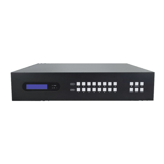
PRODUCT OVERVIEW Matrix Switcher Front Panel INPUT MENU/ PRESET BACK DOWN ① LCD Screen: Presents real-time operation status. ② Power LED: Illuminates RED when the device is in standby mode, illuminates GREEN when device is powered on. ③ IR Sensor and its LED: Illuminates RED when the IR sensor receives an IR signal from the IR remote to control the matrix switcher. -
Page 12: Matrix Switcher Rear Panel
Matrix Switcher Rear Panel ALL IN ALL OUT RS232 IR EYE TCP/IP ① INPUT: Eight type-A female HDMI input ports to connect HDMI sources. ② AUDIO MATRIX OUT/ARC: Eight 3-pin terminal blocks and eight Toslink connectors to connect speakers or amplifiers for HDMI input audio de-embedding or HDBaseT output audio de-embedding, and the eight Toslink connectors can also be used for ARC audio output from HDBaseT receivers. -
Page 13: Receiver Front And Rear Panel
1~8: Eight 3.5mm jacks to connect eight IR emitters to send the IR signal received from the corresponding HDBaseT receivers. ALL OUT: 3.5mm jack to connect the IR emitter to send the IR signal received from all HDBaseT receivers. ⑧... -
Page 14: System Connection
SYSTEM CONNECTION Usage Precaution Make sure all components and accessories included before installation. System should be installed in a clean environment with proper temperature and humidity. All of the power switches, plugs, sockets, and power cords should be insulated and safe. ... -
Page 15: Button Control
BUTTON CONTROL The matrix switcher can be controlled by using the buttons on the front panel. Whenever a command is accepted, the indicators of all the buttons pressed will blink three times then they will go off. If the command fails, the indicators will go off immediately without blinking. Signal Switching Switch an input to an output ... -
Page 16: Status Information Inquiry
Status Information Inquiry Status Info < EDID Management Press Press enter status information tab. Press navigation buttons to check the previous or next item respectively. LCD Screen Description Report the signal switching status. Report the connection status of all HDMI input ports. LINK Y means the corresponding input port is connected to a source device, N means there is no connection between the input port... -
Page 17: Edid Management
EDID Management The Extended Display Identification Data (EDID) is used by the source device to match its video resolution with the connected display. By default, the eight source devices invoke the fifth built-in EDID: 4K@60Hz HDR 2CH. Enter EDID management tab: ... -
Page 18: Audio Setting
To invoke the built-in EDID data: There are six types of built-in EDID data can be invoked, as shown as below: EDID Video Audio 1080p 1080p HDR MultiCH 4K@30Hz HDR 4K@60Hz HDR MultiCH 5 (Default) 4K@60Hz HDR 4K@60Hz HDR MultiCH User Custom Example: Input 1 and 2 invoke the built-in EDID data: 4K@30Hz HDR 2CH. - Page 19 L+R OUT 7 In7 Breakout Out7 Breakout In8 Breakout Out8 Breakout L+R OUT 8 SPDIF OUT 1 In1 Breakout Out1 Breakout Out1 ARC SPDIF OUT 2 In2 Breakout Out2 Breakout Out2 ARC SPDIF OUT 3 In3 Breakout Out3 Breakout Out3 ARC SPDIF OUT 4 In4 Breakout Out4 Breakout...
-
Page 20: Preset Setting
Preset Setting Press PRESET button can save the current switching routing or load the saved layout preset. Note: The matrix switcher supports nine presets, but only preset 1~4 can be saved and recalled by button control. Please manage other preset by GUI control or RS232 control. Save the current switching routing to a preset ... -
Page 21: Gui Control
GUI CONTROL The switcher can also be controlled via TCP/IP. The default IP settings are: IP Address: 192.168.0.178 Subnet Mask: 255.255.255.0 Type 192.168.0.178 in the internet browser, it will enter the below log-in webpage: Username: admin Password: admin Type the user name and password, and then click Login to enter the section for video switching. -
Page 22: Signal Switching
Signal Switching Use the 8x8 button grid on the page to set which inputs are directed to which outputs. For example, clicking the button on the Input 1 row and Output 1 column, directs input 1 to output 1. Use the 9 numbered buttons under scene area to save and load layout presets. ... -
Page 23: Audio Setting
Audio Setting Audio Source Selection There are sixteen audio sources can be selected for eight analog L+R audio output ports, and twenty-four audio sources can be selected for eight digital SPDIF output ports. L+R Output Audio Volume Control ... -
Page 24: Configuration
Configuration Down-scaling Enable/disable video resolution down-scaling function of HDMI output 1~8 ports. When enable down-scaling, the 4K input can be automatically degraded to 1080p output for compatibility with 1080p display which is connected to the HDMI output port. HDCP Setting ... - Page 25 Set the HDCP mode of HDMI and HDBaseT outputs to Passive or Active. Mode Description Passive Automatically follows the HDCP version of source device. If the input video has HDCP content, the HDCP version of HDMI output is HDCP 1.4 for broader video solution. Active (Default) If the input video has no HDCP content, the HDMI output has ...
- Page 26 EDID Setting Click EDID Setting to enter the below section to set a predefined EDID for input ports. Select a built-in EDID for one or several input ports. Operation: 1) Select a built-in EDID. 2) Select one or several input ports. Press ALL to select all input ports. 3) Click Confirm to save setting.
-
Page 27: Cec Control
CEC Control If the input source devices, HDBaseT output devices and local HDMI output devices support CEC, they can be controlled via the following CEC interface. Input Source Device Control Select one or several HDMI input source devices to be controlled, and then press function ... -
Page 28: Rs232 Control
Select one or several HDBaseT or HDMI output devices to be controlled, and then press function buttons. RS232 Control Send RS232 commands to control third-party devices which are connected to the far-end HDBaseT receivers. Operation: 1) Select the HDBaseT port which is connected to HDBaseT receiver which must have third-party device attached. -
Page 29: Access Setting
Access Setting Reset the login admin and user password. Lock or unlock the front panel buttons. Get the GUI and firmware version. Click Confirm to save any changes or click Cancel to cancel any changes that have been made. -
Page 30: Interface Setting
Interface Setting Modify title bar label, LCD readout and button labels. Click Confirm to save any changes or click Cancel to cancel any changes that have been made. Network Setting Static IP or Dynamic Host Configuration Protocol (DHCP). ... -
Page 31: Gui Upgrade
Modify the static IP Address, Subnet Mask, and Gateway. GUI Upgrade Please visit at http://192.168.0.178:100 for GUI online upgrade. Type the username and password (the same as the GUI log-in setting, modified password will be available only after rebooting) to login the configuration interface. After that, click Administration in the source menu to get to Upload Firmware as shown below: Select the update file and click Apply button, and then it will start upgrade process. -
Page 32: Ir Control
IR CONTROL IR Remote Control The matrix switcher has a built-in IR sensor on the front panel for receiving IR control signal from IR remote. In addition, it also provides IR EYE port on the rear panel to connect an external IR receiver for IR local control. -
Page 33: Ir Pass-Through Control
IR Pass-through Control The matrix switcher supports bi-directional IR pass-through, allowing the devices can be controlled by both source and destination ends. This section provides connection and switching examples to illustrate possible configurations. Control Local Input Device from Remote The same basic principle applies when controlling the local input device from the remote location. - Page 34 Control local input device through IR ALL OUT port The emitter can be connected to the IR ALL OUT port on matrix switcher to control all local input devices. In this case, the IR receiver must be connected to the IR IN port on each connected HDBaseT receiver, as shown in the diagram below: HDMI: HDBaseT:...
- Page 35 Control Remote Output Device from Local The remote displays can be controlled from the local matrix switcher location. Control remote device through IR IN port Example: Switch HDMI input 3 to HDBaseT output 3. Connect an IR receiver to IR IN 3 port on the matrix switcher, then connect an IR emitter to the IR OUT on the receiver, as shown in the diagram below: HDMI: HDBaseT:...
- Page 36 Control remote device through IR ALL IN port The receiver can be connected to the IR ALL IN port on matrix switcher to control all remote output devices. In this case, the IR emitter must be connected to the IR OUT port on each connected HDBaseT receiver, as shown in the diagram below: IR Receiver Display Remote...
-
Page 37: Rs232 Control
RS232 CONTROL RS232 Control Connection Control the Matrix Switcher from Local To control the matrix switcher from a local PC, the 3-pin to DB9 RS232 Cable is used to connect between the matrix and PC. The connection diagram is shown as below: RS232: RS232 IR EYE... - Page 38 Control the Matrix Switcher from Remote To control the matrix switcher from remote location, please connect one or more PCs to the RS232 ports of HDBaseT receivers with the 3-pin to DB9 RS232 Cables. The matrix switcher can be controlled by any one of PCs, the connection diagram is shown as below: HDMI: RS232: HDBaseT:...
- Page 39 Control the Remote Third-party Device from Local To control a third-party device from local, first determine which HDBaseT receiver is connected to (1 in the diagram below). Next, connect a PC to the corresponding RS232 port of matrix switcher with 3-pin to DB9 RS232 Cable, then connect a third-party device (e.g. projector) to the RS232 port of the determined HDBaseT receiver.
- Page 40 Control the Local Third-party Device from Remote To control a third-party device from remote, first determine which HDBaseT receiver is connected to (1 in the diagram below). Next, connect a PC to the RS232 port of HDBaseT receiver with 3-pin to DB9 RS232 Cable, then connect a third-party device (e.g. projector) to the RS232 port of matrix switcher.
- Page 41 RS232 Control Software If the matrix switcher and third-party devices needs to be controlled from PC by an RS232 connection, a RS232 control software should be installed in PC. Here using CommWatch.exe as an example. The icon is shown as below: Double-click the icon to run, and its interface is depicted below: Parameter configuration area.
-
Page 42: Rs232 Commands
Command Description Feedback Power on the system. Power ON! PowerON. PowerOFF. Power off the system. Power OFF! /*Name. Report product name. 27842 Report product model. HDBaseT Matrix /*Type. V1.0.0 Report software version. CPLD:V1.0.0 /^Version. VideoDriverVersion:V1.0.0 RST. Reset to factory default. - Page 43 Command Example and Command Description Feedback “[XX]=00” represents all HDMI HDMI OUT 02 Down Scale outputs. … … HDMI OUT 08 Down Scale DS00OFF. Disable the video resolution HDMI OUT 01 Down Scale down-scaling function of HDMI OFF! DS[XX]OFF. output [XX]. [XX]=00~08. The …...
- Page 44 Command Example and Command Description Feedback RS232 Remote 08 Control MCU OFF! IRRCM00ON. Enable the IR remote-control mode for HDBT output [XX] IR Remote 01 Control MCU that the matrix switcher can be controlled by the IR remote at IR Remote 02 Control MCU IRRCM[XX]ON.
- Page 45 Report the on/off status of all Turn ON Output 02! STA_POUT. outputs. … … Turn ON Output 16! GUI Or RS232 Query Status: HDBaseT Matrix 27842 V1.0.0 Power ON! HDBT Power ON! STA. Report all system status. Front Panel UnLock! Local RS232 Baudrate Is 9600! GUI_IP:192.168.0.178!
- Page 46 Signal Switching Command Description Command Example and Response Enable the IR switching to IRFVON. IR Follow Video ON! follow the video switching. Disable the IR switching to IR Follow Video OFF! IRFVOFF. follow the video switching. Switch video input [YY] to OUT01:04.
- Page 47 Command Description Command Example and Response Output 02 Switch To In 02! Local 02 IR Out Switch To Remote 02 IR IN! Output 03 Switch To In 02! Local 02 IR Out Switch To Remote 03 IR IN! Output 04 Switch To In 02! Local 02 IR Out Switch To Remote 04 IR IN! PresetSta01.
- Page 48 Command Command Description Example and Response In4 Breakout Out8 Breakout In5 Breakout Out1 ARC In6 Breakout Out2 ARC In7 Breakout Out3 ARC SPDIF Out 01 In8 Breakout Out4 ARC Switch To Video In Out1 Breakout Out5 ARC Out2 Breakout Out6 ARC Out3 Breakout Out7 ARC Out4 Breakout...
- Page 49 Command Command Description Example and Response Analog Out 01 Volume UnMute! … … Analog Out 08 Volume UnMute! Select audio source [YY] for analog L+R audio ANALOG01:04. output [XX]. [XX]=00~08, The “[XX]=00” represents all L+R audio outputs. [YY]=01~16. [YY] Audio Audio Source Source...
- Page 50 Command Command Description Example and Response Out 08! HDCP Setting Command Example and Command Description Response HDCP00MAT. The HDCP content of output [XX] follows OUT 01 HDCP MAT the HDCP version of display device. Display! [XX]=00~16. … … HDCP[XX]MAT. [XX]=00, represents all outputs.
- Page 51 Command Example and Command Description Response OUT 15 HDCP BYPASSS! OUT 16 HDCP BYPASSS! EDID Management Command Example and Command Description Response Reset factory default EDID to all input All Input EDID Set EDIDMInit. ports. Default! Upgrade the EDID data of the input port EDIDUpgrade01.
- Page 52 Command Example and Command Description Response 4K@60Hz HDR MultiCH User-defined EDID Input 03 EDID Upgrade OK By 01 Internal EDID! Report the EDID data from output [XX]. EDIDGOUT04. [XX]=01~16. [XX]=01~08, represents HDBT output EDIDGOUT[XX]. EDIDOUT04: 1~8. …… [XX]=09~16, represents HDMI output 1~8.
- Page 53 Third-party Device Control Command Description Command Example Send the ASCII command “xxx” to control /+3/01:123456. the far-end third-party device. xxx: ASCII string. The “[X]=1~7” represents the baud rate of third-party device. Send the ASCII command [X]=1, the baud rate is 2400 “123456.”...
- Page 54 Command Description Command Example [X]=1, the baud rate is 2400 The third-party device is [X]=2, the baud rate is 4800 connected to the far-end [X]=3, the baud rate is 9600 HDBaseT receiver of [X]=4, the baud rate is 19200 connecting the HDBT [X]=5, the baud rate is 38400 output 1 port.
- Page 55 Command Description Command Example and Response CECI0204440D. CECI[AA][BB][CC]0D. Exit menu. CEC Input 02 Send Success! CECI0204446D. CECI[AA][BB][CC]6D. Power on. CEC Input 02 Send Success! CECI0204446C. CECI[AA][BB][CC]6C. Power off. CEC Input 02 Send Success! Control the output display device: Command Description Command Example and Response CECO05404441.
-
Page 56: Firmware Upgrade
FIRMWARE UPGRADE Please follow the steps as below to upgrade firmware by the FW port on the rear panel: 1) Prepare the latest two upgrade files and rename them as “08010000.APP” and “08010000.APS” on PC. 2) Power off the switcher, and connect the FW port of switcher to the PC with USB cable. 3) Power on the switcher, and then the PC will automatically detect a U-disk named of “BOOTDISK”. -
Page 57: Panel Drawing
PANEL DRAWING INPUT MENU/ PRESET BACK DOWN 436.6 mm RS232 IR EYE TCP/IP ALL IN ALL OUT 27842 Matrix Switcher 140 mm 27842R HDBaseT Receiver... -
Page 58: Troubleshooting
RS232 port TECHNICAL SUPPORT Monoprice is pleased to provide free, live, online technical support to assist you with any questions you may have about installation, setup, troubleshooting, or product recommendations. If you ever need assistance with your new product, please come online to talk to one of our friendly and knowledgeable Tech Support Associates. -
Page 59: Regulatory Compliance
(1) this device may not cause harmful interference, and (2) this device must accept any interference received, including interference that may cause undesired operation. Modifying the equipment without Monoprice’s authorization may result in the equipment no longer complying with FCC requirements for Class B digital devices. In that event, your right to use the equipment may be limited by FCC regulations, and you may be required to correct any interference to radio or television communications at your own expense.
Need help?
Do you have a question about the 27842 and is the answer not in the manual?
Questions and answers