Table of Contents
Advertisement
Quick Links
Advertisement
Table of Contents

Summary of Contents for RTS SSA-324
- Page 1 SSA-324 System Interface (System to System Adapter) 9350697900 Rev G 11/2006...
-
Page 2: Proprietarynonce
OTICE The product information and design disclosed herein were originated by and are the property of Telex Communications, Inc. Telex reserves all patent, proprietary design, manufacturing, reproduction, use and sales rights thereto, and to any article disclosed therein, except to the extent rights are expressly granted to others. -
Page 3: Table Of Contents
TABLE OF CONTENTS PROPRIETARYNOnCE ........... . . COPYRIGHTNOTICE . - Page 4 R105 U102A TB1-1,2 UlOlA U202A TB1-5,6 U201A R205 Four JlOl SlOl S 105 S205 5201 S201 rFt%&TH-t wire Input Unbalanced Zin=lO k Switch Switch Nominal Buffed Test Amplifer Switch Pickoff SSA324 Block Diagram System Interface (System to System Interface) SSA324 User Manual UlOlB U103B U103A...
-
Page 5: Section 1; Description And Specifications
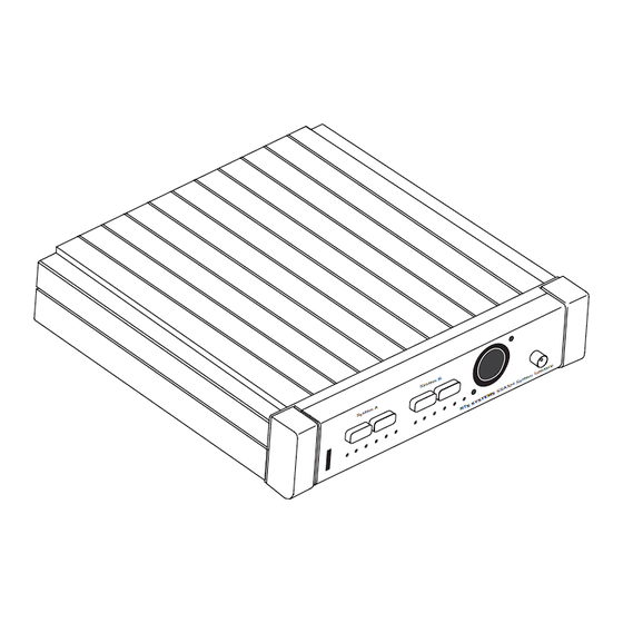
SECTION 1 : DESCRIPTION AND SPECIFICATIONS 1 . 1 DESCRIPTION (See Block Diagram, Figure 1-1) The Model SSA324 is a System to System Adapter (or inter- face). It interconnects the voice signals between different intercom systems. In addition, it can optionally interconnect "Calls"... - Page 6 Application The Model SSA324 aljplications include the following: 1Lterface audio signals between intercom systems Number of Channels Interfaced with the Model SSA324 by System McCurdy/ Generic 4W Interface (using optional plug in boards) the following non-audio signals: Audiocom call signal to Audiocom call signal. RTS Systems call signal to RTS Systems call signal.
- Page 7 1 3 . 1 ELECTRICAL SPECIFICATIONS (Specifications at 120VAC line voltage) Individual Interface Specification j 7 / (each of two dividual interfaces) Two-Wire Input Impedance:5,000 ohms +loo%, -20% single ended, 10,000 ohms +100%, -20% differential Operating Levels:-20 dBu to Two-Wire Output Impedance:5,000 ohms 20% single ended, 10,000 ohms 2Wo differential Operating Leve1s:O.l mA to 10 mA, nominal...
- Page 8 Figure 2-1 Rear Panel, Model SSA324 System Interface SSA324 User Manual...
-
Page 9: Section 2: Installation
SECTION INSTALLATION 2.1 MECHANICAL INSTALLATION The Model SSA324 can be installed in 3 ways: a single unit mounted in a half rack space using an optional Model MCP2 Kit for rack mounting a single unit; or two SSA324 supplies mounted side by side using the optional MCPl Kit for rack mounting two units side by side;... - Page 10 C" S y s t e m A S y s t e m B CHI-Out L e v e l N u \ \ . , , . I...
-
Page 11: Section S: Operation
SECTION 3: OPERATION 3.1 CONTROLS AND CONNECTORS F'ront Panel Switches Channel Select switch, CHl out Press momentary switch for nulling System A Two-wire. Channel Select switch, CHI out Press momentary switch for nulling System B Two-wire. XLR6-31 Female 6 pin headset connector (DYN MIC HEADSET) s A I &... - Page 12 SECTION 7: DIAGRAMS Document N u m b e r S i z e m Schematic Diagram- System To System Adapter, Model SSA324, Sht 1 of 3 SD6926 Schematic Diagram- System To System Adapter, Model SSA324, Sht 2 of 3 SD6926 Schematic Diagrarn- System To System Adapter, Model SSA324, Sht 3 of 3 SD6926...
- Page 13 +-WIRE 4-WIRE TRANSFORMERS T i 0 2 AND T202 NORMALLY NOT INSTALLED. TRANSFORMERS T l O l AND T201 NORMALLY NOT INSTALLED. TRANSFORMERS T I 0 3 AND T 2 0 3 NORMALLY NOT INSTALLED. CUT TRACES ON P.C.B. LAST USED: ~ 1 0 3 .
- Page 14 CALL SEND b > CONTRACT NO. Drown NOT USED: R226.R227 S205 CHI-OUT FRONT PANELCH~-*~ N.C. R T S SYSTEMS eurtmnk. c a l l t o r n l a SCHEMATIC DIAGRAM- SYSTEM TO SYSTEM ADAPTER. MODEL SSA324...
- Page 15 O P T I O N CAR0 & C A L L SENO GNO CALL SENO H I OC CALL S I G E N GNO (A) OC CALL S I G E N H I RELAY CONTACT NO & R E L A Y CONTACT NC (A) RELAY CONTACT RELAY CONTACT NO...
- Page 16 T I 0 1 AND T201 ARE OPTIONAL DO NOT INSTALL n o o o o o o o 0 0 0 0 0 0 0 0 0 0 0 0 m o o o o o o o o o o o o mmmmmmmmmmm CWSRW~34R259e236R253R2MlG82C244 uwwwmwumumm...


Need help?
Do you have a question about the SSA-324 and is the answer not in the manual?
Questions and answers