Page 1
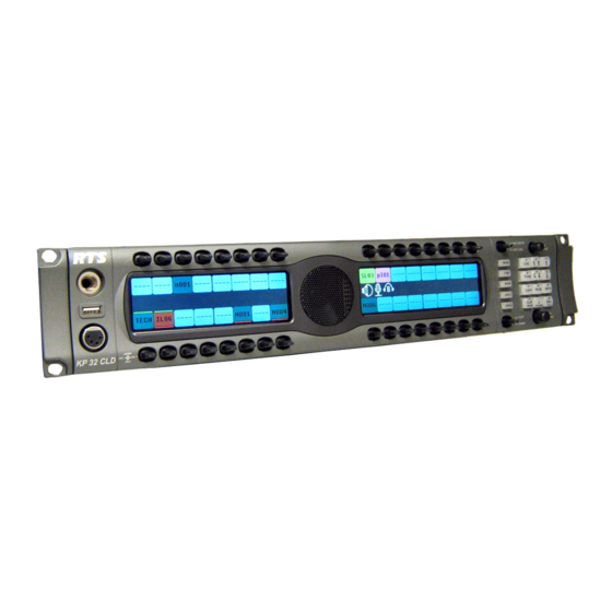
CLD Color Keypanel Family User Manual up to and including version 1.3.1 KP 32 CLD DKP 16 CLD EKP 32 CLD Rev. 10 JANUARY/2012 F.01U.193.294...
Page 2
For warranty and service information, refer to the appropriate web site below: WARNING: THE MAIN POWER PLUG MUST REMAIN READILY OPERABLE. RTS ..........www.rtsintercoms.com/warranty RTSTW ............. www.rtstw.com/warranty CAUTION: TO REDUCE THE RISK OF ELECTRIC SHOCK, GROUNDING OF THE CENTER PIN OF THIS PLUG MUST BE MAINTAINED.
Page 3
KP32CLD Important Safety Instructions Read these instructions. Keep these instructions. Heed all warnings. Follow all instructions. Do not use this apparatus near water. Clean only with dry cloth. Do not block any ventilation openings. Install in accordance with the manufacturer’s instructions. Do not install near any heat sources such as radiators, heat registers, stoves, or other apparatus (including amplifiers) that produce heat.
Page 4
KP32CLD Bosch Security Systems, Inc. Rev. 10 F.01U.193.294 User Manual...
Page 6
KP32CLD Key Gain Adjustment ..........................32 Listen Volume Adjustments ........................33 Aux Volume Adjustments ........................34 Operation of Intercom Keys with Auto Functions .................36 Operation of Intercom Keys with Options .....................36 Group Option Keys ............................36 Solo Key ................................36 Operation of Intercom Talk Keys with the Speaker DIM Setting ............36 Operation of Intercom Keys assigned to TIF Ports ................37 User Quick Select Scrolling ........................37 Call Waiting Operation ..........................38...
Page 7
KP32CLD Enable The Boot Loader On The Keypanel (v 1.1.0 and later) ................ 62 KP 32 CLD MENU SYSTEM ..................... 63 Main Menu Access ..........................63 Menu System, Audio Options ........................64 Audio Options Menu, Dim ..........................65 Audio Options Menu, DSP Funcs ........................66 Equalization ..............................
Page 8
Service Menu, Test Panel ..........................144 TELEPHONE OPERATION ....................147 Receiving A Phone Call ........................147 Dialing and Hanging Up Using KP 32 CLD ..................147 Manual Dial ..............................147 Keypanel Hang Up ............................148 Auto Dial ................................. 150 Centralized Auto Dials .........................151 Centralized Auto Dial from the KP 32 CLD ....................
Page 9
Dip Switches ............................187 Firmware Compatibility Requirements for the RVON-2 Card ............188 Installation of the RVON-2 Card ......................188 KP 32 CLD ..............................188 DKP 16 CLD ..............................191 Addresses and the RVON-2 .........................195 Configure the RVON-2 from the KP CLD ..................195 Set the IP Address from the Service Level Menu ......................
Page 10
KP32CLD CYRILLIC SUPPORT ......................219 AZedit and Cyrillic Support ........................219 User Manual F.01U.193.294 Bosch Security Systems, Inc. Rev. 10...
In addition, the CLD units can be ordered with the new, more intuitive CLD key sequences, or the classic key sequences. Like all RTS products, the CLD family of keypanels are designed with expansion in mind.
XLR(Female) Headset” on page 11 for pinouts). Input Sources USB Type A Panel Microphone / GPIO MIC IN DB-9, RJ-45 (Supports RTS RJ-11 cabling or Electric Microphone Input Level Keypanel Audio Standard Cat5 cabling) See “RJ-45 Frame (RTS Nominal Level Input / Output RJ11 Cable)”...
Matrix connection. Main Volume - Adjusts the volume for the front speaker, rear speaker, front headset and rear headset. Keypad - Navigates through the KP 32 CLD menu structure and configure keypanel features as well as utilize the TIF dial-out features.
Keypad - The keypanel keypad is used to navigate Menu button - For detailed explanation, see “KP 32 through the KP 32 CLD menu structure and configure CLD Menu System” on page 61. keypanel features as well as utilize the TIF dial-out FWD button - Allows you to go forward in the menu features.
Page 19
KP32CLD Introduction 9 DKP 16 CLD Front, Right and Left Side Views FIGURE 5. USB - Power-enabled USB connector. Can be used to charge a cell phone or download/upload data to or from the keypanel. 4-, 5-pin XLR(female) – Headset 6-, 7-pin XLR(female) –...
14 Introduction KP32CLD Accessing the Switch Bank To access the switch bank, do the following: Remove the four (4) screws on the top of the unit. In no certain order, remove the following screws. User Manual Bosch Security Systems, Inc. F.01U.193.294 Rev.
Page 25
KP32CLD Introduction 15 Carefully lift the chassis up and back to remove the back panel. Note, the back panel is still attached by the DB-9 frame ribbon cable. Using a pen or screwdriver, set the switches to the type of operation you desire. For operation modes, see Figure 7, Figure 8, or Figure 9.
Page 26
16 Introduction KP32CLD Switch 1 - OFF Switch 2 - ON Switch 3 - ON Switch 4 - OFF RTS Standard Cable (USOC). FIGURE 7. Switch 1 - ON Switch 2 - OFF Switch 3 - ON Switch 4 - OFF Standard CAT-5 Cable using pin 1 and pin 2 for RS485 functionality (568A).
CHAPTER 2 Installation Requirements The following keypanel firmware versions are needed for the specified KP CLD model: KP CLD ................................version 1.0.1 KP CLD with GPIO option card ......................... version 1.0.1 KP CLD with RVON-2 option card ........................version 1.0.2 NOTE: You must be running RVON firmware 2.1.6 or later.
If required, set the keypanel address. For addressing information, see “Address Setting” on page 19 and “Service Menu, Set Address” on page 140. Connect an RJ11 cable with RTS cabling (B) or RJ45 cable with RTS cabling (C) to the frame connector (see Figure 10)....
See the RVON-I/O user manual for further instruction. a. To manually address the KP 32 CLD, see “Service Menu, Set Address” on page 140. To see specific addressing information for: ADAM with AIO-8 cards, see the ADAM installation user manual (P/N 9330-7467-000 which can be •...
Footswitch Connector A 6- or 7-pin headset connector may replace the standard 4- or 5-pin headset connector to include a front footswitch to the front panel of the KP 32 CLD, in place of the headset connector. User Manual Bosch Security Systems, Inc.
Color Display Descriptions for Intercom Keys The KP 32 CLD display uses key colors to distinguish the type of key assignment assigned to the key. Use Table 2, Default Key Colors, to help you determine the available key assignment colors.
KP32CLD Display Icons Display icons are used to indicate the accessories and features enabled, disabled, active, and inactive. Use Table 3 for a complete description of each icon seen on the KP 32 CLD. Display Icon Descriptions TABLE 3. Icon...
Page 33
KP32CLD Basic Operation 23 Display Icon Descriptions TABLE 3. Icon Icon Name Description Front Speaker The front speakers are muted. Muted To mute the front speaker, see “Mute the Microphone/Speaker” on page 39. Rear The rear headphones are active. Headphones To activate the rear headphones, see “Audio Options Menu, Headset Spkr”...
Page 34
24 Basic Operation KP32CLD Display Icon Descriptions TABLE 3. Icon Icon Name Description Both Speakers Both front and rear speakers are enabled. To enable the front speaker, see “Audio Options Menu, Speaker” on page 90. Both Speakers Both front and rear speakers are muted. Muted To mute the front speaker, see “Mute the Microphone/Speaker”...
Default Keypad There are two (2) different keypad sequences you can apply to the KP 32 CLD unit, the Default keypad sequence and the Classic keypad sequence. See “KP 32 CLD Keypad Quick Reference” on page 153 to view the Keypad Sequence Quick Reference.
26 Basic Operation KP32CLD Default Keypad NOTE: For information on Default keypad sequences, see “Default Keypad Sequence” on page 156. • For information on the Classic Keypad, see “Classic Keypad Sequence” on page 154. • Keypad Button Description The MENU button is used to access the top-level menu structure. Press the Menu button once....
Page 37
KP32CLD Basic Operation 27 The COPY (7) button is used to copy an incoming call key assignment from the CWW to a specific keypanel key. For example, if caller THRE calls the keypanel, and there is no keypanel key assigned, THRE COPY (7) button appears in the CWW window in the keypanel display.
28 Basic Operation KP32CLD INFO button (not available in Japanese Mode) The INFO button is used to access commonly used features and configuration options for the KP 32 CLD. These include the following: INFO Button Feature and Option Descriptions TABLE 4.
Basic Intercom Key Operation Coupled with the traditional operation of keys, the KP 32 CLD keypanel also has an integrated LCP (level control panel). This feature allows the user to adjust the volume for individual keys on the keypanel. Figure 11 displays the different key positions and their meanings.
A listen assignment must be configured for key gain to be enabled on a keypanel key. To change key volumes, do the following: On the KP 32 CLD front panel Press the keypanel key to the right to increase the listen gain for the selected key assignment.
+10dB to -48dB and Mute Main Volume ranges from To adjust listen volume level, do the following: On the KP 32 CLD, turn the MAIN VOLUME encoder to the right to increase the volume for the listen destination > OR...
Aux Volume and RVON-2 ranges from +10dB to -48dB and Mute. To adjust listen volume level, do the following: On the KP 32 CLD, turn the AUX VOLUME encoder to the right to increase the volume for the listen source. >...
Page 43
KP32CLD Basic Operation 33 To change the focus of the volume control, do the following: On the KP 32 CLD, push the AUX VOLUME encoder once. > The aux volume focus switches to next source shown, if applicable. Bosch Security Systems, Inc.
34 Basic Operation KP32CLD Operation of Intercom Keys with Auto Functions NOTE: Assignment of keys with auto functions is described in the programming section that follows. Operation of keys with auto functions, is as follows: Talk+auto follow Talk and listen can be activated separately. The listen assignment listens to whatever is assigned to the talk key.
User Quick Select Scrolling User Quick Select Scrolling is a fast and easy way to call or assign a point-to-point key on the KP 32 CLD. The keypad and/ or keypanel sequence chosen determines how this feature is used, see “Service Menu, Keypad” on page 131.
Occasionally, a keypanel may call and there is not a key assigned to talk back to the caller. In this case, the caller’s name appears in the CWW (Call Waiting Window). For CWW key location, see “Reference View - KP 32 CLD” on page 6.
KP32CLD Basic Operation 37 Graphical Call Waiting Window Traditionally, incoming calls have been displayed on key 16 on the keypanel, flashing to indicate an incoming call. With firmware version 1.1.1, the KP CLD keypanel can keep a history of the last night (9) callers and displyas them in a scrollable, graphical window above key 16.
38 Basic Operation KP32CLD Display or Hide the CWW To display the CWW, do the following: On the KP CLD panel, press up on the CWW key. > The graphical call waiting window appears. To hide the CWW, do the following: Press the keypad CLR key....
KP32CLD Basic Operation 39 To answer a call on the graphical CWW, do the following: Press down on key 16. The talk indicator bar appears on the key display and the assignment becomes visible on key 16. Start talking to the caller. The highlight in the CWW list turns green when talking with the caller.
The MIC SEL display alternates between Headset and Speaker with each key press. When active the Headset or Speaker icon appear in the keypanel display. To switch between active sources, do the following: On the KP 32 CLD, press down on the MIC SEL switch (see Figure 2 on page 6). > The audio source is changed.
Page 51
KP32CLD Basic Operation 41 Source Configuration Matrix and Display icons TABLE 6. ALWAYS ON/ENABLED SWITCHED DISABLED ICON DISPLAYED Front Rear Rear Front Front Rear Rear Front No icons display on the keypanel. Front and Rear Headset Front and Rear Front Rear Rear Front...
The UPG keys can be cleared using Key Options|Clear from the keypanel menu. To assign a menu item to a UPG key, do the following: On the KP 32 CLD keypad, press MENU. The Top Level menu appears. Using the 3() or 6(), navigate to the menu item you want to assign to either UPG 1 or UPG 2.
The Keypanel Color window is only available when the following requirements are met: when using a CLD family keypanel (KP 32 CLD, DKP 16 CLD, KP 12 CLD, EKP 32 CLD) firmware version •...
44 Basic Operation KP32CLD Function Types Page The Function Types page, shown in Figure 16, is used to change the default colors assigned to the various keypanel function types. Select Intercom Drop Down Menu The Select Intercom drop down menu is used to select the intercom system (local or remote) in which you want to change the color of the key function types.
KP32CLD Basic Operation 45 Function Type and Color Columns FIGURE 17. Function Type Column The Function Type column displays the different function types you can make key color changes for. Available selections are: Null, Special Functions, Ports, Party Lines, IFBs, Special Lists, GPI Outputs, ISOs, UPL Resources, and IFB Special Lists.
46 Basic Operation KP32CLD Key Assignment Page The Key Assignment page, shown in Figure 18, is used to change the default colors assigned to the various assignment types. This means you can assign different colors to the individual function type resources. For example, you can change the display color for the party line assignment number 003.
KP32CLD Basic Operation 47 Standard Colors Group Box The Standard Colors group box displays 18 selectable colors you can use for function type resource color identification. To apply a standard color to a key assignment, do the following: From the Select Function Type drop down menu, select the function type you want to change. The function types appear in a column to the right.
48 Basic Operation KP32CLD Function Number Column The Function Number column displays the function numbers (resources available) you can modify the color of the assigned key for. NOTE: Key colors are associated with assignment types, not the keys they are assigned to. Color Column The Color column displays the current color assigned to the function number.
KP32CLD Basic Operation 49 Standard Colors Group Box The Standard Colors group box displays 18 selectable colors you can use for assignment group color identification. To apply a standard color to a key assignment, do the following: From the Select Intercom drop down menu, select the assignment group you want to change the key colors for. From the Color column in the right pane, select the assignment group color box you want change the color for.
50 Basic Operation KP32CLD Miscellaneous Colors Page The Miscellaneous Colors page, shown in Figure 21, is used to change the colors of the talk and listen indicators seen on the KP 12 CLD keypanel when talk and/or listen is activated. For more information on Talk and Listen indicators, “Talk/Listen Indicator”...
KP32CLD Basic Operation 51 Recent Colors Group Box The Recent Colors group box displays the 18 most recently used colors. Current Color Group Box The Current Color group box displays the currently selected color, whether from the color palette, standard colors, or recent colors.
Page 62
52 Basic Operation KP32CLD User Manual Bosch Security Systems, Inc. F.01U.193.294 Rev. 10...
CHAPTER 4 Firmware Download NOTE: The instructions provided below are shown using the KP 32 CLD, but are applicable for all CLD family keypanels. Download Firmware to the Color Keypanel Family From AZedit To download firmware to the keypanel, do the following: Open AZedit.
Page 64
• the progress of the download. Also, the keypanel displays Firmware Download on the display window until the download is complete. The KP 32 CLD resets itself once the firmware download is complete. • User Manual Bosch Security Systems, Inc.
Page 65
KP32CLD Firmware Download 55 NOTE: While the firmware is downloading, chunk progress is displayed by incremental blocks. Bosch Security Systems, Inc. User Manual F.01U.193.294 Rev. 10...
Page 66
56 Firmware Download KP32CLD Verify the version upgrade in the Keypanel Version Information window is correct. User Manual Bosch Security Systems, Inc. F.01U.193.294 Rev. 10...
AZedit, see “Enable The Boot Loader On The Keypanel (v 1.1.0 and later)” on page 60 (v 1.1.0 and later). NOTE: The instructions provided below are shown using the KP 32 CLD, but are applicable for all CLD family keypanels. Run The Boot Loader To run the boot loader, do the following: Power off the keypanel.
Page 68
58 Firmware Download KP32CLD From the Keypanel Version Information window, find and select the specified KP 32 CLD. NOTE: Notice the Version column is showing KP 32 CLD Bootloader Version X.X.X is shown. Right-click on the KP 32 CLD. A popup menu appears.
Page 69
NOTE: This can take up to 30 minutes to complete. Use the Keypanel Version Information window to follow the progress of the download (the number and percentage of chunks completed). Also, the firmware progression is displayed on the KP 32 CLD display window until the download is complete. IMPORTANT: When Chunk 1 is at 90%, press and hold the BLR button until the displays shows Chunk 2.
60 Firmware Download KP32CLD NOTE: Once the Boot Loader is finished downloading, it reboots itself. Enable The Boot Loader On The Keypanel (v 1.1.0 and later) By enabling the boot loader on the keypanel, updating the firmware on the keypanel is simple. Once you have enabled the keypanel to allow the firmware to be downloaded to it, you can use AZedit to do the rest of the work.
A menu system quick reference chart is located at “Keypanel Menu Quick Reference” on page 159. Main Menu Access The Main Menu is the top most level of the menu structure for the KP 32 CLD. Available selections for this menu are:...
62 KP 32 CLD Menu System KP32CLD Use the 3 ( and 6 ( on the keypad to navigate through the menu options. Press the SEL button to select the menu option. The submenu for the selection appears. Menu System, Audio Options...
The range for this field is -20dB to 0dB. To set the dim amount for either the keypanel speaker and/or headset, do the following: On the KP 32 CLD keypad, press MENU. The Top Level menu appears. Using the 3() or 6(), select Audio Options.
Using the 3() or 6(), scroll to the Dim Volume you desire. Audio Options Menu, DSP Funcs DSP Funcs accesses the digital signal processing options for the KP 32 CLD. Available options for this menu are: Equalization, Filters, Gating, Metering, and Mixing. Each of these options is described in detail below.
Page 75
KP32CLD KP 32 CLD Menu System 65 The presets are as follows: Frequency Response - Preset 1 (20Hz to 300Hz) FIGURE 23. Frequency Response - Preset 2 (300Hz to 900Hz) FIGURE 24. Bosch Security Systems, Inc. User Manual F.01U.193.294 Rev. 10...
Page 76
66 KP 32 CLD Menu System KP32CLD Frequency Response - Preset 3 (900Hz to 2100Hz) FIGURE 25. Frequency Response - Preset 4 (2100Hz to 4500Hz) FIGURE 26. User Manual Bosch Security Systems, Inc. F.01U.193.294 Rev. 10...
Page 77
The EQ feature is only used for Front and Rear Speakers. To configure a preset frequency response on the front speaker, rear left speaker, or rear right speaker, do the following: On the KP 32 CLD keypad, press MENU. The Top Level menu appears.
RVON Ch1 This feature is only available when the RVON-2 option card is installed. RVON Ch2 This feature is only available when the RVON-2 option card is installed. To configure filtering on the KP 32 CLD keypanel, do the following: On the KP 32 CLD keypad, press MENU....
Page 79
KP32CLD KP 32 CLD Menu System 69 Using the 3() or 6(), select Aux In 1, Aux In 2, Aux In 3, Aux In 4, Aux In 5, Aux In 6, Front Hdst, Front Mic, Matrix In, Rear Hdst, Rear Mic, RVON Ch1, or RVON Ch2.
RVON Ch1 8dBu RVON Ch2 8dBu To configure gating on the KP 32 CLD keypanel, do the following: On the KP 32 CLD keypad, press MENU. The Top Level menu appears. Using the 3() or 6(), select Audio Options. Press the SEL button....
KP32CLD KP 32 CLD Menu System 71 Press the SEL button. The Threshold scroll box appears in the display window. Using the 3() or 6(), select the threshold you want to set for the option selected. Press the SEL button....
Page 82
This feature is only available when the RVON-2 option card is installed. RVON Ch2 This feature is only available when the RVON-2 option card is installed. To enable metering on the KP 32 CLD, do the following: On the KP 32 CLD keypad, press MENU. The Top Level menu appears.
KP32CLD KP 32 CLD Menu System 73 Press the SEL button. Aux In 1, Aux In 2, Aux In 3, Aux In 4, Aux In 5, Aux In 6, Matrix In, None, Front Hdst, Front Mic, Rear Hdst, Rear Mic, RVON Ch1, or RVON Ch2 appear in the display window.
Page 84
RVON Ch2 OUT NOTE: If all resources are being used, the Rear Panel Mic is not available. To configure mixing on the KP 32 CLD, do the following: On the KP 32 CLD keypad, press MENU. The Top Level menu appears.
When using the DKP 16 CLD, Left and Right appear as options, instead of Front and Rear. To configure the Headset Mic auto-mute, do the following: On the KP 32 CLD keypad, press MENU. The Top Level menu appears. Using the 3() or 6(), select Audio Options.
Page 86
A blue arrow appears next to the selected option. To configure the Headset Mic mode, do the following: On the KP 32 CLD keypad, press MENU. The Top Level menu appears. Using the 3() or 6(), select Audio Options. Press the SEL button....
Page 87
A blue arrow appears next to the selected option. To configure the Headset Mic type, do the following: On the KP 32 CLD keypad, press MENU. The Top Level menu appears. Using the 3() or 6(), select Audio Options. Press the SEL button....
When using the DKP 16 CLD, Left and Right appear as options, instead of Front and Rear. • To configure the Headset Spkr mode, do the following: On the KP 32 CLD keypad, press MENU. The Top Level menu appears. Using the 3() or 6(), select Audio Options.
Page 89
A blue arrow appears next to the selected option. To configure the Headset Spkr Auto-Transfer function, do the following: On the KP 32 CLD keypad, press MENU. The Top Level menu appears. Using the 3() or 6(), select Audio Options.
Key Volumes are used to adjust the crosspoint listen gains. If Key Volumes are enabled, the user can adjust the listen gains for Matrix crosspoints or point-to-point key assignments from the KP 32 CLD. You can only adjust keys with existing point-to- point listen assignments.
LCP 16 CLD panels can be connected. They are assigned in order of their connection. The first LCP 16 CLD connected to a KP 32 CLD is assigned to keys 1–16. The second LCP 16 CLD is connected to the first LCP 16 CLD and is assigned (by default) to keys 17–32.
In the Hot Mic setting, audio from the mic goes out to the Matrix without regard to the talk key’s state. By default, Matrix Out is set to Normal operation. To configure the matrix out, do the following: On the KP 32 CLD keypad, press MENU. The Top Level menu appears. Using the 3() or 6(), select Audio Options.
The range for this field is -48dB to 10dB, and Mute. The default setting is 10dB. To set the max volume for the headset, do the following: On the KP 32 CLD keypad, press MENU. The Top Level menu appears. Using the 3() or 6(), select Audio Options.
Page 94
Press the CLR button. The mic gain level is set. To enable/disable the mic gain level adjustment from the front mic select switch for the KP 32 CLD, do the following: On the KP 32 CLD keypad, press MENU. The Top Level menu appears.
Min Volume allows the user to set the minimum volume level, in dB, for both the keypanel speaker and/or the headset speaker. This is the minimum volume level available on the volume control, located on the front of the KP 32 CLD.
You cannot have RVON Ch1 as a Matrix connection and an output level selection at the same time. To set the output level, do the following: On the KP 32 CLD keypad, press MENU. The Top Level menu appears.
To configure the Panel Mic, do the following: On the KP 32 CLD keypad, press MENU. The Top Level menu appears. Using the 3() or 6(), select Audio Options.
When Switched is selected, keypanel audio is routed to the preamp output connector when a talk key is latched. To configure the preamp output connector, do the following: On the KP 32 CLD keypad, press MENU. The Top Level menu appears. Using the 3() or 6(), select Audio Options.
Page 99
KP32CLD KP 32 CLD Menu System 89 To set the sidetone level, do the following: On the KP 32 CLD keypad, press MENU. The Top Level menu appears. Using the 3() or 6(), select Audio Options. Press the SEL button....
Where the audio is heard, is directly related to the state of the Mic Mute/Mic Select switch. NOTE: See “Reference View - KP 32 CLD” on page 6. To configure the speaker, do the following: On the KP 32 CLD keypad, press MENU....
The selected tone can be activated from either the menu or from the keypad. To enable/disable the tone generator, do the following: On the KP 32 CLD keypad, press MENU. The Top Level menu appears. Using the 3() or 6(), select Audio Options.
Page 102
92 KP 32 CLD Menu System KP32CLD Press the SEL button. 1kHz Tone and 500Hz Tone appears in the display window. Using the 3() or 6(), select 1KHz Tone. OR Using the 3() or 6(), select 500Hz Tone. A blue arrow...
KP32CLD KP 32 CLD Menu System 93 Menu System, Display Use this menu to display information about the keypanel configuration. The information available for display is as follows: Assign Type Auto Dial Chans On Chime Exclusive Key Groups Key List...
IFB SL IFB Special List Key All Call Key To display the types of key assignments assigned to the KP 32 CLD, do the following: On the KP 32 CLD keypad, press MENU. The Top Level menu appears. Verify Display is selected.
To display the auto dial numbers assigned to the keypanel keys, do the following: On the KP 32 CLD keypad, press MENU. The top level menu appears. Using the 3() or 6(), select Display.
Chime displays all keys with the chime option enabled on them in red. For more information on the Chime option, see “Key Options Menu, Chime” on page 113. To display keys with Chime enabled, do the following: On the KP 32 CLD keypad, press MENU. The Top Level menu appears. Verify Display is selected.
Display Menu, Key Groups Key Groups displays a scroll list of groups available on the keypanel. To display the different groups available, do the following: On the KP 32 CLD keypad, press MENU. The Top Level menu appears. Verify Display is selected.
(2) users at one (1) time or to assign an auto function, activated when the Level 1 assignment is used. To display the Level 2 Talk information, do the following: On the KP 32 CLD keypad, press MENU. The Top Level menu appears.
In non-trunked intercom systems, the intercom system name is always LOCL (local). In trunked systems, intercom system names are created in TrunkEdit (Intercoms|Names). To display the matrix intercom system name, do the following: On the KP 32 CLD keypad, press MENU. The Top Level menu appears. Verify Display is selected.
When the keypanel is not scroll enabled, the Panel ID displays only the port number in the panel display window. When the keypanel is scroll enabled, the port number and port alpha are displayed. To display the panel ID, do the following: On the KP 32 CLD keypad, press MENU. The Top Level menu appears. Verify Display is selected.
Version displays the firmware version currently running on the keypanel. NOTE: For firmware upgrades, contact customer service. The KP 32 CLD firmware can be upgraded through AZedit. To display the firmware version currently loaded on the keypanel, do the following: On the KP 32 CLD keypad, press MENU....
Main Key Assign Menu FIGURE 31. To access the key assign menu options, do the following: On the KP 32 CLD keypad, press MENU. The Top Level menu appears. Using the 3() or 6(), select Key Assign. Press the SEL button....
You do not need to select matrix to assign keys to destinations in your own matrix. Also, you do not need to select matrix when assigning an auto function key to a matrix. To assign a remote assignment to the KP 32 CLD, do the following: On the KP 32 CLD keypad, press MENU....
For more information, see “Key Assign Menu, Auto Func” on page 110. To assign Pt-to-Pt to the keypanel key, do the following: On the KP 32 CLD keypad, press MENU. The Top Level menu appears. Using the 3() or 6(), select Key Assign.
2-way, you may wish to assign the key as Talk+Auto Listen. To assign a Party Line to the keypanel key, do the following: On the KP 32 CLD keypad, press MENU. The Top Level menu appears. Using the 3() or 6(), select Key Assign.
To assign a Special List to the keypanel key, do the following: On the KP 32 CLD keypad, press MENU. The Top Level menu appears. Using the 3() or 6(), select Key Assign.
The 16 GPI outputs of a UIO-256 or GPIO-16 Frame (J5 on the UIO-256/GPIO-16 back panel). • To assign a Relay to the keypanel key, do the following: On the KP 32 CLD keypad, press MENU. The Top Level menu appears. Using the 3() or 6(), select Key Assign.
AZedit, to see ISOs. To assign a Camera ISO to the keypanel key, do the following: On the KP 32 CLD keypad, press MENU. The Top Level menu appears. Using the 3() or 6(), select Key Assign.
(most talent assignments are IFB assignments). To assign an IFSL to the keypanel key, do the following: On the KP 32 CLD keypad, press MENU. The Top Level menu appears. Using the 3() or 6(), select Key Assign.
Dim Table function, for talk level 2 on point-to-point keys only. Auto Functions FIGURE 32. To assign an Auto Function, do the following: On the KP 32 CLD keypad, press MENU. The Top Level menu appears. Using the 3() or 6(), select Key Assign. Press the SEL button....
Menu System, Key Options Menu The Key Options Menu, shown in Figure 33, is used to configure many of the KP 32 CLD keypanel operation options, such as auto dial functions, chime keys and duration, exclusive keys, key group assignments, solo key configuration, latching options, and tally operation.
Page 122
Using the keypanel keypad, enter the phone number you want to store (for example, 123456789). IMPORTANT: Do not press SEL! This closes the menu. On the KP 32 CLD keypad, press FWD. Save Number? appears in the display window. Press the SEL button....
#01: <empty> appears in the display window. The auto dial number is erased. To configure a 1 Touch auto dial key, do the following: On the KP 32 CLD keypad, press MENU. The Top Level menu appears. Using the 3() or 6(), select Key Options.
Page 124
Tap down on each keypanel key to which you want to add Chime. The selected keys turn red. To delete an existing chime on keypanel keys, do the following: On the KP 32 CLD keypad, press MENU. The Top Level menu appears. Using the 3() or 6(), select Key Options.
You can assign multiple exclusive keys. To create an exclusive key assignment, do the following: On the KP 32 CLD keypad, press MENU. The Top Level menu appears.
The selected keys return to the unassigned state (light blue color). To remove an exclusive key assignment, do the following: On the KP 32 CLD keypad, press MENU. The Top Level menu appears. Using the 3() or 6(), select Key Options.
Tap down on the keypanel keys you want to be activated when the master key is selected. The selected keys turn green. To delete a key group, do the following: On the KP 32 CLD keypad, press MENU. The Top Level menu appears. Using the 3() or 6(), select Key Options.
You can assign only one (1) solo key. To create a solo key, do the following: On the KP 32 CLD keypad, press MENU. The Top Level menu appears. Using the 3() or 6(), select Key Options.
By default, tallies are set to 15 seconds. To set the tally time on an incoming call, do the following: On the KP 32 CLD keypad, press MENU. The Top Level menu appears. Using the 3() or 6(), select Key Options.
RVON channel 1 can be used for either the matrix connection or as an Aux Input/Output. However, it cannot be used as both at the same time. To configure the Matrix connection port, do the following: On the KP 32 CLD keypad, press MENU. The Top Level menu appears. Using the 3() or 6(), select RVON Offers.
Page 131
KP32CLD KP 32 CLD Menu System 121 Using the 3() or 6(), select Keypanel. RVON Ch1 and AIO appear in the display window. NOTE: If an RVON-I/O is connected to the keypanel, RVON-I/O replaces the AIO menu option. Select the Matrix connection type you want to use....
KP32CLD RVON-2 Option Card Aux Port Configuration To configure the RVON channels as Aux Inputs, do the following: On the KP 32 CLD keypad, press MENU. The Top Level menu appears. Using the 3() or 6(), select RVON Offers. Press the SEL button....
Config (see “Service Menu, Reset Cfg” on page 135), to erase all custom settings.. Save Config Menu Option FIGURE 36. To run a save config, do the following: On the KP 32 CLD keypad, press MENU. The Top Level menu appears. Using the 3() or 6(), select Save Config. Press the SEL button....
124 KP 32 CLD Menu System KP32CLD Menu System, Service The information available for key assign is as follows: Alphas Aux/Mtx Inputs Baud Rate Display Dim Footswitch Key View Keypad Local GPIO Reset Cfg RVON Setup Scrn Saver Set Address...
The Alphas menu is used to select the language the keypanel displays, as well as the character size appearing in the display window of the KP 32 CLD when using English. Languages available for selection are English, Katakana, and Kanji. For more information about the Katakana and Kanji menu structure differences, see “Japanese Mode –...
Service Menu, Aux/Mtx Inputs Aux/Mtx Inputs enables or disables the control for audio input through the front panel encoder. The KP 32 CLD has six(6) Aux Input connectors on the back panel of the unit. See the “KP 32 CLD Block Diagram” on page 5.
Matrix. 9600 Baud (default) 76.8K Baud To set the baud rate, do the following: On the KP 32 CLD keypad, press MENU. The Top Level menu appears. Using the 3() or 6(), select Service. Press the SEL button....
To set the display brightness on all panels, do the following: On the KP 32 CLD keypad, press MENU. The Top Level menu appears. Using the 3() or 6(), select Service.
To enable the footswitch, do the following: On the KP 32 CLD keypad, press MENU. The Top Level menu appears. Using the 3() or 6(), select Service. Press the SEL button....
Keys or Suppress AF (suppress auto follow) keys. By default, Suppress AF is selected. To set the key view, do the following: On the KP 32 CLD keypad, press MENU. The Top Level menu appears. Using the 3() or 6(), select Service.
Keypad Sequence is used to select the type of keypad you want to use on the KP CLD unit. Available selections for this option are Classic and Default. For more detailed information on both keypads, see “KP 32 CLD Keypad Quick Reference” on page 153. To set the keypad sequence for the keypanel, do the following: On the KP 32 CLD keypad, press MENU....
Service Menu, Local GPIO Local GPIO is used to assign GPIO inputs and outputs. You can only use this option if your KP 32 CLD has an optional Connector Module. Inputs can be assigned to activate intercom keys (including group master keys and a solo key). Outputs can be activated by intercom keys.
Page 143
KP32CLD KP 32 CLD Menu System 133 To setup GPIO talk key, do the following: On the KP 32 CLD keypad, press MENU. The Top Level menu appears. Using the 3() or 6(), select Service. Press the SEL button. The Service submenu appears in the display window.
Page 144
To setup a GPIO outputs talk key, do the following: NOTE: There are no open collectors available on the DKP 16 CLD. On the KP 32 CLD keypad, press MENU. The Top Level menu appears. Using the 3() or 6(), select Service.
Reset Cfg restores all custom settings to the defaults and erases all stored autodial numbers. To reset the keypanel configuration, do the following: On the KP 32 CLD keypad, press MENU. The Top Level menu appears. Using the 3() or 6(), select Service.
Page 146
136 KP 32 CLD Menu System KP32CLD Press the SEL button. RVON-2 and RVON-IO appear in the display window. Using the 3() or 6(), select RVON-2. IP Address, Gateway, and Netmask appear in the display window. Using the 3() or 6(), select IP Address.
Page 147
KP32CLD KP 32 CLD Menu System 137 To configure the Gateway Address, do the following: Using the 3() or 6(), select Gateway. Press SEL. The Gateway Address appears with the first octet blinking in the display window. Using the number pad, enter the first octet number in the Gateway Address.
Any action done to the keypanel, directly or indirectly, takes the keypanel out of screen saver mode. To manually activate the screen saver, do the following: On the KP 32 CLD keypad, press MENU. The Top Level menu appears. Using the 3() or 6(), select Service.
Page 149
KP32CLD KP 32 CLD Menu System 139 To set the delay option for the keypanel screen saver, do the following: On the KP 32 CLD keypad, press MENU. The Top Level menu appears. Using the 3() or 6(), select Service.
Set Address is used to indicate the poll ID of the KP 32 CLD. See “KP 32 CLD Addressing” on page 19 to determine if you need to set the KP 32 CLD address. The poll ID is the number (or address) at which audio is sent to and from the keypanel to the Matrix.
Menu, Matrix Out” on page 82. By default, snoop tally is disabled (no chime). To enable snoop tallies on the keypanel, do the following: On the KP 32 CLD keypad, press MENU. The Top Level menu appears. Using the 3() or 6(), select Service.
No Chime. Snoop Tally is disabled. Service Menu, Test Panel Test Panel allows the user to check the operation of all keys and displays, as shown in, on the KP 32 CLD. Service Menu, Test Panel FIGURE 40.
Page 153
The Service submenu appears in the display window. Using the 3() or 6(), select Test Panel. Press the SEL button. The Test Panel display appears. Using Table 7 on page 142, test the KP 32 CLD keys. Bosch Security Systems, Inc. User Manual F.01U.193.294...
Page 154
144 KP 32 CLD Menu System KP32CLD User Manual Bosch Security Systems, Inc. F.01U.193.294 Rev. 10...
Manual Dial To manually dial on the KP 32 CLD, do the following: On the KP 32 CLD, press the TIF key up to turn listen on. Press the TIF key down to turn the Talk key on. Auto Dial, Hang Up, Manual Dial, and Redial appear in the display window.
To hang up the telephone from the KP 32 CLD, do the following: On the KP 32 CLD, press the TIF key down to turn it on. Auto Dial, Hang Up, Manual Dial, and Redial appear in the display window.
Page 157
Press and hold the desired UPG button (1 or 2) to which you want to program Hang Up. The message Menu position saved appears and the TIF activation is assigned to the key. To redial a phone number on the KP 32 CLD, do the following: On the KP 32 CLD, press the TIF listen key on.
148 Telephone Operation KP32CLD Auto Dial To autodial a phone number on the KP 32 CLD, do the following: On the KP 32 CLD, press the TIF listen key on. On the KP 32 CLD, press the TIF talk key on....
KP-32 Firmware V2.1.1 or later • Centralized Auto Dial from the KP 32 CLD The Centralized Auto Dial can be used two (2) different ways, with TIF assignments or with keypad sequences. You can also configure locally stored auto dial numbers on the CLD keypanel. For more information, see “Key Options Menu, Auto Dial”...
Page 160
150 Telephone Operation KP32CLD To add a telephone number to the Auto Dial database, do the following: From the System menu in AZedit, select Auto Dial. The Auto Dial window appears. Double-click an auto dial number from the Auto Dial column. The Edit Auto Dial window appears.
Page 161
The changes are sent to the intercom and the telephone number is added to the intercom system auto dial table. To use centralized auto dial numbers on the KP 32 CLD, do the following: On the KP 32 CLD, press the key with the TIF assignment....
Page 162
152 Telephone Operation KP32CLD To use centralized auto dial numbers with KP 32 CLD keypad sequences, do the following: When using the Default keypad mode, press 0. OR When using the Classic keypad mode, press 4. Dial and Drop appear in the display window.
Keypad Sequence Introduction Keypad sequences are a series of keypad strokes made on the KP 32 CLD, which in turn displays specific information (such as keypanel ID, talk level 2 assignments, etc.). Keypanel sequences are shortcuts via the KP 32 CLD keypad.
Page 164
154 KP 32 CLD Keypad Quick Reference KP32CLD Classic Keypad Sequence Keypad Description 7, <key> Copy the CWW to a key 0,8,1 Show panel ID 0,8,2 Show talk level 2 assignments 0,8,3 Show listen assignments 0,8,7 Enable tone 0,8,0 Enter test mode 3,1,SEL (PGM), <listen key>...
Page 165
KP32CLD KP 32 CLD Keypad Quick Reference 155 Classic Keypad Sequence Keypad Description The following sequences also require that the assignments are marked as Local scroll enable in AZedit NOTE: IFB, RY, ISO, and IFSL are not locally scrollable, by default.
Page 166
156 KP 32 CLD Keypad Quick Reference KP32CLD Default Keypad Sequence Button/Keypad Sequence Description 7, <key> Copy the CWW to a key 0,0,0,8,1 Show panel ID 0,0,0,8,2 Show talk level 2 assignments 0,0,0,8,3 Show listen assignments 0,0,0,8,7 Enable tone 0,0,0,8,0...
Page 167
KP32CLD KP 32 CLD Keypad Quick Reference 157 Default Keypad Sequence Button/Keypad Sequence Description The following sequences also require that the assignments are marked as Local scroll enable in AZedit NOTE: IFB, RY, ISO, and IFSL are not locally scrollable, by default.
Page 168
158 KP 32 CLD Keypad Quick Reference KP32CLD User Manual Bosch Security Systems, Inc. F.01U.193.294 Rev. 10...
CHAPTER 8 Keypanel Menu Quick Reference KP 32 CLD System Menu - with Audio Options GPIO Option Card And Filters RVON-2 Option Card Aux In 1 Filter List Aux In 2 none • Aux In 3 9600Hz •...
Page 170
160 Keypanel Menu Quick Reference KP32CLD Audio Options Audio Options Metering Auto-Mute Disabled Aux In 1 Enabled Aux In 2 Mode Disabled Aux In 3 Enabled Aux In 4 Switched* Aux In 5 Type Auto-Detect Aux In 6 Dynamic Front Hdst Electret Front Mic Headset Spkr...
Page 171
KP32CLD Keypanel Menu Quick Reference 161 Audio Options Audio Options Inputs Source List (Not all sources Front Min Volume: Mute are available to be mixed to Rear Min Volume: Mute all destinations) Output Level Output Lvl: +8dB Aux 1 Panel Mic Aux 2 Front Aux 3...
Page 172
162 Keypanel Menu Quick Reference KP32CLD Display Key Assign Assign Type Matrix Key Assign Type Matrix List: Auto Dial Pt-to-Pt • 1-touch Key Assignments Party Line • Chans On • List of Callers Spcl List • Chime Sys Relay • Chime Keys Camera ISO Exclusive...
Page 173
KP32CLD Keypanel Menu Quick Reference 163 Key Assign Key Assign Scroll List: UPL Resource Scroll List: Talk Lvl 1 • Talk Lvl 1 Listen • • Listen Talk + AF • • Talk + AF Talk + AL • • Talk + AL Talk + AT •...
Page 174
164 Keypanel Menu Quick Reference KP32CLD Key Options Service Exclusive Cancel Tap Key Do Reset Key Groups Standard Group 1 Cancel Tap Master Key Do Reset Tap Slave Keys 6 Chars Group 2 Japanese Tap Master Key Cancel Tap Slave Keys Do Reset Group 3 Standard...
Page 175
KP32CLD Keypanel Menu Quick Reference 165 Service Service Enabled Tap Key RVON Ch2 Opto 2 Disabled Key Group Enabled Group 1 • Baud Rate Group 2 • Auto Baud Group 3 • 9600K Baud Group 4 76.8K Baud • Display Dim Not Assigned* All Panels Talk Key...
Page 176
166 Keypanel Menu Quick Reference KP32CLD Service Service Set Address Not Assigned Poll ID: 1* Talk Key Snoop Tally Tap Key Chime No Chime* Relay 2 Test Panel Not Assigned Test Panel Talk Key Tap Key Relay 3 Not Assigned Talk Key Tap Key Reset Cfg...
KP32CLD Keypanel Menu Quick Reference 167 KP 32 CLD System Menu - no Audio Options Option Cards Mode Disabled Enabled Switched* Audio Options Type Auto-Detect Dynamic Headset Electret Dim Volume: 0dB Headset Spkr Speaker Auto-Transfer Dim Volume: -8dB Disabled DSP Functions...
Page 178
168 Keypanel Menu Quick Reference KP32CLD Audio Options Matrix Out Display Normal* Assign Type Hot Mic Key Assign Type Max Volume Auto Dial Headset 1-touch Key Assignments Max Volume: +10dB Chans On Mic Gain List of Callers Adjust Chime Disabled Chime Keys Hdst Mic Exclusive...
Page 179
KP32CLD Keypanel Menu Quick Reference 169 Key Assign Special List Key Assign Scroll List: Matrix Talk Lvl 1 • Matrix List: Listen • Pt-to-Pt • Talk + AF • Party Line • Talk + AL • • Talk + AT •...
Page 180
170 Keypanel Menu Quick Reference KP32CLD Key Assign Key Options Scroll List: Group 3 Talk Lvl 1 Tap Master Key • Listen Tap Slave Keys • Group 4 Talk + AF • Tap Master Key Talk + AL • Tap Slave Keys Talk + AT •...
Page 181
KP32CLD Keypanel Menu Quick Reference 171 Service Service Keypad Standard Backlight Cancel Activate* Do Reset Always Off 8 Chars Always On Japanese Sequences Cancel Default* Do Reset Classic Standard Reset Cfg Cancel Cancel Do Reset Do Reset Cancel Configuration Reset Do Reset RVON Setup 8-Chars (UNICODE)
Page 182
172 Keypanel Menu Quick Reference KP32CLD User Manual Bosch Security Systems, Inc. F.01U.193.294 Rev. 10...
• Loader On The Keypanel (v 1.1.0 and later)” on page 177 (v 1.1.0 and later). NOTE: The instructions provided below are shown using the KP 32 CLD, but are applicable for all CLD family keypanels. Run The Boot Loader To run the boot loader, do the following: Power off the KP CLD keypanel.
Page 184
From the Software Versions fly-out menu, select Keypanels. The Keypanel Version Information window appears. From the Keypanel Version Information window, find and highlight the specified KP 32 CLD. NOTE: Notice the Version column shows the KP 32 CLD Boot Loader version X.X.X.X.
Page 185
The Download begins and a popup message appears. Click OK. The KP 32 CLD boot loader finishes. This can take up to 10 minutes to complete. Use the Keypanel Version Information window to follow the progress of the download (then number and percentage of chunks completed). Also, the Boot Loader Download progression is displayed on the KP 32 CLD display window until the download is complete.
Page 186
KP32CLD User Manual Bosch Security Systems, Inc. F.01U.193.294 Rev. 10...
KP32CLD NOTE: Once the Boot Loader is finished downloading, the KP 32 CLD reboots itself. The KP 32 CLD displays one of two (2) messages shown below. If the download is brand new, message 1 appears. However, if you are reinstalling the same boot load file on the KP 32 CLD, message 2 appears.
Page 188
KP32CLD Press the SEL button. Allow Download and Version X.X.X (where X represents the version numbers). NOTE: If the firmware version is older than version 1.0.2 question marks (?) appear in the display window. Using the 3() or 6(), select Allow Download. Press the SEL button....
EKP 32 CLD – 90007876000 Introduction Connecting directly to the KP 32 CLD color keypanel, the EKP 32 CLD (Expansion Panel Color Display) provides an additional 32 channels of digital audio per expansion panel to your intercom application. Use the supplied RJ-45 expansion cable (included with the EKP 32 CLD) and refer to Figure 42, “Expansion Panel Cabling,”...
KP32CLD EKP 32 CLD Expansion Panel Reference View EKP CLD Expansion Panel Reference View - Front and Rear FIGURE 41. Expansion Keys Panel Speaker RJ-45 Expansion IN RJ-45 Expansion OUT RJ-45 J1 Connector Boot Loader Reset - for more information, see “Download Firmware Using the BLR Function” on page 57. AC/Power User Manual Bosch Security Systems, Inc.
The RVON-2 is compatible with any RTS Matrix Intercom System equipped with a suitable RVON interface. In conjunction with the KP CLD keypanels, the RVON-2 brings a new level of enterprise-wide and remote access functionality to your RTS Matrix Intercom.
KP32CLD Features The RVON-2 provides a single RJ-45 Ethernet connection for use with a 10 BASE-T or 100 Installation BASE-TX network. 2 Channels of Audio The RVON-2 card supports two (2) channels in and out and has configurable network and IN and OUT bandwidth parameters that can be tailored to individual network functions.
Using a screwdriver, remove the four (4) screws holding the KP 32 CLD Option Card blank. Securely connect the RVON-2 Option Card ribbon cable to the J18 connector of the KP 32 CLD main board. CAUTION:Do not connect the ribbon cable backwards, unintended results may occur.
Page 197
KP32CLD NOTE: There is no twist in the ribbon cable and the red ribbon is aligned on the left. Bosch Security Systems, Inc. User Manual F.01U.193.294 Rev. 10...
Page 198
Carefully tilt the top edge of the RVON-2 option card to be flush with the KP 32 CLD unit. Line up the screw holes of the RVON-2 option card with the screw holes on the KP 32 CLD unit. Using a screwdriver, replace the screws, securing the RVON-2 Option Card in place.
KP32CLD DKP 16 CLD To install the RVON-2 option card into the DKP 16 CLD, do the following: Power off the DKP 16 CLD. Remove the hex screws and pan head screws from the bottom of the unit. Carefully lift the DKP top panel off the unit and set it aside. IMPORTANT: The top panel cannot be removed entirely because of the many other connectors within the unit.
Page 200
KP32CLD Disconnect the ribbon cable connected at J6 on the GPIO Option Card and tuck it towards the front of the unit so it is out of the way. Gently, yet firmly, lift up and out on the GPIO option card to unseat the card and set it aside. User Manual Bosch Security Systems, Inc.
Page 201
KP32CLD Carefully disconnect J34 from the main board. Using a screwdriver, remove the mounting screws from the DKP 16 CLD RVON-2 blank plate and remove the blank. Remove the standoff from the RVON-2 Option Card. Bosch Security Systems, Inc. User Manual F.01U.193.294 Rev.
Page 202
KP32CLD Attach the standoff to the main board of the DKP 16 CLD unit. Carefully line up the standoff hole on the RVON-2 Option Card with the standoff on the DKP 16 CLD main board. By doing this, you ensure J10 and J18 are aligned to seat properly. Gently press down on the RVON-2 Option Card with enough force to pop the option card in place.
KP32CLD Addresses and the RVON-2 Because the RVON-2 has an Ethernet interface, it is required to have a MAC (Media Access Control) Address. This is a low level address that contains 48 bits. Do not confuse this address with an IP Address. In order to be IP compliant, all cards must have a unique MAC ID when shipped from the manufacturer.
Page 204
KP32CLD Using the 3 () or 6 (), select Netmask. Press SEL. The current Netmask appears. Using the number pad, enter the first number in the Netmask. This activates the first octet of the Netmask and clears the rest of the Netmask. Press SEL....
RVON channel 1 can be used for either the matrix connection or as an Aux Input/Output. However, it cannot be used as both at the same time. To configure the Matrix connection port, do the following: On the KP 32 CLD keypad, press MENU. The Top Level menu appears. Using the 3() or 6(), select RVON Offers.
RVON-2 Option Card Aux Port Configuration To configure the RVON channels as Aux Inputs, do the following: On the KP 32 CLD keypad, press MENU. The Top Level menu appears. Using the 3() or 6(), select RVON Offers.
Page 207
KP32CLD Using the 3() or 6(), select Aux Input Press SEL. RVON Ch1 and RVON Ch2 appears in the display window. Using the 3() or 6(), select RVON Ch1 or RVON Ch2. Press SEL. A list of available RVON ports appears in the display window. Using the 3() or 6(), select the RVON port you want to configure as an Aux Input.
KP32CLD Configure a RVON card in the Frame using AZedit to contact the RVON-2 To configure the RVON-2 card, do the following in AZedit: From the Status menu in AZedit, select I/O Cards. The I/O Card Status window appears showing the types of installed cards. Right click an RVON card and select RVON Configuration....
KP32CLD Select Enable VAD, if you want to conserve bandwidth when the audio level is below a given threshold. NOTE: VAD (Voice Activation Detection) saves network bandwidth by stopping the flow of audio packets when silence is detected. VAD is similar to VOX. Once you are finished, click Apply.
Page 210
KP32CLD On the Keypanel Version Information window, select the Show RVON Versions check box. Select and right click the keypanel which has the RVON-2 installed, and then select Download RVON-2. The Download Device Firmware window appears. Using the Browse feature, browse to the file to be downloaded. Click Open....
KP32CLD RVON Serial and Telnet Commands RVON-2 card programming can be done via telnet connection. There is only one (1) physical connection to an RVON board: Backcard RJ-45 J1 (Telnet Only) • Setup Telnet IP Address, port 23 How to Configure the RVON-2 using Telnet If you cannot access to the physical KP CLD with RVON-2 installed on it, you can still configure the card through the use of Telnet.
Page 212
KP32CLD At the prompt, type dbgcmd to access the debug command screens. Press Enter. An MXP prompt appears. At the prompt, type Show. Press Enter. The show commands screen and MXP prompt appears. At the MXP prompt, type the show command you want to see (for example, “show rvon”). Press Enter....
Page 213
KP32CLD Press Enter. set rvon desc Allows you to edit the RVON description up to 63 characters. set rvon ip_addr Allows you to edit the IP Address (all four (4) octets) set rvon netmask Allows you to edit the netmask (all four (4) octets) set rvon gateway Allows you to edit the gateway (all four (4) octets) Bosch Security Systems, Inc.
Page 214
KP32CLD set channel desc Allows you to edit the channel description (up to 63 characters). set channel dest_ip Allows you to edit the destination IP Address the RVON-2 card communicates with set channel dest_type Allows you to edit the destination type for the device the RVON-2 card talks with set channel dest_chan Allows you to edit the destination channel of the device the RVON-2 talks with Allows you to edit the CODEC to be used for transferring the data between the two (2)
APPENDIX D Japanese Mode – Katakana and Kanji When Katakana and Kanji is selected from the Alphas menu on one of the KP CLD keypanels, new menu items appear and the available selections for existing menu option changes. NOTE: The following icons display to let you know which mode you are in. These icons stay in the display window until the green heartbeat icon disappears Booting up in Kanji FIGURE 44.
KP32CLD Quick Assign Quick Assign is used to assign certain key assignments to any key on the keypanel without having to enter the keypanel menu or use AZedit. Available selections for this field are: Pt-to-Pt Party Line Special List Group Call NOTE: You can configure the auto-function assigned to the assignment type which is automatically applied to the quick assign key.
KP32CLD Quick Assign Auto-Functions Quick Assign Auto-Functions are the listen functions that follow when a talk assign is created through Quick Assign. The Quick Assign auto-functions include: Auto FollowTalk and listen can be activated separately. The listen assignment listens to whatever is assigned to the talk key.
KP32CLD Lock (Button Lock) Lock is used lock keypanel keys in the on or off position. Each key may be independently locked on or off. To lock a button on, do the following: On the keypanel keypad, press MENU. The Top Level menu appears. Using the 3() or 6(), select Key Options.
KP32CLD Using the 3() or 6(), select the Group Call you want to assign to the key. Press the SEL button. Tap Key appears. Tap the keypanel key where you want to assign the group call. The group call is assigned to the key. Press the CLR button to exit the menu structure.
You can enable latching globally or on a per key basis. By default, latching is enabled. To enable latching globally on a keypanel key, do the following: On the KP 32 CLD keypad, press MENU. The Top Level menu appears. Using the 3() or 6(), select Key Options.
Page 221
KP32CLD Press the SEL button. Global and Per Key appear in the display window. Using the 3() or 6(), select Per Key. Press the Sel button. Tap button appears in the display window. Press the keypanel key you want to enable latching upon. The key has latching enabled.
Page 222
KP32CLD User Manual Bosch Security Systems, Inc. F.01U.193.294 Rev. 10...
APPENDIX E LCP 16 CLD Quick Reference Menu Structure LCP 16 CLD Menu Structure on the KP 32 CLD FIGURE 45. User Manual Bosch Security Systems, Inc. F.01U.193.294 Rev. 10...
FIGURE 47. CAUTION: Do not connect a KP 32 CLD power supply to the LCP 16 CLD. Doing so could cause damage to the unit The LCP 16 CLD can be connected to a KP 32 CLD and used without any additional intervention.
NOTE: The only time the KP 32 CLD needs to be configured for use with an LCP 16 CLD is when the KP 32 CLD’s LCP 16 CLD settings have changed. This includes default changes, such as when an LCP 16 CLD is only needed on keys 17–32 or when it is used for aux source level control.For more information on how to configure the...
Page 226
KP32CLD User Manual Bosch Security Systems, Inc. F.01U.193.294 Rev. 10...
Page 227
APPENDIX F Cyrillic Support AZedit and Cyrillic Support Minimum firmware revision requirements for Cyrillic support are: MCII-e v2.4.0 or later KP 32 CLD v1.3.0 or later • • AIO-8 v10.5.0 or later KP 12 CLD v1.1.0 • • AIO-16 v1.3.0 or later KP12/4U v1A.0.26C (Cyrillic character set only)
Page 228
KP32CLD To configure AZedit for Cyrillic operation, do the following: On the KP CLD keypanel, select Service|Alphas|8 Chars (Unicode)|Standard|Save and Restart. From the Options menu in AZedit, select Preferences. The Application Preferences window appears. Select the Advanced tab. The Advanced page appears. Select the Allow intercom resizing in ONLINE mode check box.
Page 229
KP32CLD Select the Enable Unicode Alphas check box. Click Apply. The Intercom Configuration window closes. From the Options menu, select Preferences. The Application Preferences window appears. Click the Alphas tab. The Alphas window appears. Bosch Security Systems, Inc. User Manual F.01U.193.294 Rev.
Page 230
KP32CLD From the Preferred alpha size drop down menu, select 8-UNICODE characters. Click Apply. Click OK. The Application Preference window closes. From the Online menu, select Send Changes. The changes are sent to the intercom. User Manual Bosch Security Systems, Inc. F.01U.193.294 Rev.
Page 231
KP32CLD Notes Bosch Security Systems, Inc. User Manual F.01U.193.294 Rev. 10...
Page 232
Bosch Security Systems, Inc. 12000 Portland Avenue South Burnsville, MN 55337 U.S.A. www.boschcommunications.com...
Need help?
Do you have a question about the KP 32 CLD and is the answer not in the manual?
Questions and answers