Table of Contents
Advertisement
Quick Links
Download this manual
See also:
User Manual
Advertisement
Table of Contents

Related Manuals for RTS IFB-325


Summary of Contents for RTS IFB-325
-
Page 1: User Manual
IFB-325 Portable User Station Talent Electronics User Manual 9350-7488-000 Rev D 12/2005... - Page 2 COPYRIGHT NOTICE Copyright 2005 by Telex Communications, Inc. All rights reserved. Reproduction in whole or in part without prior written permission from Telex is prohibited. UNPACKING AND INSPECTION Immediately upon receipt of the equipment, inspect the shipping container and the contents carefully for any discrepancies or damage.
-
Page 3: Table Of Contents
Chapter 1 Introduction and Description ...3 Description and Specifications ...3 General ...3 Features ...3 Connections and Controls ...3 Specifications ...4 Chapter 2 Operation ...5 External Connections and Controls ...5 Internal Jumper ...6 Chapter 3 Replacement Parts ...7 Where to Obtain Parts ...7 Mechanical Parts ...7 Chapter 4 Diagrams ...9... -
Page 5: Introduction And Description
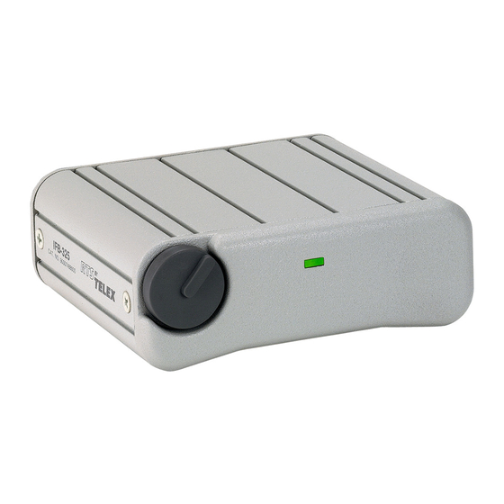
Description and Specifications General the IFB-325 is a portable user station for use with RTS 2-wire intercom systems. The IFB-325 is a listen-only IFB belt pack that can be used to listen to only one intercom channel. Features Features of the IFB-325 include: •... -
Page 6: Specifications
Introduction and Description Specifications General Channel Supplied Power Requirements 32 VDC nominal (standard RTS line), 50 to 80 mA Environmental Requirements Storage: -20°C to 80°C; 0% to 95% humidity, non-condensing Operating: 0°C to 50°C; 0% to 95% humidity, non-condensing Dimensions 3.25”... -
Page 7: Operation
Hole Plug: This hole is for future use. Intercom Channel Connectors: The IFB-325 intercom channel is connected via a 3-pin female connector. The IFB-325 is powered from the intercom system power supply and will turn ON with the intercom system. -
Page 8: Internal Jumper
Operation Internal Jumper The channel termination is set for operation on intercom channel two, which is compatible with other RTS equip- ment. If IFB operation is required on the intercom channel one, an internal jumper must be changed as described in Table 1. -
Page 9: Replacement Parts
Where to Obtain Parts Parts may be obtained directly from Telex at: Telex/RTS Systems 12000 Portland Avenue South Burnsville, MN 55337 Telephone: (800) 392-3497 Fax: (800) 323-0498 Mechanical Parts Final Assembly (Refer to Figure X for Item No. location Item No. - Page 10 Replacement Parts Circuit Board Assembly (Refer to Figure X) Ref No. Description Support Bracket C1, C2 Capacitor, CM, SM, 0.22μF, 50V Capacitor, CM, SM, 0.33μF, 50V Capacitor, CM, SM, 0.1μF, 50V Capacitor, EL, 2200μF, 16V Capacitor, EL, 100μF, 25V Capacitor, CM, SM, 0.01μF, 50V Capacitor, EL, 47μF, 25V Capacitor, CM, SM, 0.01μF, 50V Capacitor, EL, SM, 1μF, 50V...
-
Page 11: Diagrams
Drawing Number 9010-7488-000 9020-7477-001 9030-7477-001 9027-7477-001 Diagrams Title Figure X Final Assembly, IFB-325 Figure X Connector Plate Assembly, IFB-325 Figure X PC Board Assembly, IFB-325 Figure X Schematic, IFB-325 CHAPTER 4... - Page 12 Diagrams Final Assembly, IFB-325 FIGURE 3. 9010-7488-000, Rev F...
- Page 13 Connector Plate Assembly, IFB-325 FIGURE 4. 9020-7477-001, Rev E...
- Page 14 Diagrams PC Board Assembly, IFB-325 FIGURE 5. 9030-7477-001 Rev M...
Need help?
Do you have a question about the IFB-325 and is the answer not in the manual?
Questions and answers