RTS BP-325 User Manual
Belt-pack intercom station
Hide thumbs
Also See for BP-325:
- Specifications (2 pages) ,
- User manual (16 pages) ,
- User manual (24 pages)
Table of Contents
Advertisement
Advertisement
Table of Contents

Related Manuals for RTS BP-325


Summary of Contents for RTS BP-325
-
Page 1: User Manual
MODEL BP-325 Belt-pack Intercom Station User Manual 9350-5690-00 Rev. M 8/2008... - Page 2 Lincoln, NE 68507 U.S.A. Attn: Service USTOMER UPPORT Technical questions should be directed to: This package should include the following: Customer Service Department RTS/Telex Communications, Inc. Description Part No. 12000 Portland Avenue South Final Assy, BP325, Gray 9010673800 Burnsville, MN 55337 USA...
-
Page 3: Table Of Contents
General ................................ 5 Method One: One Channel Operation With A Non-rts Power Supply ............5 Line Input Connector Wiring For 1-channel Operation With Non-rts Power Supply ........ 6 Bottom View Of The Main Circuit Board ....................6 Line Loop Connector Wiring For 2-channel Operation With Non-rts Power Supply........ 6 Line Input Connector Wiring For 2-channel Operation With Non-rts Power Supply ........ -
Page 5: Chapter 1 - Connections And Operation
CONNECTIONS AND OPERATION This section describes operation of the BP325 as supplied from the factory. Use of an RTS power supply to power the intercom system is assumed. For options and use of an alternate power source (See “PROGRAMMABLE OPTIONS” on page 3. and See “ALTERNATE POWERING METHODS”... -
Page 6: Operation
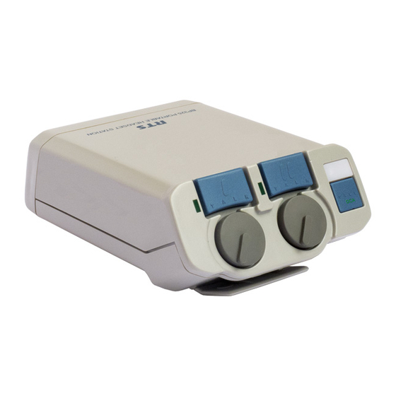
CONNECTIONS AND OPERATION Channel 1 talk button, indicator light and listen volume control. Channel 2 talk button, indicator light and listen volume control. Call button and indicator light. C A L L Carbon-mic headset jack. May also be used for external mic switch. See "Programable Options". Program volume control. -
Page 7: Programmable Options
STEREO PGM INPUT BP-325 Unit Jumper Settings - This equipment complies with the requirements in Part 15 of the FCC Rules for a TABLE 1. Class A computing device. Operation of this equipment in a residential area may cause unacceptable interference to radio... -
Page 8: Jumpers (W1-W7)
TALK button(s) OFF. Note, the TALK 3. Setup the left channel for program input. buttons may still be turned ON or OFF from the BP-325; however, the external mic switch will not work unless the TALK buttons are first turned ON at the BP-325... -
Page 9: Sidetone Adjustment
DC return. The unique design of RTS power supplies nel 1 TALK button. permits power to be carried on an audio channel. RTS power supplies also provide the proper terminating impedance for g. As supplied, the BP-325 can generate an inaudible each intercom channel. -
Page 10: Line Input Connector Wiring For 1-Channel Operation With Non-Rts Power Supply
Pin 3, Ch 2 +Audio Pin 2, Ch 1 +Audio TO BP325 LINE INPUT 200 Ohms 200 Ohms TO INTERCOM CHANNELS 10mF / 50V 10mF / 50V Pin 1, Common LINE INPUT Connector Wiring for 2-Channel Operation with Non-RTS Power Supply FIGURE 4. -
Page 11: Method Two: Two Channel Operation With A Non-Rts Power Supply
CONNECTIONS AND OPERATION METHOD TWO: TWO CHANNEL OPERATION WITH A NON-RTS POWER SUPPLY Referring to Figure 1, remove all three screws (10a and 10b) on the back connector panel of the BP325. Remove the rear cover/belt clip assembly. There are two connectors that connect the main circuit board to the front panel circuit board. - Page 12 CONNECTIONS AND OPERATION...
-
Page 13: Chapter 2 - Replacement Parts
CHAPTER 2 REPLACEMENT PARTS WHERE TO OBTAIN PARTS Parts may be obtained directly from RTS at: TELEX/RTS SYSTEMS Attn: Factory Service 8601 East Cornhusker Hwy. Lincoln, NE 68507 U.S.A. -
Page 14: Mechanical Parts
(Refer to Figure 3, “Rear Panel Assembly, BP325,” on page 19 drawing for Item No. locations) drawing for Item No. locations) Item Item No. Description RTS Part No. Description RTS Part No. Front/Top Panel Assy, 9020673700 Back Panel, Gray 9080563700... -
Page 15: Electrical Parts
REPLACEMENT PARTS ELECTRICAL PARTS C4,C5,C14,C36,C37,C107,C1 102879216 1000PF C2,C18,C19,C20,C25, 102879204 100PF ITEM QTY REF PART NUMBER VALUE C27,C28,C33,C39,C104 C12,C22,C23,C24,C26, C15,C21,C29,C102,C103,C10 1099R2263GT 22UF 102879271 10PF C30,C31,C32,C46 1502R2284E 2200UF C6,C7,C8,C11,C17,C44,C45, 53266124 C106,C108,C109,C111,C113, U13,U14 53281100 C114,CC1,CC2,CC3,CC4, 102880226 .1UF CC5,CC6,CC7,CC10,CC11, 53290000 CC12,CC13,CC14 J4,J5,J6,J7 59958103 59631000 102881339 .01UF J2,J3... - Page 16 REPLACEMENT PARTS...
-
Page 17: Chapter 3 - Specifications And Drawings
CHAPTER 3 Specifications and Drawings Specifications Program Input Maximum Input Level: +20 dBu Dimensions Nominal Input Level: -10 to +8 dBu 5.00” High x 3.75” Wide x 2.05” Deep Frequency Response: 100 Hz to 12 kHz, (127mm x 96.3mm x 52.1mm) +/-3 dB Weight Monaural Dynamic-mic Headset Connector... -
Page 18: Drawings
Specifications and Drawings Drawings Drawing Number Title 9030-6634-000 Front Panel Circuit Board Assemblyt 9030-6635-000 Main Board Layout 9020-6736-000 Rear Panel Assembly 9020-6737-000 Front/Top Panel Assembly 9010-6738-000 Final Assembly 9027-6635-000 Schematic Diagram, Main Circuit Board (pages 1 & 2) 2502-6736-000 Cable Assemblies... - Page 19 Figure 1: Front Panel Board Assembly, BP325...
- Page 20 Figure 2: Main Board, BP325...
-
Page 21: Front Panel Board Assembly, Bp325
Figure 3: Rear Panel Assembly, BP325... -
Page 22: Main Board, Bp325
Figure 4: Front/Top Panel Assembly, BP325... -
Page 23: Rear Panel Assembly, Bp325
Figure 5: Final Assembly, BP325... -
Page 24: Rear Panel Assembly, Bp325
Figure 6: Schematic, Main Board page 1... -
Page 25: Final Assembly, Bp325
Figure 7: Schematic, Main Circuit Board page 2... -
Page 26: Schematic Diagram, Front Panelcircuit Board
Figure 8: BP-325 Cable Assemblies...
Need help?
Do you have a question about the BP-325 and is the answer not in the manual?
Questions and answers