
Related Manuals for RTS Zeus III


Summary of Contents for RTS Zeus III
- Page 1 Zeus III Matrix Intercom User Manual Up to and including version 1.0.0 Rev. 05 OCTOBER/2015 F.01U.193.289...
- Page 2 SEE MARKING ON BOTTOM/BACK OF PRODUCT. site below: WARNING: APPARATUS SHALL NOT BE EXPOSED TO DRIPPING OR SPLASHING AND NO OBJECTS FILLED WITH LIQUIDS, SUCH AS RTS Intercoms ......www.rtsintercoms.com/warranty VASES, SHALL BE PLACED ON THE APPARATUS. RTS Digital RTSTW WARNING: THE MAIN POWER PLUG MUST REMAIN READILY OPER- ABLE.
-
Page 3: Important Safety Instructions
Zeus III Important Safety Instructions Read these instructions. Keep these instructions. Heed all warnings. Follow all instructions. Do not use this apparatus near water. Clean only with dry cloth. Do not block any ventilation openings. Install in accordance with the manufacturer’s instructions. - Page 4 Zeus III Bosch Security Systems, Inc. Rev. 05 F.01U.193.289 Technical Manual...
-
Page 5: Table Of Contents
Indicators and Controls ........................12 Connector Pinouts ..........................15 Dip Switches ............................18 2-Wire Settings in AZedit ........................22 Zeus III and GPIO-16 ........................... 24 Zeus and Accessory Dimensions ......................25 CABLES ............................. 27 Cable Requirements ..........................27 INSTALLATION ........................31 Requirements ............................ - Page 6 Zeus III CHANGING THE IP PROPERTIES ON YOUR PC .............. 57 UPL RESOURCE GUIDE ......................61 Notes ..............................69 Bosch Security Systems, Inc. Technical Manual F.01U.193.289 Rev. 05...
- Page 7 FIGURE 34. Audiocom (Balanced) Mode Configuration for Single Channel System ......42 FIGURE 35. ClearCom (Unbalanced) Mode Configuration ..............43 FIGURE 36. Keypanel Configuration ....................44 FIGURE 37. Trunking Configuration ....................44 FIGURE 38. Zeus III 4-Wire and 2-Wire Port Allocation ..............45 Bosch Security Systems, Inc. Technical Manual F.01U.193.289...
- Page 8 FIGURE 46. Open the Local Area Connection Status Window ............58 FIGURE 47. Open the Local Area Connection Properties Window ............. 59 FIGURE 48. Enter the IP Address of the Zeus III................. 60 FIGURE 49. Edit UPL Statement Window ................... 62 F.01U.193.289...
-
Page 9: Introduction
This system is excellent for smaller installations, as well as OB (Outside Broadcast) vans. Its compact size is perfect for small environments with limited space. With the addition of Ethernet, the Zeus III can be configured from virtually anywhere on the network using AZedit Intercom software. Alternatively, the Zeus III can be directly connected to AZedit through the use of the USB connector on the front panel. -
Page 10: Reference View
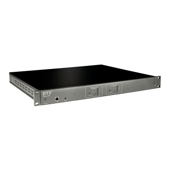
Status LED - 2-color status LED, for a more detailed description see “Status LEDs” on page 12. USB Connector Recessed Reset Button - Resets the Zeus III to its default configuration. Channel A Peak LED - If within the normal range of operation, the LED lights green, if the operating range is above the normal range the LED lights red. -
Page 11: Specifications
7.0lbs (3.18kg) 200Hz to 3.5kHz, ±4dB THD: NOTE: It is recommended to mount the Zeus III with a <1% at channel output with nominal input half inch (1/2”) spacing on the top and bottom of DATA PORTS the unit to allow for proper air flow. -
Page 12: Indicators And Controls
Status LEDs When the Zeus III powers on each time, the Status LED, located on the front panel (see Figure 2), cycle through a three (3) color sequence as it verifies the Zeus III is working properly. The LED color cycle starts with Red, goes to Orange, and ends with Green. - Page 13 The 2-Wire Mode Rotary Switch is used to select the 2-wire mode you want to configure your party line channel. Available options are: OFF - No modes are active RTS Channel 1 mode RTS Channel 2 mode Audiocom (Balanced) - Audiocom Mode ClearCom (Unbalanced) - ClearCom mode.
- Page 14 Zeus III Power 1 and Power 2 LED The Zeus III has two (2) power supplies powered by independent AC feeds. This allows for full power failover protection if one of the power supplies stops working. Green LEDs located on the front panel (see Figure 4) indicates whether the power supply is working properly or is broken.
-
Page 15: Connector Pinouts
Zeus III Introduction 15 Connector Pinouts Ethernet Connector Pin Out TABLE 4. USB Connector Pin Out TABLE 1. Ethernet Front USB RJ–45(Cat5) Standard Type B Function Function TX + V_BUS TX - RX + RX - Keypanel Port Connector Pin Out TABLE 2. - Page 16 TABLE 7. GPI Output #3 Party Line GPI Output #4 (2) 3-Pin Female XLR GPI Output #5 Audiocom Clear Com GPI Output #6 RTS CH1 RTS CH2 (Balanced) (Unbalanced) GPI Output #7 Function Function Function Function GPI Output #8 Common...
- Page 17 Zeus III Introduction 17 General Purpose Interface (GPI) Connector The GPI connector provides eight (8) general purpose control outputs. The control inputs can be assigned, using AZedit, to activate intercom ports, party lines, etc. The control outputs can also be assigned, using AZedit, to be activated by keypanel keys.
-
Page 18: Dip Switches
18 Introduction Zeus III Dip Switches To access the dip switches in the Zeus III unit, do the following: Using a Phillips head screwdriver, remove the four (4) top screws (see Figure 7). Screw locations on the Zeus III unit FIGURE 7. - Page 19 Zeus III Introduction 19 Dip Switch Locations FIGURE 8. Bosch Security Systems, Inc. Technical Manual F.01U.193.289 Rev. 05...
- Page 20 20 Introduction Zeus III S1 Dip Switch S1 Dip Switch FIGURE 9. Dip Switch S1 Reference TABLE 9. Dip Switch Description Default Setting Serial Baud Rate Set Off = 9600 baud On= 38.4k Authentication Not Required when using USB Connection...
- Page 21 Zeus III Introduction 21 S2 Dip Switch S2 Dip Switch FIGURE 10. S2 Dip Switch Reference TABLE 10. Dip Switch Description Default Setting Half duplex on 2-Wire Port 1 Off = disable half duplex mode on 2-wire port 1 On = enable half duplex mode on 2-wire port 1...
-
Page 22: 2-Wire Settings In Azedit
2-Wire Settings Group Box Use the 2-Wire Settings options to either use the currently set DIP switches, as set in the Zeus III or to override the DIP switch settings for the selected channel. You can set CH-A and CH-B independent from each other, if desired. - Page 23 Zeus III Introduction 23 To configure the 2-wire settings, do the following: From the System menu in AZedit, select Keypanel Assignment. The Keypanel / Ports window appears. Keypanel / Ports Window FIGURE 12. From the Alphas drop down list, select CH-A or CH-B.
-
Page 24: Zeus Iii And Gpio-16
NOTE: In the AZedit GPI Output window, Relays 1 – 8 are dedicated to Zeus III GPI Output. In the AZedit GPI Input window, GPI Inputs 1 – 8 are dedicated to Zeus III GPI Inputs.For more information on the GPIO-16, see the GPIO User Manual (9350-7842-000). -
Page 25: Zeus And Accessory Dimensions
Zeus III Introduction 25 Zeus and Accessory Dimensions Zeus and Accessory Dimensions FIGURE 13. NOTE: Front panel rack mounts fit industry standard 19” (483mm) racks and consoles. Dimensions exclude connectors. Allow at least 2 inches (51mm) for cables and connections. - Page 26 26 Introduction Zeus III Technical Manual Bosch Security Systems, Inc. F.01U.193.289 Rev. 05...
-
Page 27: Cables
Cables Each Zeus III intercom system has unique requirements for cables, so it is not practical to apply these with the unit. A USB interconnect cable has been provided, but even this may not be long enough for your system layout requirements. Most cables need to be custom built. - Page 28 28 Cables Zeus III Configuration Computer Cable FIGURE 16. IMPORTANT: Pins 2 and 3 are switched between the two (2) connectors. Connector Numbering FIGURE 14. Trunking Configuration Cable FIGURE 17. Cable Requirements FIGURE 15. GPIO-16 Interconnect Cable FIGURE 18. Technical Manual Bosch Security Systems, Inc.
- Page 29 Zeus III Cables 29 GPIO-16/PAP/LCP Interconnect Cable FIGURE 19. LCP Interconnect Cable FIGURE 20. RJ-45 Straight Cat-5 and RJ-45 Cat-5 FIGURE 21. Crossover Cable Bosch Security Systems, Inc. Technical Manual F.01U.193.289 Rev. 05...
- Page 30 30 Cables Zeus III Technical Manual Bosch Security Systems, Inc. F.01U.193.289 Rev. 05...
-
Page 31: Installation
Default Subnet Mask RVON-I/O 192.168.0.1 255.255.0.0 RVON-8 192.168.0.2 255.255.0.0 RVON-1 192.168.0.3 255.255.0.0 RVON-C 192.168.0.4 255.255.0.0 RVON-16 192.168.0.5 255.255.0.0 GPIO-16 192.168.0.6 255.255.0.0 MCII-e 192.168.0.7 255.255.0.0 Cronus 192.168.0.8 255.255.0.0 Zeus III 192.168.0.9 255.255.0.0 Technical Manual Bosch Security Systems, Inc. F.01U.193.289 Rev. 05... -
Page 32: Initial Power Up
The unit powers on. The Status LED, located on the front panel (see Figure 2 on page 12), cycles through a three (3) color sequence as it verifies the Zeus III is working properly. The LED color cycle starts with Red, goes to Orange, and ends with Green. -
Page 33: Zeus Iii Configuration
Ethernet • NOTE: You can only use one (1) type of communication configuration at a time. For example, if the Zeus III is connecting to AZedit via USB, it cannot also connect over Ethernet at the same time. Serial Configuration To configure the Zeus III for serial configuration, do the following: Attach a serial cable to the Trunk/To PC connector on the rear of the Zeus III. - Page 34 In AZedit, from the Options menu, select Communications. The Communications window appears. Serial Connection – Communications Window FIGURE 24. Select the Serial radio button. Click OK. The Zeus III is configured to connect to AZedit serially. Technical Manual Bosch Security Systems, Inc. F.01U.193.289 Rev. 05...
- Page 35 • extract the AZeditUSB32.exe file to C:\Telex\AZedit\USB on your computer • run the executable. To configure the Zeus III for USB configuration, do the following: Attach the supplied USB cable to the USB connector located on the front of the Zeus III. USB Connector FIGURE 25.
- Page 36 36 Installation Zeus III In AZedit, select Options|Communications. The Communications window appears. USB Connection – Communication Window FIGURE 26. Select the USB radio button. Click OK. The Zeus is configured to connect to AZedit via USB. Technical Manual Bosch Security Systems, Inc.
- Page 37 Straight Cat-5 Ethernet Connection FIGURE 27. Attach the other end of the Ethernet cable to the Ethernet connector located on the rear of the Zeus III. NOTE: By default, Zeus III is shipped with the IP Address 192.68.0.9 and the Network Mask 255.255.0.0.
- Page 38 From the Intercoms list field, select the Zeus III intercom you want to connect to. Click OK. The Available Intercoms window closes and the Communications window appears. Click OK. The Communications window closes. The Zeus III is configured for Ethernet operation via the supplied cable. Technical Manual Bosch Security Systems, Inc. F.01U.193.289...
- Page 39 To configure the Zeus III for Ethernet configuration using the CAT-5 crossover cable, do the following: By default, Zeus III is shipped with the IP Address 192.168.0.9 and the Network Mask 255.255.255.0. To change the IP Address, you must initially connect either serially or via USB. For crossover cable construction, see Figure 21 on page 29.
- Page 40 Initial IP Configuration of the Zeus III By default, the Zeus III is shipped with the IP Address 192.168.0.9 and the Net Mask 255.255.255.0. to change the IP Address initially, you must connect either serially or via USB. Connect to the PC with AZedit via a serial or USB cable.
-
Page 41: Typical System Installations
FIGURE 33. NOTE: CH A and CH B are not powered by the Zeus III, therefore a power supply must be used for party line channels. To configure a typical 2-wire channel A and B system, do the following: NOTE: A TW5W or TW7W breakout panel can be used to connect the 2-wire device, power supply and Zeus III unit. - Page 42 FIGURE 34. NOTE: CH A and CH B are not powered by the Zeus III, therefore a power supply must be used for party line channels. To configure a typical balanced mode system, do the following: NOTE: A TW5W or TW7W breakout panel can be used to connect the 2-wire device, power supply and Zeus III unit.
- Page 43 FIGURE 35. NOTE: CH A and CH B are not powered by the Zeus III, therefore a power supply must be used for party line channels. To configure a typical ClearCom (unbalanced) mode system, do the following: NOTE: A TW5W or TW7W breakout panel can be used to connect the 2-wire device, power supply and Zeus III unit.
- Page 44 To configure a trunking system, do the following: Connect a serial cable to the TRUNK/TO PC connector located on the rear panel of the Zeus III unit. Connect the other end of the serial cable to the serial cable connector located on the back of the MTM-2000.
-
Page 45: Party Line Introduction And Operation
Party Line Operation The Zeus III integrates 32 4-wire intercom ports (ports 1 – 32) with two (2) 2-wire intercom ports (ports 33 and 34), allowing audio to pass between the 2-wire channels and 4-wire channels. Any 2-wire system can be connected directly to the Zeus III without an SSA-324 or a DSI-2008, saving the space and expense of supporting two (2) units to convert the signal. - Page 46 Party Line Gain Adjustment with Zeus III Unlike the Zeus III 4-wire channels that can have their input and output gain adjusted, the 2-wire channels (Channel A and Channel B) can only have their input gains adjusted. This is because there is a limit on the amount of gain a 2-wire device can receive (see “Specifications”...
- Page 47 Call Signalling Zeus III party line channels (CH1 and CH2, see Figure 3 on page 13) support an integrated call signalling function controlled through the use of UPL statements in AZedit. Using a UPL statement, you can configure an indicator to activate when calls are received.
- Page 48 48 Party Line Introduction and Operation Zeus III Double-click a UPL Statement. The Edit UPL Statement window appears. Edit UPL Statement Window – AZedit FIGURE 41. In the comment field, enter an identifiable description for the UPL statement. Select the Enabled check box to enable the UPL statement.
- Page 49 Zeus III Party Line Introduction and Operation 49 From the drop down menu, select the channel the 2-wire system is connected to. Configure the Input Action FIGURE 43. In the Output Action Type drop down menu, select the output action you want to configure.
- Page 50 50 Party Line Introduction and Operation Zeus III When finished, click Done. The Edit UPL Statement window closes. The UPL Statement appears in the User Programmable Logic Statement window list. NOTE: Be sure to send your changes to the intercom system.
-
Page 51: Zeus Iii And Vox
CHAPTER 5 Zeus III and VOX The VOX window, shown in Figure 45, is used to configure Vox on ports in your intercom system. VOX is an audio threshold level you set at the point a channel becomes active. When the threshold is set, a channel does not activate until the preset audio level is attained. - Page 52 52 Zeus III and VOX Zeus III Threshold Group Box Adjust Box The Adjust box is used to fine tune the VOX threshold level, in dB, for the port after using the Set To slider. Use the adjustment arrows to increase or decrease the VOX threshold level in .5dB increments.
- Page 53 Zeus III Zeus III and VOX 53 Set To Button and Slider The Set To button and Slider is used to quickly get to the approximate hold time you want to set for the port. Once you have used the slider, click the Set To button to set the time for the port. Use the Adjust arrows to fine tune the hold time.
- Page 54 54 Zeus III and VOX Zeus III Threshold Column The Threshold column displays the audio level, in dB, at which vox activates on the port. Hold Time Column The Hold Time column displays the time, in seconds, the port waits for the presence of audio before turning off.
- Page 55 Zeus III Zeus III and VOX 55 Reset Hold Time Button The Reset Hold Time button is used to return the hold time for the selected port or ports to the default time. The default hold time is 0.5 seconds.
- Page 56 56 Zeus III and VOX Zeus III Technical Manual Bosch Security Systems, Inc. F.01U.193.289 Rev. 05...
-
Page 57: Changing The Ip Properties On Your Pc
APPENDIX A Changing the IP Properties on your PC IMPORTANT: Before you change any network settings on your computer, please make note of the current settings. NOTE: The following instructions are for Microsoft XP operating system and may differ slightly for other operating systems. - Page 58 Zeus III Select Properties. The Local Area Connection Status window appears. Open the Local Area Connection Status Window FIGURE 46. Technical Manual Bosch Security Systems, Inc. F.01U.193.289 Rev. 05...
- Page 59 Zeus III Click Properties. The Local Area Connection Properties window appears. Open the Local Area Connection Properties Window FIGURE 47. Select Internet Protocol (TCP/IP) from the connection list. Click Properties. The Internet Protocol (TCP/IP) Properties window appears. TIP: Remember to note the current settings.
- Page 60 Enter the IP Address of the Zeus III. FIGURE 48. In the IP address field, enter the IP Address you want to configure for the Zeus III, if desired. In the Subnet mask field, enter the Subnet Mask you want to configure the Zeus III, if desired.
-
Page 61: Upl Resource Guide
APPENDIX B UPL Resource Guide UPL (User Programmable Language) is a powerful feature which lets you quickly and easily program the intercom system to perform output actions you specify based on input conditions you specify. The UPL Statements window displays information concerning the UPL statements configured for your intercom system. - Page 62 Zeus III Edit UPL Statement Window FIGURE 49. UPL Statement Group Box Comment Field The Comment field is used to enter a description or comment about the current UPL statement. This field can contain up to 32 characters. Enabled Check Box The Enabled check box indicates the UPL statement is enabled and ready to use.
-
Page 63: Notes
Zeus III Input A Group Box Type and Variable Drop Down Menu The Type and Variable drop down menu is used to select an input condition that causes the intercom system to perform an output action. Each UPL statement can have either one (1) or two (2) input conditions. Depending on which is selected from the Type drop down menu, dictates what variable is needed. -
Page 64: F.01U.193.289 Rev
Zeus III Invert Input A Check Box The Invert Input A check box is used to reverse the input condition. For example, if the input condition is Talk Key, which by itself means, when a specified talk key is on, run the assigned output. - Page 65 Zeus III Input B Group Box Type and Variable Drop Down Menus The Type and Variable drop down menu is used to select an input condition that causes the intercom system to perform an output action. Each UPL statement can have either one (1) or two (2) input conditions. Depending on which is selected from the Type drop down menu.
- Page 66 Zeus III Invert Input B Check Box The Invert Input B check box is used to reverse the input condition. For example, if the input condition is “Talk Key”, which by itself means, when a specified talk key is on, run the assigned output.
- Page 67 Zeus III Output Values TABLE 14. Output Output Description Variables Needed THIS IS NOT CONFIGURABLE FROM AZEDIT. This option is used by command line protocol only. When a query is sent from the command line protocol to AZedit, a UPL Inform Command Line statement is written with “Inform Command Line Protocol”...
- Page 68 Zeus III Output Values TABLE 14. Output Output Description Variables Needed IFB Number, Alpha, Input Port Number, and Alpha Set the Program Input Port for an IFB Set IFB Program Input assignment. NOTE: If you set the Input Port Number to 0, you are assigning no input port.
-
Page 69: Bosch Security Systems, Inc. Technical Manual F.01U.193.289 Rev
Zeus III Notes Bosch Security Systems, Inc. Technical Manual F.01U.193.289 Rev. 05... - Page 70 Bosch Security Systems, Inc. 12000 Portland Avenue South Burnsville, MN 55337 U.S.A. www.boschcommunications.com...
Need help?
Do you have a question about the Zeus III and is the answer not in the manual?
Questions and answers