Table of Contents
Advertisement
Quick Links
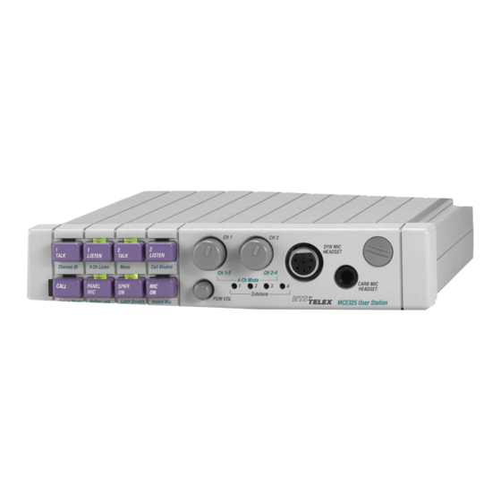
The MCE-325 is a four-channel, programmable intercom station. It may be used as a headset station or, with the addition of
the MCS-325 Modular Speaker, as a speaker station. It may be mounted in a console or equipment rack via optional mounting
kits. The MCE-325 can be used with either two-wire or four-wire intercom lines, or a combination of both. In the labeling on the
MCE-325, references to channels 1, 2, 3, and 4 indicate two-wire lines; references to four-wire A and four-wire B indicate four-
wire lines. The MCE-325 can be interfaced to a variety of external devices including external program sources, two-way radios,
paging systems, and satellite circuits.
Features
Call Signaling
Call signaling is accomplished using an inaudible (20 kHz)
signal to activate a call indicator LED.
Remote "talk-off"
Active, unattended remote station microphones may be
deactivated by momentarily injecting an inaudible (24 kHz)
signal into the corresponding intercom line. The MCE-325
can send and receive "talk-off" signals.
VOX circuit
The MCE-325 may be programmed for voice activation of
the microphone.
Simple IFB
Program audio assigned to a channel is interrupted during
talk.
Line Drawing
MCE-325
User Station
External device keying
External devices, such as two-way radios, speaker mute
relays, or paging systems may be activated through key
outputs at the auxiliary connector on the rear panel. The key
outputs may also be used to expand the simple IFB function,
allowing any one of a number of MCE-325 stations to inter-
rupt the program source and talk on the line.
Microphone Limiter
The microphone preamplifier circuit contains a limiter, which
helps to equalize voice levels.
Fully programmable
Retains programming even when power is shut off.
Instantaneous Auto-Reset
Instantaneous Auto Reset (IAR), the newest technology in
performance and safety, which uses a revolutionary new
circuitry that dynamically monitors line fault conditions. Then,
when the fault is removed, automatically brings individual
power supply channels up.
Advertisement
Chapters
Table of Contents

Related Manuals for RTS MCS-325


Summary of Contents for RTS MCS-325
- Page 1 The MCE-325 is a four-channel, programmable intercom station. It may be used as a headset station or, with the addition of the MCS-325 Modular Speaker, as a speaker station. It may be mounted in a console or equipment rack via optional mounting kits.
- Page 2 MCE-325 Specifications General Bridging Impedance (to line) 10,000 Ω typical Noise Contribution to 200-Ω Line -90 dBu Call Signal Frequency 20 kHz, crystal controlled Talk-off Frequency 24 kHz, crystal controlled Microphone Preamplifier Maximum Voltage Gain 54 dB Frequency Response 100 Hz to 8,000 Hz, ±3 dB Input Impedance 1,000 Ω...
- Page 3 NSTRUCTIONS MCE325 ODEL ROGRAMMABLE TATION 9350-6464-00 Rev L, 11/2006...
- Page 4 See the enclosed warranty card for further details. Attn: Service USTOMER UPPORT This package should include the following: Technical questions should be directed to: Customer Service Department RTS/Telex Communications, Inc. 12000 Portland Avenue South Burnsville, MN 55337 USA Telephone: 800-392-3497 Fax: 800-323-0498 ETURN HIPPING...
-
Page 5: Table Of Contents
ABLE OF ONTENTS Description & Specifications Description ............1-1 General . - Page 6 Unswitched Microphone Output ......... . . 2-11 External DC Power Source .
- Page 7 IFB A ............4-9 Level and Frequency Response Check, Four-Wire Input to Headphone .
-
Page 9: Description & Specifications
E C T I O N & S ESCRIPTION PECIFICATIONS HAPTER Description General The MCE325 is a four-channel, programmable intercom station. It may be used as a headset station or, with the addition of the MCS325 Modular Speaker, as a speaker station. It may be mounted in a console or equipment rack via optional mounting kits. -
Page 10: Front Panel Features
The panel microphone jack accepts specially made gooseneck microphones (MCP-90 series), which are available from RTS. M C E 3 2 5 U s e r I n s t r u c t i o n s... -
Page 11: Rear Panel Features
MCE325 front and rear panel features. Figure 1.1 Volume Dynamic-Mic Panel Channel Selector Controls Headset Connector Jack Operation Buttons CH 1 CH 2 LISTEN LISTEN TALK TALK Channel ID 4-Ch Listen Mono Call Disable SPKR CALL PANEL Setup Mode Button Lock Latch Disable Instant Mic Sidetone Nulling Trimmers Program... -
Page 12: Speaker Output
be assigned to a four-wire channel. The program assigned to channels is interrupted during talk output. Speaker Output A ¼-inch phone jack is provided for connection of an external speaker (8-ohms minimum impedance). The speaker output is compatible with the MCS325 speaker. Auxiliary Connector Standard Options on the 25-pin, female, D-Sub connector are: Unswitched microphone output... -
Page 13: Mce325 Specifications
MCE325 Specifications General Bridging Impedance (to line) 10,000 ohms typical Noise Contribution to 200-ohm Line -90 dBu Call Signal Frequency 20 kHz, crystal controlled Talk-off Frequency 24 kHz, crystal controlled Microphone Preamplifier Maximum Voltage Gain 54 dB Frequency Response 100 Hz to 8,000 Hz, ±3 dB Input Impedance 1,000 ohms Limiter Range... -
Page 14: Connectors
Connectors Intercom Line Connector XLR type, 3-pin (male-female loop through on two-wire channel 1 and 2, or four-wire channel A; Female only on two-wire channel 3 and 4, or four-wire channel B Dynamic Mic XLR type, 6-pin female Carbon Mic ¼-inch phone jack, 3-circuit Auxiliary Connector 25-pin, female, D-Sub... - Page 15 Standard four-channel, two-wire configuration. Figure 1.3 A four-channel, two-wire configuration with two channels used for IFB’s. Figure 1.4 Figure 1.5 Configuration for one or two two-wire channels and one four-wire channel.
- Page 16 Standard two-channel, four wire configuration. Figure 1.6 Figure 1.7 Multiple interconnected stations in four-channel, two-wire configuration with two channels used for IFB’s. M C E 3 2 5 U s e r I n s t r u c t i o n s...
- Page 17 Multiple interconnected stations using one four-wire intercom channel and two two-wire Figure 1.8 channels for IFB’s. Figure 1.9 A four-channel, two-wire configuration with two channels used for IFB’s (shown with TELCO interface).
- Page 18 Configuration for an ENG truck using one four-wire intercom channel and two two-wire Figure 1.10 IFB’s. 1-10 M C E 3 2 5 U s e r I n s t r u c t i o n s...
- Page 19 Figure 1.11 MCE325 button configurations. 1-11...
- Page 20 1-12 M C E 3 2 5 U s e r I n s t r u c t i o n s...
-
Page 21: Installation
E C T I O N NSTALLATION HAPTER Internal Programming and Adjustments WARNING Hazardous voltages exist inside this equipment. Disconnect the AC line cord before opening the equipment or attempting any internal programming or adjusting. General Prior to installing the MCE325, it may be necessary to change some of the internal programming to suit your particular application. -
Page 22: Intercom Line-Channel Configurations (Ds1-Ds3, J6, J7, J19 & J20)
Top cover removal. Figure 2.1 Intercom Line-Channel Configurations (DS1-DS3, J6, J7, J19 & J20) The four channels of the MCE325 may be assigned to intercom lines in a variety of ways. Channel assignment is determined by the settings of DIP switches DS1 through DS3 and jumpers J6, J7, J19, and J20. - Page 23 When a two-wire line is connected to channel one and a four-wire line is connected to channel For all other intercom line configurations that use two-wire lines, DS3 must be set to the “on” position for four-channel operation. Jumper functions and default settings. Table 2.2 Jumper Number Jumper Function Default Setting...
- Page 24 Internal DIP switches, jumpers and level trimmers. Figure 2.2 M C E - 3 2 5 U s e r I n s t r u c t i o n s...
-
Page 25: Front Panel Setup Mode Lock-Out (Ds4)
Section 3, Operation. ISO (DS5) The MCE325 may be used with an RTS Model VCP6A, VCP12A, or VCP12B Control Station to permit private conversation between the MCE325 operator and a camera operator. When ISO mode is engaged, either talk, or talk and listen (depending on the setting of DS5) for all other channels connected to the MCE325 will be muted, and a private line will be established between the MCE325 operator and the camera operator. -
Page 26: Program Assignment - Ifb Option (J4, J5, J16-J18)
Program Assignment – IFB Option (J4, J5, J16-J18) Jumper J4 assigns PROGRAM A to two-wire CH 3 or four-wire CH B with interrupt during talk (IFB A). Jumper J5 assigns PROGRAM B to CH 4 with interrupt during talk (IFB B). (PROGRAM B is not used in four-wire mode.) Jumpers J16, J17, and J18 assign the mono mix of both program inputs to the left headphone, right headphone, and speaker respectively. - Page 27 Mounting configurations. Figure 2.3...
-
Page 28: Electrical Installation
Electrical Installation AC Power and Fuse The Model MCE325 is pre-wired for either 115 or 230 VAC operation, and the appropriate fuse is already installed. The MCE325 uses a 0.5A Slo-Blo fuse for 115 volt operation, or a 0.25A Slo- Blo fuse for 230 volt operation. -
Page 29: Program Inputs, J14 And J15
resistor values. These resistors would normally be installed in the cable connector, but may be placed at any point in the signal path. Recommended values are shown in Figure 2-4. Program Inputs, J14 and J15 The PROGRAM A and B inputs accept line-level (0 dBu nominal), balanced audio. The program inputs are connected using ¼-inch stereo phone plugs. -
Page 30: Key Outputs - Expanded Ifb Option
ISO Connection To connect an RTS Model VCP6A, VCP12A, or VCP12B ISO Control Panel to the MCE325, connect the unswitched microphone output of the MCE325 (pins 1 and 14 of the auxiliary connector) to the four-wire input of the VCP Control Panel;... -
Page 31: External Electret Microphone
Separate shielded twisted pair cables: 50 feet (15.24 m). Balanced microphone input: up to 100 feet (30.48 m). External Electret Microphone An external electret microphone may be connected at the auxiliary connector and used in place of a front-panel gooseneck microphone. Connect microphone high/bias to pin 15 and connect microphone low to pin 2. - Page 32 Carbon-microphone headset connector: ¼-inch, tip-ring-sleeve phone jack. Carbon-microphone headset connector. Table 2.9 SECTION FUNCTION Carbon microphone Ring Headphone Sleeve Common/ground 2-12 M C E - 3 2 5 U s e r I n s t r u c t i o n s...
-
Page 33: Operation
E C T I O N PERATION HAPTER General The front panel buttons have different functions when the MCE325 is switched from operating mode to setup mode. Legends on the buttons indicate their operating mode functions; legends under the buttons indicate their setup mode functions. All of the front panel buttons were pre- programmed for a certain type of operation. -
Page 34: Panel Mic/Headset Mic Selection
button action can be changed, via the front panel programming, so that the button controls talk only, with listen either always on or always off. Panel Mic/Headset Mic Selection The PANEL MIC button selects either panel microphone (LED on) or headset microphone (LED off). -
Page 35: Sending And Receiving Call Signals
turned on to prevent feedback. See “Headphone Sidetone Trimmer Adjustment (R37)” for further details. Sending and Receiving Call Signals To call a channel: Press the CALL button; the CALL LED’s will flash to indicate “call signal ready”. Press and hold the talk button for the channel to be called; the call signal will be transmitted as long as the talk button is held. -
Page 36: Channel Id
Channel ID The MCE325 can be programmed so that when someone is talking on an intercom channel, the corresponding listen button LED will flicker as they talk to provide a visual indication of which channel is talking. With the Channel ID submenu selected, press each TALK button to select or deselect Channel ID. -
Page 37: Instant Mic
Long LED blink (90% on, 10% off): Latching disabled. Instant Mic Talk buttons may be individually programmed to automatically activate the microphone when pressed. With the Instant Mic submenu selected, press each talk button one or more times to select the desired type of operation as follows: Short LED blink (50% on, 50% off): Instant mic off (default). - Page 38 M C E - 3 2 5 U s e r I n s t r u c t i o n s...
-
Page 39: Maintenance
E C T I O N AINTENANCE HAPTER Preventive Maintenance Clean the unit and verify its performance periodically. Factory Support Information Factory support information is located on the first page of this manual. Corrective Maintenance WARNING: Hazardous voltages exist inside the MCE325. Attempting diagnosis, repair, or adjustment with the AC line connected could result in serious injury or death. -
Page 40: Cleaning
The ribbon connector from the front panel board to the main board is attached at both ends with locking connectors. To unlock the connector, pull the outer shell away from the circuit board. Then, pull the ribbon cable out. Cleaning Clean the front panel and case with alcohol or a mild solution of detergent and water, and then wipe off detergent residue with a damp rag. -
Page 41: Initial Configuration
Measure the ripple. = 140 mVp-p ripple Measure the regulated DC voltage at U26 pin 2. (There should be no ripple.) = 13.85 ±0.3 VDC U26-2 Measure the mid-voltage source at U17 pin 7. = 6.93 ±0.3 VDC U17-7 Measure the +5 V source at the output of U27 pin 2. = 5.0 ±0.3 VDC U27-2 Initial Configuration... -
Page 42: Usmb (Un-Switched Microphone Balanced) Frequency Response And Level Check
Set the MIC ON button to on. Set all other front panel buttons to off. Check for 13 VDC minimum at the key 1 output. Turn CH 1 TALK on and check for less than 2 VDC at the key 1 output. Repeat steps 3 and 4 for the other channels: CH2 TALK: key 2 out (J22 pin 19) CH3 TALK: key 3 out (J22 pin 7) -
Page 43: Two-Channel, Four-Wire Mode
USMB frequency response and level check. Table 4.2 10 kHz -55 dBu (1.4 mV) -5.7 ±3 dBu (0.28 – 0.57 VAC) –45 dBu (4.35 mV) 2.2 ±2 dBu (0.79 – 1.26 VAC) –25 dBu (43.5 mV) 2.5 ±2dBu (0.83 – 1.32 VAC) Table 4.3 Mic to line response;... -
Page 44: True Sidetone Adjust
Repeat for channels 2 through 4 by activating the TALK buttons, connecting to the test points and adjusting the potentiometers as indicated in Table 4.4. True Sidetone Adjust Configure the DYN MIC HEADSET jack for stereo mode (See Section 3, “MONO”) Set all front panel buttons to off. -
Page 45: Level And Frequency Response Check, Intercom Channel To Speaker
Level and Frequency Response Check, Intercom Channel to Speaker Set all front panel buttons to off. Set all volume controls to minimum. Connect an 8 ohm load across the speaker output (J27, tip and ring) Connect an AC voltmeter and an oscilloscope across the speaker output. Connect the signal generator to intercom channel 1, and adjust the generator output to –1 dBu, 1 kHz. -
Page 46: Program B To Right Headphone
Restore jumper J16 to short pins 1 & 2. Program B to Right Headphone Remove the signal from the PROGRAM A input, and connect it to the PROGRAM B input. Measure the level at the right headphone output (J2, 3 & 5). It should be 1.3 dBu ±2 dBu. (Program volume at maximum.) Set the signal generator to 0 dBu, 100 Hz. -
Page 47: Ifb A
IFB A Move the J4 jumper to short pins 1 and 2 (IFB A assigned to channel 3). Remove the signal from PROGRAM B input, and connect it to the PROGRAM A input. Set the signal generator to 0 dBu, 1 kHz. Check the output level across intercom channel 3. -
Page 48: Panel Mic To Channel Test
Panel Mic to Channel Test Turn all front panel buttons off. Set all volume controls to minimum. Remove the signal from the Four-Wire B input and reconnect it to the panel mic input (J28 tip and ring, it is easiest to connect to the back of the connector.). Set the signal generator to –25 dBu, 1 kHz. -
Page 49: Mic Kill Transmit Test
Try turning the MIC ON button on. It should not stay on. Adjust signal generator to –5 dBu at 25.680 kHz. Try turning the MIC ON button on and off. It should turn on and off as usual. Adjust signal generator to –5 dBu at 24.480 kHz. Try turning the MIC ON button on. -
Page 50: Iso Test
ISO Test Set DIP switch DS3 to off (two-channel, two-wire mode). Set DIP switch DS5 to on (talk muted during ISO). Set all TALK and LISTEN buttons to on. Connect a 100 ohm resistor from the ISO input (J22 pin 12) to circuit common (J22 pin 10). Observe that the MIC ON LED turns on and the channel 1 and 2 TALK buttons turn off. - Page 51 Turn on the SPKR ON button. The meter should read –38 dBu or less. Turn off the SPKR ON button. Noise measurements in the following steps were made using a 400 Hz to 30 kHz bandpass NOTE filter with +40 dB of gain. Turn on the MIC ON switch.
- Page 52 4-14 M C E - 3 2 5 U s e r I n s t r u c t i o n s...
-
Page 53: Parts Lists
E C T I O N ARTS ISTS HAPTER Packaging Assembly (9000-6464-00) Reference PD6464 Drawing, Section 6 Table 5.1 Item No. Description RTS Part No. User Manual, MCE325 User Station 9350-6464-00 Label, Warning 9170-6739-00 Final Assy, MCE325 9010-6464-00 Assy, 200-ohm Termination Plug 9020-6793-00... -
Page 54: Front Panel Assembly (9020-6261-00)
Front Panel Assembly (9020-6261-00) Reference AS6261 Drawing, Section 6 Table 5.3 Item No. Description RTS Part No. Bezel, MCE325 9070-6261-00 PC Board Assy, Front Panel, MCE325 9030-6246-00 Bushing Adapter 9110-6273-00 Keycap Stem 4501-0064-00 Knob, Channel Volume, MCE325 2703-0033-00 Knob, Program Volume, MCE325... -
Page 55: Back Panel Assembly (9020-6262-00)
Back Panel Assembly (9020-6262-00) Reference AS6262 Drawing, Section 6 Table 5.4 Item No. Description RTS Part No. PC Board Assy, Main 9030-6245-00 Heatsink Assy 9020-6324-00 Panel, Rear 9080-6262-00 Jack, Phone, 3 conductor, double closed circuit (J27) 2013-0003-00 Connector Housing (P23) - Page 56 Reference 9027-6245-01 Drawing, Section 6 Table 5.6 C104 Capacitor, CM, 0.1µF, 50V 52676113 C105 Capacitor, EL, 100µF, 25V 51821524 C106 Capacitor, EL, 4.7µf, 25V 51821621 C107 Capacitor, EL, 4.7µf, 25V 51821622 C108 Capacitor, EL, 100µF, 25V 51821524 C109 Capacitor, EL, 1000µF, 25V 51821526 Capacitor, CM, 0.1µF, 50V 52676113...
- Page 57 Reference 9027-6245-01 Drawing, Section 6 Table 5.6 Capacitor, EL, 10µF, 50V 51821110 Capacitor, CD, 100pF, 100V 1501R1011L Capacitor, CD, 100pF, 100V 1501R1011L Capacitor, CM, 0.1µF, 50V 52676113 Capacitor, CD, 10pF, 500V 52157502 Capacitor, CM, 0.1µF, 50V 52676113 Capacitor, EL, 22µF, 50V 51821640 Capacitor, EL, 47µF, 16V 51821068...
- Page 58 Reference 9027-6245-01 Drawing, Section 6 Table 5.6 Capacitor, Mylar, 1nF, 100V 1514R1022L Capacitor, EL, 10µF, 50V 51821110 Capacitor, CD, 100pF, 100V 1501R1011L Capacitor, Mylar, 1nF, 100V 1514R1022L Capacitor, CM, 0.1µF, 50V 52676113 Capacitor, EL, 10µF, 50V 51821110 Capacitor, Mylar, 1nF, 100V 1514R1022L Capacitor, EL, 10µF, 50V 51821110...
- Page 59 Reference 9027-6245-01 Drawing, Section 6 Table 5.6 Diode, 1N4004 50745005T Diode, 1N4004 50745005T Diode, 1N4004 50745005T Diode, 1N914B 160109140B Diode, 1N914B 160109140B Diode, 1N914B 160109140B Diode, 1N914B 160109140B Diode, 1N4004 50745005T Diode, 1N4004 50745005T Diode, 1N4004 50745005T Diode, 1N914B 160109140B Diode, 1N914B 160109140B Diode, 1N914B...
- Page 60 Reference 9027-6245-01 Drawing, Section 6 Table 5.6 Transistor, 2N5210 1602521000 Transistor, 2N5210 1602521000 Resistor, CF, 1K Ohm, 5%, 1/8W 52154060 Resistor, MF, 3.01K Ohm, 1%, 1/8W 54034301 R100 Resistor, CF, 22K Ohm, 5%, 1/8W 524154028 R101 Resistor, CF, 10K Ohm, 5%, 1/8W 52154036 R104 Trimpot, 10K Ohm, Linear...
- Page 61 Reference 9027-6245-01 Drawing, Section 6 Table 5.6 R170 Resistor, CF, 10K Ohm, 5%, 1/8W 52154036 R171 Resistor, CF, 10K Ohm, 5%, 1/8W 52154036 R172 Resistor, MF, 201 Ohm, 1%, 1/8W 54032301 R173 Resistor, CF, 100K Ohm, 5% 1/8W 52154012 R174 Resistor, MF, 201 Ohm, 1%, 1/8W 54032301 R175...
- Page 62 Reference 9027-6245-01 Drawing, Section 6 Table 5.6 R267 Resistor, MF, 201 Ohm, 1%, 1/8W 54032301 R268 Resistor, CF, 200 Ohm, 5%, 1/8W 52154077 R269 Resistor, CF, 10K Ohm, 5%, 1/8W 52154036 Resistor, CF, 200 Ohm, 5%, 1/8W 52154077 Resistor, CF, 22K Ohm, 5%, 1/8W 52154010 Resistor, CF, 5.1M Ohm, 5%, 1/8W 52154698...
- Page 63 Reference 9027-6245-01 Drawing, Section 6 Table 5.6 Resistor, CF, 22K Ohm, 5%, 1/8W 524154028 Resistor, CF, 22K Ohm, 5%, 1/8W 524154028 Resistor, CF, 22K Ohm, 5%, 1/8W 524154028 Resistor, MF, 301 Ohm, 1%, 1/8W 54034150 Resistor, CF, 10K Ohm, 5%, 1/8W 52154036 Trimpot, 10K Ohm, Linear 1409006000...
- Page 64 Reference 9027-6245-01 Drawing, Section 6 Table 5.6 IC, Dual Low-noise Op-Amp, NE5532N 53295000 IC, Dual Low-noise Op-Amp, NE5532N 53295000 IC, Dual Low-noise Op-Amp, TLO76 1603013500 IC, Dual Low-noise Op-Amp, TLO77 1603013500 IC, Analog Switch, CD4053BE 46638P1 IC, Analog Switch, CD4053BE 46638P1 IC, Analog Switch, CD4053BE 46638P1...
-
Page 65: Pc Board Assembly, Front Panel (9030-6246-00)
PC Board Assembly, Front Panel (9030-6246-00) Reference AS6246 Drawing, Section 6 Table 5.7 Ref No. Description RTS Part No. R1-R3 Pot, 10K Ohm, Audio 1406003901 LED, Super Bright, Red 1801001900 DS1-DS8 LED, Super Bright, Yellow 1801002200 S1-S8 Keyswitch, No LED... - Page 66 5-14 M C E - 3 2 5 U s e r I n s t r u c t i o n s...
-
Page 67: Diagrams
E C T I O N IAGRAMS HAPTER... - Page 76 12000 Portland Avenue South • Burnsville, MN • 55377...
- Page 77 NSTRUCTIONS MCE-325 ODEL ROGRAMMABLE TATION Rev. 13 NOVEMBER/2013 F.01U.193.228...
- Page 78 WARNING: APPARATUS SHALL NOT BE EXPOSED TO DRIPPING OR site below: SPLASHING AND NO OBJECTS FILLED WITH LIQUIDS, SUCH AS VASES, SHALL BE PLACED ON THE APPARATUS. RTS Intercoms ......www.rtsintercoms.com/warranty WARNING: THE MAIN POWER PLUG MUST REMAIN READILY OPERABLE. RTS Digital RTSTW...
- Page 79 MCE-325 Programmable User Station Important Safety Instructions Read these instructions. Keep these instructions. Heed all warnings. Follow all instructions. Do not use this apparatus near water. Clean only with dry cloth. Do not block any ventilation openings. Install in accordance with the manufacturer’s instructions.
- Page 80 MCE-325 Programmable User Station Bosch Security Systems, Inc. Rev. 13 F.01U.193.228 Technical Manual...
- Page 81 Table Contents DESCRIPTION & SPECIFICATIONS ..................7 Description ...............................7 General ................................. 7 Features ................................7 Front Panel Features ..........................8 Channel Selector and Operation Buttons ......................8 Volume Controls ..............................8 Sidetone Nulling Trimmers ..........................8 Connections, Inputs and Outputs ......................9 Front Panel ................................
- Page 82 MCE-325 Programmable User Station Mechanical Installation ..........................25 Electrical Installation ..........................27 AC Power and Fuse ............................27 Intercom Lines J8, J9, J10 ..........................27 General ................................27 Connector Pin Outs ............................27 4-wire Termination ............................28 Program Inputs, J14 and J15 .......................... 28 External Speaker, J27 .............................
-
Page 83: Description & Specifications
CHAPTER 1 Description & Specifications Description General The MCE-325 is a 4-channel, programmable intercom station. It may be used as a headset station or, with the addition of the MCS325 Modular Speaker, as a speaker station. It may be mounted in a console or equipment rack via optional mounting kits. The MCE-325 can be used with either 2-wire or 4-wire intercom lines, or a combination of both. -
Page 84: Front Panel Features
8 Description & Specifications MCE-325 Programmable User Station Front Panel Features Channel Selector and Operation Buttons These buttons have two (2) modes of operation: standard operating mode and setup mode. The printing on the face of each button indicates its function in standard operating mode; printing under each button indicates its setup mode function. (For operation and programming instructions, see “Operation”... -
Page 85: Connections, Inputs And Outputs
The MCE-325 may be optionally fitted with a gooseneck panel microphone by removing the blanking plug located in the upper-right corner of the front panel. The panel microphone jack accepts specially made gooseneck microphones (MCP-90 series), which are available from RTS. MCE-325 front and rear panel features FIGURE 1. -
Page 86: Rear Panel Features
10 Description & Specifications MCE-325 Programmable User Station Rear Panel Features Intercom Lines Connectors J8 and J9 are parallel-wired for loop-through connection to additional stations. These connectors are used either for 2-wire CH 1 and CH 2 input/output, or 4-wire CH A output. (The 4-wire CH A input is connected at the auxiliary connector.) Connector J10 is used for 2-wire CH 3 and CH 4 input/output, or 4-wire CH B output, but no loop-through connector is provided for these channels. -
Page 87: Programming
MCE-325 Programmable User Station Description & Specifications 11 Programming Three (3) methods of programming are used: Front panel programming via the channel selector and operation buttons. Internal programming via circuit board DIP switches. Internal programming via circuit board jumpers. The most commonly programmed options are assigned to the front panel for convenience. Detailed information on internal programming is provided in “Installation”... -
Page 88: Mce-325 Specifications
12 Description & Specifications MCE-325 Programmable User Station MCE-325 Specifications General Bridging Impedance (to line) ..........................10,000Ω typical Noise Contribution to 200 Ω Line............................-90dBu Call Signal Frequency ..........................20kHz, crystal controlled Talk-off Frequency ..........................24kHz, crystal controlled Microphone Preamplifier Maximum Voltage Gain ................................. 54dB Frequency Response.......................... -
Page 89: Mcs325 Specifications
MCE-325 Programmable User Station Description & Specifications 13 MCS325 Specifications The MCS325 is designed for use with MCE-325, but may also be used as a general-purpose monitor for program material. Impedance ..............................8Ω (DCR5.5 to 7Ω) Power Rating..............................5W RMS continuous Sensitivity...................90dB ±2dB/2.83volts/one (1) meter on axis averaged over one (1) octave bands centered at 250Hz, 500Hz, 1kHz, 2kHz, 4kHz, and 8kHz when enclosed in a sealed box... - Page 90 14 Description & Specifications MCE-325 Programmable User Station A 4-channel, 2-wire configuration with two (2) channels used for IFB’s FIGURE 4. Configuration for one (1) or two (2) 2-wire channels and one (1) 4-wire channel FIGURE 5. Standard 2-channel, 4-wire configuration FIGURE 6.
- Page 91 MCE-325 Programmable User Station Description & Specifications 15 Multiple interconnected stations in 4-channel, 2-wire configuration with two (2) channels used for IFB’s FIGURE 7. Multiple interconnected stations using one (1) 4-wire intercom channel and two (2) 2-wire channels for IFB’s FIGURE 8.
- Page 92 16 Description & Specifications MCE-325 Programmable User Station A 4-channel, 2-wire configuration with two (2) channels used for IFB’s (shown with TELCO interface) FIGURE 9. Configuration for an ENG truck using one (1) 4-wire intercom channel and two (2) 2-wire IFB’s FIGURE 10.
- Page 93 MCE-325 Programmable User Station Description & Specifications 17 MCE-325 button configurations FIGURE 11. Bosch Security Systems, Inc. Technical Manual F.01U.193.228 Rev. 13...
- Page 94 18 Description & Specifications MCE-325 Programmable User Station Technical Manual Bosch Security Systems, Inc. F.01U.193.228 Rev. 13...
-
Page 95: Installation
CHAPTER 2 Installation Internal Programming and Adjustments CAUTION: These servicing instructions are for use by qualified service personnel only. To reduce the risk of electrical shock do not perform any servicing other than what is included in the operating instructions, unless you are qualified to do so. - Page 96 20 Installation MCE-325 Programmable User Station Top cover removal FIGURE 12. Technical Manual Bosch Security Systems, Inc. F.01U.193.228 Rev. 13...
-
Page 97: Intercom Line Channel Configurations (Ds1-Ds3, J6, J7, J19, And J20)
MCE-325 Programmable User Station Installation 21 Intercom Line Channel Configurations (DS1-DS3, J6, J7, J19, and J20) The four (4) channels of the MCE-325 may be assigned to intercom lines in a variety of ways. Channel assignment is determined by the settings of DIP switches DS1 through DS3 and jumpers J6, J7, J19, and J20. There are six (6) possible intercom line configurations. - Page 98 22 Installation MCE-325 Programmable User Station Jumper Functions and Default Settings TABLE 2. Jumper Default Jumper Function Number Setting Assigns PROGRAM A input to 2-wire CH 3 or 4-wire CH B Not Assigned Not assigned: pins 2 & 3 shorted Assigned: pins 1 &...
- Page 99 MCE-325 Programmable User Station Installation 23 Internal DIP switches, jumpers, and level trimmers FIGURE 13. Bosch Security Systems, Inc. Technical Manual F.01U.193.228 Rev. 13...
-
Page 100: Front Panel Setup Mode Lock-Out (Ds4)
ISO (DS5) The MCE-325 may be used with an RTS Model VCP-6A, VCP-12A, or VCP-12B Control Station to permit private conversation between the MCE-325 operator and a camera operator. When ISO mode is engaged, either talk, or talk and listen (depending on the setting of DS5) for all other channels connected to the MCE-325 is muted, and a private line is established between the MCE-325 operator and the camera operator. -
Page 101: Program Assistant - Ifb Option (J4, J5, J16-J18)
MCE-325 Programmable User Station Installation 25 Program Assistant – IFB Option (J4, J5, J16-J18) Jumper J4 assigns PROGRAM A to 2-wire CH 3 or 4-wire CH B with interrupt during talk (IFB A). Jumper J5 assigns PROGRAM B to CH 4 with interrupt during talk (IFB B). (PROGRAM B is not used in 4-wire mode.) Jumpers J16, J17, and J18 assign the mono mix of both program inputs to the left headphone, right headphone, and speaker respectively. - Page 102 26 Installation MCE-325 Programmable User Station Mounting Configurations FIGURE 14. Technical Manual Bosch Security Systems, Inc. F.01U.193.228 Rev. 13...
-
Page 103: Electrical Installation
MCE-325 Programmable User Station Installation 27 Electrical Installation AC Power and Fuse The Model MCE-325 is pre-wired for either 110 or 220 VAC operation, and the appropriate fuse is already installed. The MCE-325 uses a 0.5A Slo-Blo fuse for 110 volt operation, or a 0.25A Slo-Blow fuse for 220 volt operation. A fused external DC source may be used instead of AC power if desired. -
Page 104: 4-Wire Termination
28 Installation MCE-325 Programmable User Station 4-wire Termination 4-wire Output Terminations FIGURE 15. When 4-wire outputs are used, termination resistors must be installed for proper operation. The output amplifiers are current sources, and the output level is determined by the terminating resistor values. These resistors would normally be installed in the cable connector, but may be placed at any point in the signal path. -
Page 105: Auxiliary Connector, J22
MCE-325 Programmable User Station Installation 29 Auxiliary Connector, J22 4-wire CH A and B Input The 4-wire CH A and CH B inputs are connected at the auxiliary connector as follows: Auxiliary Connector, J22 TABLE 8. Pin # Function 4-wire CH A high 4-wire CH A low 4-wire CH B high 4-wire CH B low... -
Page 106: Iso Connection
MCE-325 Programmable User Station ISO Connection To connect an RTS Model VCP6A, VCP12A, or VCP12B ISO Control Panel to the MCE-325, do the following: Connect the unswitched microphone output of the MCE-325 (pins 1 and 14 of the auxiliary connector) to the 4- wire input of the VCP Control Panel. -
Page 107: External Dc Power Source
MCE-325 Programmable User Station Installation 31 External DC Power Source The MCE-325 may be powered an external DC power supply in the 10 to 25 volt range (500mA minimum). NOTE: If the external supply is in the 10 to 15 volt range, connect the positive lead to pin 13 of the auxiliary connector and connect the minus lead to pin 10 or 11. - Page 108 32 Installation MCE-325 Programmable User Station Technical Manual Bosch Security Systems, Inc. F.01U.193.228 Rev. 13...
-
Page 109: Operation
CHAPTER 3 Operation General The front panel buttons have different functions when the MCE-325 is switched from operating mode to setup mode. Legends on the buttons indicate their operating mode functions; legends under the buttons indicate their setup mode functions. All of the front panel buttons are pre-programmed for a certain type of operation. -
Page 110: Panel Mic/Headset Mic Selection
34 Operation MCE-325 Programmable User Station Panel Mic/Headset Mic Selection The PANEL MIC button selects either panel microphone (LED on) or headset microphone (LED off). Microphone On/Off The MIC ON button turns the microphone on (LED on) or off (LED off). NOTE: The MCE-325 can be programmed, via the front panel, so the microphone automatically turns on whenever a channel is activated for talk. -
Page 111: Sending And Receiving Call Signals
MCE-325 Programmable User Station Operation 35 Sending and Receiving Call Signals To call a channel, do the following: Press the CALL button. The CALL LED flashes to indicate call signal ready. Press and hold the talk button for the channel to be called. The call signal transmits as long as the talk button is held. -
Page 112: Submenus
36 Operation MCE-325 Programmable User Station Submenus The following paragraphs describe each of the submenus. The default, or factory pre-programmed setting, is also indicated for each submenu. Channel ID The MCE-325 can be programmed so when someone is talking on an intercom channel, the corresponding listen button LED flickers as they talk to provide a visual indication of which channel is talking. -
Page 113: Button Lock
MCE-325 Programmable User Station Operation 37 Button Lock Button lock permits all buttons (except CALL) to be individually programmed for one (1) of three (3) types of operation. With the Button Lock submenu selected, press each button one (1) or more times to select the desired type of operation as follows: Short LED blink (50% on, 50% off) - No button lock (default). - Page 114 Bosch Security Systems, Inc. 12000 Portland Avenue South Burnsville, MN 55337 U.S.A. www.boschcommunications.com...
Need help?
Do you have a question about the MCS-325 and is the answer not in the manual?
Questions and answers