
Related Manuals for Redarc BCDC1212T


Summary of Contents for Redarc BCDC1212T
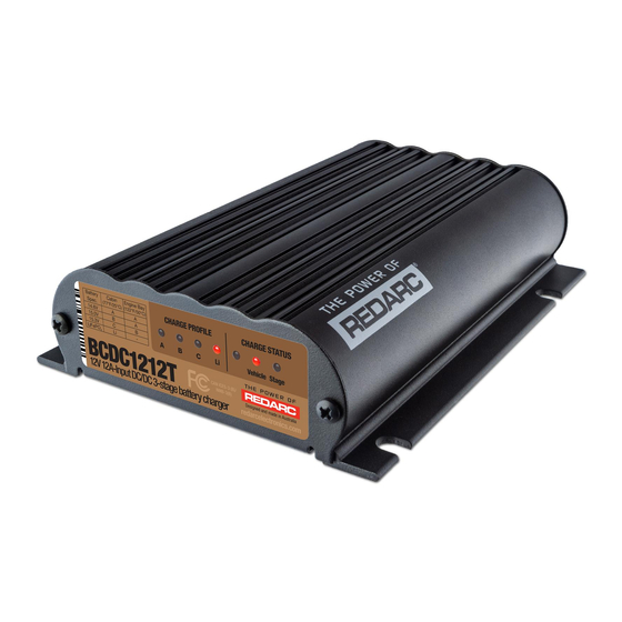
- Page 1 BCDC ® Multi-Stage 12 V Input Current Limited In-Vehicle Battery Charger MODEL: BCDC1212T ƒ...
-
Page 2: Table Of Contents
CONTENTS PRODUCT OVERVIEW ��������������������������������������������������������������� WARNINGS AND SAFETY INSTRUCTIONS ���������������������������� SPECIFICATIONS ������������������������������������������������������������������������ 1 PRODUCT FUNCTION ���������������������������������������������������������� 1.1 Display Panel ����������������������������������������������������������������� 1.2 Charge Profile LEDs ����������������������������������������������������� 1.3 Charge Status LEDs ����������������������������������������������������� 1.4 Charging Process ��������������������������������������������������������� Battery Test Mode ������������������������������������������������������� 1.6 Turn On/Off Thresholds ������������������������������������������������... -
Page 3: Product Overview
BCDC1212T Battery Charger. Do not operate the Battery Charger unless you have read and understood this manual and the Charger is installed as per these installation instructions. REDARC recommends that the Charger be installed by a suitably qualified person. SAFETY MESSAGE CONVENTIONS... - Page 4 2. Do NOT alter or disassemble the Battery Charger under any circumstances. All faulty units must be returned to REDARC for repair. Incorrect handling or reassembly may result in a risk of electric shock or fire and may void the unit warranty.
-
Page 5: Specifications
SPECIFICATIONS Part Number BCDC1212T Continuous Current Rating 12 A Input Fuse Rating 15 A to 23 A / 30 A (not supplied) Output Fuse Rating Vehicle Input Voltage Range* 9 to 32 V Nominal System Voltage 12 V 24 V Max. Rated Output Current... -
Page 6: Product Function
The BCDC1212T is a three-stage, 12 V DC-DC Battery Charger that operates from an alternator input of 12 V or 24 V. The input voltage to the BCDC1212T can be above, below or equal to the output voltage making it ideal for charging an auxiliary 12 V battery where the distance from the start battery or alternator may cause a significant voltage drop. -
Page 7: Charge Status Leds
3-Stage charging profile consisting of Boost, Absorption and Float Stages. Table 2 outlines the LED sequences which indicate these stages. See Figure 1 (page 8) information on the BCDC1212T charging process. Table 2: Stage LED Sequence LED Sequence Profile Stage (Lithium) -
Page 8: Charging Process
CHARGING PROCESS BOOST The Boost stage maintains a constant current until the battery voltage reaches its Absorption Voltage. The current in Boost stage may vary during operation in order to maintain safe operating temperature, or to limit the difference between input and output voltages. ABSORPTION The Charger will then move to Absorption stage which maintains a constant voltage level for a predetermined period of time or until the current being drawn by the output battery drops to less... -
Page 9: Turn On/Off Thresholds
TURN ON/OFF THRESHOLDS Input 12 V Vehicle Input 24 V Vehicle Input Input Trigger Settings Standard Standard Voltage Voltage Input Open Circuit Turn ON above 12.9 V 12.0 V 25.8 V 24.0 V Low voltage Turn OFF above 12.7 V 11.9 V 25.4 V 23.8 V... -
Page 10: Prior To Installation
2 PRIOR TO INSTALLATION INSTALLATION LOCATION The Charger is suitable for mounting in the trailer nose cone, cabin of the vehicle, along a chassis rail or in the engine bay (ensure the unit does not become covered by a build up of mud or other material and BCDC and wiring is not exposed to mechanical damage). -
Page 11: Cable Sizing
Fuses must be connected close to the auxiliary battery and start battery in order to protect the cabling and connectors between the batteries and the Battery Charger. REDARC recommends using MIDI style bolt down fuses as they ensure a low resistance connection. The REDARC FK23 and FK30 fuse kits are recommended. -
Page 12: Installation
3 INSTALLATION The heavy gauge cables on the BCDC1212T unit carry peak currents of up to 12 Amps, and it is important to make good, low resistance, electrical connections that will not degrade over time. Failure to make a good, reliable contact may result in breakdown of the cable insulation and cause a short circuit, or worst case a fire. -
Page 13: Start Battery Connection - Red Cable
START BATTERY CONNECTION — RED CABLE The RED (input) cable can be connected directly to the trailer plug’s +12 V auxiliary power pin, provided that towing harnesses and connectors are suitably rated (see CAUTION on page 11). Figure 8: Connecting the RED cable Start Battery Input Connect the RED cable to the positive input of the start battery using the appropriate fuse size. -
Page 14: Vehicle Ignition Input - Blue Cable
VEHICLE IGNITION INPUT — BLUE CABLE Vehicle Ignition The BLUE cable is required for vehicles with variable-voltage alternators to allow the BCDC1212T to operate in Low Voltage Mode. Connect to a signal which is active when the engine is running. Blue Wire For vehicles with fixed voltage alternators (standard alternator) the BLUE cable is not required and the BCDC1212T will operate in Standard Voltage Mode. -
Page 15: Standard Setup
STANDARD SETUP Figure 11: Typical Lad Acid Setup Optional LED with INPUT Resistor** GREEN Refer to Charging ORANGE Pro le Select INPUT YELLOW BLUE Standard Trigger Fuse* Settings Leave unconnected Loads or connect to Ground Fuse* Load 12 V or 24 V Fuse Start Battery Loads... -
Page 16: Troubleshooting
TROUBLESHOOTING There are no LEDs on at all... This indicates that there is no battery connected to the output (BROWN cable) or that the battery is not at a suitable voltage level to be charged AND the input (RED cable) if the Charger is not connected. -
Page 17: Frequently Asked Questions
The unit is also microprocessor controlled allowing it to output a REDARC proprietary charging algorithm independent of the input. This allows the unit to charge specific to the battery type even if the input voltage is low due to voltage drop. - Page 18 The most likely cause of this issue is that the BCDC is somehow 'stuck' in 24 V mode. Try removing the 'positive input' (RED) cable and reconnecting it. If the problem still exists please contact REDARC support team. FCC DECLARATION This device complies with Part 15 of the FCC Rules.
-
Page 19: Warranty
23 Brodie Road (North), Lonsdale South Australia 5160, Australia Design and specifications are subject to change without notice | Copyright © REDARC Electronics Pty Ltd� All rights reserved� REDARC®, THE POWER OF REDARC®, and BCDC® are trademarks of REDARC Electronics Pty Ltd�... - Page 20 Tech Support 1300 REDARC (1300-733-272) Australia +61 8 8322 4848 New Zealand +64 9 222 1024 UK & Europe +44 (0)20 3930 8109 +1 (704) 247-5150 Canada +1 (604) 260-5512 Mexico +52 (558) 526-2898 redarcelectronics.com INST55-8...
Need help?
Do you have a question about the BCDC1212T and is the answer not in the manual?
Questions and answers