
Related Manuals for Redarc BCDC2420


Summary of Contents for Redarc BCDC2420
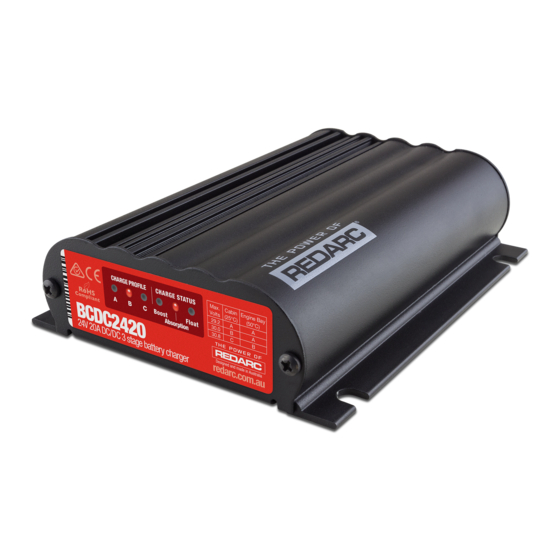
- Page 1 BCDC ® In-Vehicle 3-Stage 24V DC Battery Charger MODELS: BCDC2420 ƒ BCDC2420-LV ƒ CH AR GE PR OF ILE Ma x. Ca bin En gin e Ba y Vo lts (25 °C ) (50 °C ) 29 .2 30 .0...
-
Page 2: Table Of Contents
CONTENTS PRODUCT OVERVIEW �������������������������������������������������� WARNINGS AND SAFETY INFORMATION ���������������� SPECIFICATIONS ���������������������������������������������������������� PRODUCT FUNCTION �������������������������������������������������� 4.1. Display Panel �������������������������������������������������������������������� 4.2. Charging Process ������������������������������������������������������������� 4.3. Turn On/Off Thresholds ����������������������������������������������������� 4.4. Error Codes ���������������������������������������������������������������������� INSTALLATION �������������������������������������������������������������� 5.1. Install Location ������������������������������������������������������������������ 5.2. Cable Sizing���������������������������������������������������������������������� 5.3. -
Page 3: Product Overview
100%, regardless of their type or size. By providing a unique charging profile to each specific battery type, the BCDC2420(-LV) In-Vehicle Battery Chargers are able to achieve and maintain an optimal charge in your auxiliary battery, at all times. The BCDC2420(-LV) In-vehicle Battery Chargers also feature a Maximum... - Page 4 2. Do NOT alter or disassemble the Battery Charger under any circumstances. All faulty units must be returned to REDARC for repair. Incorrect handling or reassembly may result in a risk of electric shock or fire and may void the unit warranty.
-
Page 5: Specifications
SPECIFICATIONS Part Number BCDC2420 and BCDC2420-LV Continuous Current Rating 20 A Input Current Limit 32 A Input Fuse Rating 12 V/24 V 60 A / 40 A (Not supplied) Output Fuse Rating 30 A (Not supplied) Output Power 600 W 9 – 32 VDC ⎓ (9 – 16 VDC ⎓ for LV model) -
Page 6: Product Function
The BCDC2420(-LV) is a three-stage, 24 V DC-DC battery charger that operates from an alternator input of 12 V nominal or a 12 V nominal solar panel input. The BCDC2420 will also charge from an alternator input from a 24 V nominal vehicle . -
Page 7: Charging Process
4.2. CHARGING PROCESS BOOST The Boost stage maintains a constant current until the battery voltage reaches its Absorption Voltage. The current in Boost stage may vary during operation in order to maintain safe operating temperature, or to limit the difference between input and output voltages. ABSORPTION The Charger will then move to Absorption stage which maintains a constant voltage level for a predetermined period of time or until the current being drawn by the output battery drops to less... -
Page 8: Turn On/Off Thresholds
4.3. TURN ON/OFF THRESHOLDS 24 V 12 V 12 V Solar All (standard) BCDC2420 BCDC2420-LV Models BCDC2420 Input Open Turn ON ABOVE 12.9 V 12.0 V 17.5 V 26.4 V Circuit Low voltage Turn OFF BELOW 12.7 V 11.9 V 17.2 V... -
Page 9: Installation
Mount the unit to a flat surface close to the Figure 2: Mounting the Charger auxiliary battery and away from any heat sources. The BCDC2420(-LV) has six wires and should be installed as described over the following pages. The charger operates in any orientation (but it is recommended that the front of the decal be visible). -
Page 10: Fusing
The heavy gauge wires on the BCDC2420(-LV) unit carry peak currents of up to 40 Amps, and it is important to make a good, low resistance, electrical connection that will not degrade over time. -
Page 11: Auxiliary Battery Positive - Brown Wire
Figure 5: Ensuring a good wiring connection Crimp both wires to the butt splice using Solder the wires to the butt splice. Ensure single-indent type crimpers. Fold the cable over that a good connection is made. Keep before inserting into the butt-splice as required. heatshrink away until after soldering is Single-indent crimpers should also be used on complete and has cooled. -
Page 12: Source Select - Blue Wire
Ignition SOLAR INPUT The BCDC2420 is also capable of charging the auxiliary battery from a Solar source. The Unit will accept an input directly from an unregulated 12V nominal solar panels and act as a MPPT Solar Regulator. To select the Solar charging mode, the BLUE ‘Source Select’ wire can either be left disconnected or connected to GROUND. -
Page 13: Battery Type Select - Orange Wire
5.9. BATTERY TYPE SELECT — ORANGE WIRE The ORANGE wire is used to select the Maximum output voltage. This is achieved by connecting in the following way: Figure 11: Setting the Maximum Voltage (ORANGE wire) PROFILE A Leave the ORANGE wire disconnected to set the Maximum voltage to 29.2 V. -
Page 14: 5.11. Typical Setups
5.11. TYPICAL SETUPS REDARC recommends that the charger be installed by a suitably qualified person. Figure 13: BCDC2420 Standard Setup for a 12 V or 24 V Start Battery BCDC2420 Optional LED INPUT INPUT with Resistor*** GREEN Loads Load Fuse... - Page 15 A basic 3 V LED will not operate correctly if installed. ****A relay suitable for 12 V Vehicle installations is available as part of the REDARC RK1260 Relay Kit. The kit also includes butt-splice connectors, a wiring loom, heat shrink and instructions.
-
Page 16: Troubleshooting
SOLAR - BLUE to GROUND described on page 8 evident contact a quali ed or NO CONNECT, is the of this manual? Auto Electrician, or REDARC BLUE wire setup like this? Electronics. The BCDC is operating correctly. Are all battery negative... -
Page 17: Frequently Asked Questions
FREQUENTLY ASKED QUESTIONS The BCDC2420(-LV) turns ON at 12.9 V (12 V) and OFF at 12.7 V (11.9 V), but you say it operates down to 9 V, explain? The BCDC2420(-LV) will turn OFF for a split second every 100 seconds to measure the unloaded voltage at the battery. - Page 18 The most likely cause of this issue is that the BCDC is somehow ‘stuck’ in 24 V mode. Try removing the ‘Source Select’ (BLUE) wire and reconnecting it. If the problem still exists please contact REDARC Tech Support. 18 | Frequently asked questions...
-
Page 19: Warranty
For written request please email power@redarcelectronics.eu Design and specifications are subject to change without notice. | Copyright © REDARC Electronics Pty Ltd. All rights reserved. REDARC®, THE POWER OF REDARC® and BCDC® are trademarks of REDARC Electronics Pty Ltd. | REDARC®, THE POWER OF REDARC®... - Page 20 Tech Support 1300 REDARC (1300-733-272) Australia +61 8 8322 4848 New Zealand +64 9 222 1024 UK & Europe +44 (0)20 3930 8109 +1 (704) 247-5150 Canada +1 (604) 260-5512 Mexico +52 (558) 526-2898 redarcelectronics.com WARBCDC2420-5...
Need help?
Do you have a question about the BCDC2420 and is the answer not in the manual?
Questions and answers