Table of Contents
Advertisement
Quick Links
Advertisement
Table of Contents

Summary of Contents for Redarc BCDC1212T
- Page 1 Multi-stage 12 V Input Current Limited In-vehicle Battery Charger BCDC1212T...
-
Page 2: The Bcdc1212T
Design and specifications are subject to change without notice | Copyright © 2020 REDARC Electronics Pty Ltd. All rights reserved. | REDARC®, THE POWER OF REDARC®, and BCDC™ are trademarks of Redarc Electronics Pty Ltd. -
Page 3: Table Of Contents
CONTENTS THE BCDC1212T INSTALLATION WARNING AND SAFETY INSTRUCTIONS Install Location Charge Profile Selection (ORANGE Wire) 9 SPECIFICATIONS Input Trigger Settings (BLUE Wire) PRODUCT FUNCTION Cable sizing Wiring Display Panel Fusing Charge Profile LEDs Typical Setup Charge Status LEDs 1.3.1 Vehicle LED TROUBLESHOOTING 1.3.2 Stage LED... -
Page 4: Product Function
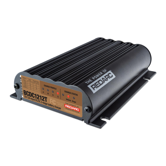
The BCDC1212T is a three-stage, 12 V DC-DC battery charger that operates from an alternator input of 12 V or 24 V. The input voltage to the BCDC1212T can be above, below or equal to the output voltage making it ideal for charging an auxiliary 12 V battery where the distance from the start battery or alternator may cause a significant voltage drop. -
Page 5: Charge Status Leds
PRODUCT FUNCTION AUXILIARY BATTERY LOCATION 50 + MAXIMUM BATTERY ENGINE BAY 75 F CABIN INSTALL 120 F VOLTAGE SPECIFICATION INSTALL 14.6 15.0 15.3 14.5 (LiFePO Not Recommended FIGURE 1.2.1: Charge Profile Selection Charge Status LEDs The Charge Status LEDs indicate to the user which inputs are available and what stage of the charge process the unit is currently in. -
Page 6: Optional External Led
PRODUCT FUNCTION 1.3.3 Optional External LED An option external LED (see Figures 2.7.1 and 2.7.2) can be used to provide charge status and error feedback away from the BCDC unit and is voltage limited to 9 V and current limited to 6 mA. A serial resistor and LED should be selected to these specifications. -
Page 7: Turn On/Off Thresholds
PRODUCT FUNCTION Turn On/Off Thresholds Input 12 V Vehicle Input 24 V Vehicle Input Input Trigger Standard Low Voltage Standard Settings Voltage Turn ON 12.9 V 12.0 V 25.8 V 24.0V Input above Open Circuit Low Turn OFF voltage conditions ** 12.7 V 11.9 V 25.4 V 23.8 V below Turn OFF 8.0 V... -
Page 8: Battery Test Mode
PRODUCT FUNCTION Battery Test Mode The unit features a battery test mode which occurs every 100 seconds. The test mode is designed to both test that the input conditions are still met and check for the presence of a battery on the output of the unit. -
Page 9: Charge Profile Selection (Orange Wire)
INSTALLATION Charge Profile Selection (ORANGE Wire) The ORANGE wire is used to select the Maximum output voltage. This is achieved by connecting in the following way: • To select Profile A leave the ORANGE wire disconnected. This will set the Maximum voltage to 14.6 V. •... -
Page 10: Input Trigger Settings (Blue Wire)
Cross Section (mm²) (BAE, B&S, AWG) (ft) 1 – 5 3 – 16 5.26 BCDC1212T 5 – 9 16 – 30 7.71 CAUTION Cable and fuse sizes are specified by various codes and standards which depend on the type of vehicle the Battery Charger is installed into. -
Page 11: Wiring
INSTALLATION Wiring The heavy gauge wires on the BCDC1212T unit carry peak currents of up to 25 Amps, and it is important to make good, low resistance, electrical connections that will not degrade over time. Failure to make a good, reliable contact may result in breakdown of the wire insulation and cause a short circuit, or worst case a fire. -
Page 12: Typical Setup
INSTALLATION Typical Setup Optional LED INPUT INPUT INPUT Green Charging Profile Select Orange Refer to section 2.2 Leave Loads unconnected Fuse* Standard Load Trigger Settings Fuse Fuse* to Vehicle 12V or 24V Ignition Low Voltage Start Battery Trigger Settings Bank All ground points must Auxiliary be connected to chassis... -
Page 13: Troubleshooting
The Serial Number Label contains the Part Number (circled in BLUE) and the Serial Number (circled in RED). The first 4 digits of the serial number indicate the YEAR and MONTH of manufacture, in the form YYMM. MADE IN AUSTRALIA BY REDARC ELECTRONICS PH (08)83224848 2007800851337 BCDC1212T... -
Page 14: Fcc Declaration
The BCDC can act as both a reducer and a booster, so it can operate from a voltage of above, equal to or below the desired output voltage. The unit is also microprocessor controlled allowing it to output a REDARC proprietary charging algorithm independent of the input. -
Page 15: Two Year Product Warranty - North America
20. REDARC shall not be responsible or liable to the Customer or any third party in connection or expenses, shipping costs to return non-conforming Products or any damages that may with any non-performance or delay in performance of any terms and conditions of this occur during the return of Product to REDARC. - Page 16 For product and technical support contact your regional distributor, call our head office between 8:00 a.m. to 5:30 p.m. Australian Central Standard Time, Monday to Friday, or send us an e-mail. Australia (and other Global regions) power@redarc.com.au www.redarc.com.au Para ver el +61 8 8322 4848...


Need help?
Do you have a question about the BCDC1212T and is the answer not in the manual?
Questions and answers