Novus N322 - Temperature Controller Manual
- Operator's manual (2 pages) ,
- Operating manual (2 pages) ,
- User manual (6 pages)
Advertisement
INTRODUCTION
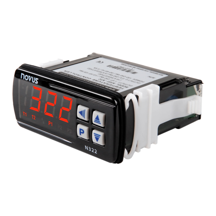
The N322 is a 2-output digital electronic controller for heating and cooling applications. It is available with NTC thermistor input sensor, Pt100, Pt1000 or J/K/T type thermocouple. Sensor offset correction is provided. The 2 independent outputs can be used as control or alarm. The features of a particular model (input sensor type, sensor range, mains supply, etc.) are identified by the label placed on the controller body.
SPECIFICATIONS
INPUT SENSOR: The sensor is chosen by the user at the time of purchase and is presented on the upper side of the equipment box. The options are:
- Thermistor NTC, 10 kΩ @ 25°C; Range: –50 to 120°C (–58 to 248°F); Accuracy: 0.6°C (1.1°F);
Maximum error in the interchangeability of original NTC sensors: 0.75°C (33.35°F). This error can be eliminated through the offset parameter of the equipment.
![warning]() Note: For the NTC thermistor option, the sensor comes with the equipment. Its operating range is limited to –30 to +105°C (–222 to +221°F). It has cable of 3 m in length, 2 x 0.5 mm², and can be extended up to 200 meters.
Note: For the NTC thermistor option, the sensor comes with the equipment. Its operating range is limited to –30 to +105°C (–222 to +221°F). It has cable of 3 m in length, 2 x 0.5 mm², and can be extended up to 200 meters. - Pt100; Range: –50 to 300°C (–58 to 572°F); α= 0,00385; 3 wires; Accuracy: 0.7°C (1.3°F); according to IEC-751 standards;
- Pt1000; Range: –200 to 530°C (–328 to 986 ºF); α= 0,00385; 3 wires; Accuracy: 0.7°C (1.3°F);
- Thermocouple type J; Range: 0 to 600°C (32 to 1112°F); Accuracy: 3°C (5.4°F);
- Thermocouple type K; Range –50 to 120°C (–58 to 248°F); Accuracy: 3°C (5.4°F);
- Thermocouple type T; Range: –50 to 120°C (–58 to 248°F); Accuracy: 3°C (5.4°F); Thermocouples according to IEC-584 standards.
WARM-UP: 5 minutes
MEASUREMENT RESOLUTION:
From –19.9 to 199.9 º with NTC, Pt100 and Pt1000: 0.1
Elsewhere: 1
 Note: The equipment keeps its precision all over the range, despite the lack of display resolution in a part of the range does not allow its visualization.
OUTPUT1: Relay SPDT; 1 HP 250 Vac / 1/3 HP 125 Vac (16 A Resistive)
OUTPUT2: Relay: 3 A / 250 Vac, SPST
POWER SUPPLY:
100~240 Vac (± 10%) or 24 Vdc/ac (12~30 Vdc/ac)
Mains frequency: 50~60 Hz. Power consumption: 5 VA

check the power supply specification before energizing the controller.
DIMENSIONS:
Width x Height x Depth: 74 x 32 x 75 mm
Panel cut-out: 70 x 29 mm; Weight: 100 g
ENVIRONMENT:
Operating temperature: 0 to 40°C (32 to 104°F)
Storage temperature: -20 to 60°C (-4 to 140°F)
Relative humidity: 20 to 85% non-condensing
CASE:
Polycarbonate UL94 V-2; Protection: Front panel: IP65, Box: IP42
Suitable wiring: Up to 4.0 mm²
RS-485 digital communication; RTU MODBUS protocol (optional)
Serial interface not isolated from input circuitry.
Serial interface isolated from input circuitry, except in 24 V powered model.
ELECTRICAL WIRING
It is important to follow the recommendations below:
- Signal wires should be installed in grounded conduits and away from power or contactor wires.
- The instrument should have its own power supply wires that should not be shared with electrical motors, coils, contactors, etc.
- Installing RC filters (47 R and 100 nF, series combination) is strongly recommended at contactor coils or any other inductors.
BACK PANEL
Fig. 1 below shows the controller connections to sensor, mains and outputs.

Fig. 1 – N322 terminals
Pt100 with 3 conductors: Terminals 11, 12 and 13 must have the same wire resistance for proper cable length compensation. For 2 wire Pt100, short circuit terminals 11 and 13.
OPERATION
The controller requires the internal parameters to be configured according to the intended use for the instrument. The parameters are organized in 4 groups or levels:
| Level | Function |
| 0 | Temperature measurement |
| 1 | Setpoint Adjustment |
| 2 | Configuration |
| 3 | Calibration |
Upon power-up, the N322 display shows for 1 second its firmware version. This information is useful when consulting the factory.
Then, the temperature measured by the sensor is shown on the display. This is the parameter level 0 (temperature measurement level).
To access level 1, press  for 1 second until the "
 " message shows up. Pressing again, the "
 " parameter is presented. To go back to level 0, press once more.
To access level 2 of parameters, press for 2 seconds until the " " message is shown. Release the key to remain in this level. Each new pressing on the key will advance to the next parameter in the level. At the end of the level, the controller returns to the first level (0). Use the
  and
and  keys to alter a parameter value.
Notes:
- A parameter configuration is saved when the
![]() key is pressed to advance to the next parameter in the cycle. The configuration is stored in a non-volatile memory, retaining its value when the controller is deenergized.
key is pressed to advance to the next parameter in the cycle. The configuration is stored in a non-volatile memory, retaining its value when the controller is deenergized. - If no keyboard activity is detected for over 20 seconds, the controller saves the current parameter value and returns to the measurement level.
Level 1 –Setpoint Adjustment
In this level only the Setpoint ( and
and  ) parameters are available, alternating the names with their respective values. Adjust the desired temperature for each setpoint clicking on the and keys.
| Set Point 1 | Temperature adjustment for control OUTPUT 1. value is limited to the values programmed in  and and  in the programming level (Parameter configuration, level 2). in the programming level (Parameter configuration, level 2). |
| Set Point 2 | Temperature adjustment for control OUTPUT 2. value is limited to the values programmed in and |
Level 2 – Configuration - Parameters configuration Level
Contains the configuration parameters to be defined by the user, according to the system's requirements. Use and keys to set the value. The display alternates the parameter name and respective value.
 | Temperature Unit - Selects display indication for degrees Celsius or Fahrenheit. – Temperature in degrees Celsius – Temperature in degrees Celsius - Temperature in degrees Fahrenheit - Temperature in degrees Fahrenheit | ||
 | Input Type - Selects the input sensor type to be connected to the controller. Available only for thermocouple models, allowing selection of types J, K and T.
| ||
 | Sensor Offset - Offset value to be added to the measured temperature to compensate sensor error. | ||
 | SP Low Limit - Lower range for SP1 and SP2. SPL must be programmed with a lower value than spK. | ||
 | SP High Limit - Upper range for SP1 and SP2. SPx must be greater than spl. | ||
 | OUTPUT 1 Hysteresis: defines the differential range between the temperature value at which the OUTPUT 1 is turned on and the value at which it is turned off. In degrees. | ||
 | OUTPUT 2 Hysteresis: defines the differential range between the temperature value at which the OUTPUT 2 is turned on and the value at which it is turned off. In degrees. | ||
 | Control action for OUTPUT 1: Reverse: For heating applications. Outputs turn on when temperature is lower than SP. Reverse: For heating applications. Outputs turn on when temperature is lower than SP. Direct: For cooling applications. Output turns on when temperature is above SP. Direct: For cooling applications. Output turns on when temperature is above SP. | ||
 | Action 2 - Control OUTPUT 2 action or Alarm functions:
The section Working with the Controller describes how these functions work. | ||
 Control | Control - Associates Setpoints and Outputs.  Setpoint 1 is assigned to OUTPUT1 and Setpoint 2 to OUTPUT2 (factory setting). Setpoint 1 is assigned to OUTPUT1 and Setpoint 2 to OUTPUT2 (factory setting). Setpoint 1 is assigned to OUTPUT2 where as Setpoint 2 is directed to OUTPUT1. Setpoint 1 is assigned to OUTPUT2 where as Setpoint 2 is directed to OUTPUT1. | ||
 Off time 1 | Off time 1 - Defines the minimum off time for control OUTPUT 1. Once OUTPUT 1 is turned off, it remains so for at least the time programmed in  . For thermocouple inputs this parameter is not available. This parameter is intended for refrigeration systems where longer compressor life is desired. For heating systems, program . For thermocouple inputs this parameter is not available. This parameter is intended for refrigeration systems where longer compressor life is desired. For heating systems, program  to zero. to zero.Value in seconds, 0 to 999 s. | ||
 on time 1 | On time 1 - Defines the minimum on time for control OUTPUT 1. Once turned on, OUTPUT 1 remains so for at least the time programmed in  . For thermocouple inputs this parameter is not available. This parameter is intended for refrigeration systems where increased compressor life is desired. For heating systems, program to zero. . For thermocouple inputs this parameter is not available. This parameter is intended for refrigeration systems where increased compressor life is desired. For heating systems, program to zero.Value in seconds, 0 to 999 s. | ||
 Delay 1 | Delay 1 - Delay time to start control. Upon power-on, control OUTPUT 1 is kept off until the time programmed in  is elapsed. Its usage is intended to prevent multiple compressors to start simultaneously after the turn-on of a system with several controllers. Value in seconds, 0 to 250 s. is elapsed. Its usage is intended to prevent multiple compressors to start simultaneously after the turn-on of a system with several controllers. Value in seconds, 0 to 250 s. | ||
 Off time 2 | Off time 2 - Defines the minimum off time for control OUTPUT 2. Once OUTPUT 2 is turned off, it remains so for at least the time programmed in  . For thermocouple inputs this parameter is not available. This parameter is intended for refrigeration systems where increased compressor life is desired. For heating systems, program to zero. . For thermocouple inputs this parameter is not available. This parameter is intended for refrigeration systems where increased compressor life is desired. For heating systems, program to zero.Value in seconds, 0 to 999 s. | ||
 on time 2 | On time 2 - Defines the minimum on time for control OUTPUT 2. Once turned on, OUTPUT 2 remains so for at least the time programmed in . For thermocouple inputs this parameter is not available. This parameter is intended for refrigeration systems where increased compressor life is desired. Value in seconds, 0 to 999 s. For heating systems, program to zero. | ||
 Delay 2 | Delay 2 - Delay time for OUTPUT 2 to turn on relative to OUTPUT 1. This parameter defines a particular working mode, typically used in multiple stage systems, where OUTPUT 2 is allowed to go on only if OUTPUT 1 is already on for at least  seconds. Also, OUTPUT 2 is driven off whenever OUTPUT 1 goes off. seconds. Also, OUTPUT 2 is driven off whenever OUTPUT 1 goes off.  = =  disables this function. Value in seconds, 0 to 250 s. disables this function. Value in seconds, 0 to 250 s. | ||
 Address | Address - Controllers with the optional RS485 Modbus RTU communication interface have the  parameter at the Configuration level. Set a unique Modbus address for each equipment connected to the network. Address range is from 1 to 247. parameter at the Configuration level. Set a unique Modbus address for each equipment connected to the network. Address range is from 1 to 247. | ||
 - Thermocouple type T
 Direct control action (cooling).
 Low (minimum) temperature alarm.
 High (maximum) temperature alarm.
 Alarm for temperature inside the range
 Alarm for temperature outside the range.
 Low temperature alarm with initial blocking.
 High temperature alarm with initial blocking.
 Inside range alarm with initial blocking.
 Outside range alarm with initial blocking.
Level 3 – Calibration level
The controller is factory calibrated. The following parameters should be accessed only by experienced personnel. To enter this cycle, the  key must be kept pressed for 4 seconds.
Don't press the  and
and  keys if you are not sure of the calibration procedures. Just press the key a few times until the temperature measurement level is reached again.
 | Password - Enter the correct password to unlock write operations for the parameters in the following levels. | |||
 | Calibration low - Offset value of the input. It adjusts the lower measurement range of the sensor. | |||
 | Calibration High - Gain calibration. It adjusts the upper measurement range of the sensor. | |||
 | Cold Junction Offset calibration - This parameter is available only for thermocouple. | |||
 | Factory Calibration - Restores factory calibration parameters. Change from 0 to 1 restores the calibration parameters with factory values. | |||
 | Protection - Defines the levels of parameters that will be password protected. See "Configuration Protection" for details. | |||
 | Password Change - Allows changing the current password to a new one. Values from 1 to 999 are allowed. | |||
 | Serial number - First part of the controller electronic serial number. | |||
 | Serial number - Second part of the controller electronic serial number. | |||
 | Serial number - Third part of the controller electronic serial number. | |||
WORKING WITH THE CONTROLLER
Multiple output controllers are suited for controlling multiple stage systems.
Other applications require OUTPUT 1 to be the control output and OUTPUT 2 to be the alarm.
There are eight distinct alarm functions implemented in OUTPUT 2, selected by the parameter  , described below:
 - Low temperature alarm – OUTPUT 2 is turned on when the measured temperature falls below the
  value.
 - High temperature alarm – OUTPUT 2 is turned on when the measured temperature exceeds the value programmed in .
 - Inside range alarm – OUTPUT 2 is turned on when the measured temperature is within the range defined by:
 and
and 
 - Outside range alarm: OUTPUT 2 is turned on when the temperature falls outside the range defined by:
 and
and 
Functions  are identical to the above ones except that they incorporate the Initial Blocking feature, which inhibits the output if an alarm condition is present at start-up. The alarm will be unblocked after the process reaches a non-alarm condition for the first time.
In a multiple stage application,  and
and  are configured to operate at different temperatures, creating a progressive sequence for turning on the outputs (compressors) in response to a system demand. The output delays for turning on the compressors (
 and
and  ) cause the compressors to be turned on one by one, minimizing energy demand.
Another usage for multiple output controllers is in systems that require automatic selection between cool and heat action. In these applications, one output is configured as reverse action (heating) and the other as direct action (refrigeration). The output status led P1 and P2 in the controller panel, signals when the control output in on.
CONFIGURATION PROTECTION
A protection system to avoid unwanted changes to the controller parameters is implemented. The level of protection can be selected from partial to full. The following parameters are part of the protection system:
 | When this parameter is presented, the correct password should be entered to allow changes of parameters in the following levels. |
 | Defines the level of parameters that will be password protected:
|
 | Parameter for definition of a new password. Since it is located in the calibration level, can only be changed by a user that knows the current password. Valid passwords are in the range 1 to 999. |
Configuration protection usage
 parameter is displayed before entering a protected level. If the correct password is entered, parameters in all following levels can be changed. If wrong or no password is entered, parameters in the following levels will be read only.

- After five consecutive attempts to enter a wrong password, new tentative will be blocked for the next 10 minutes. If the current valid password is unknown, the master password can be used only to define a new password for the controller.
- The password for a brand new device is 111.
MASTER PASSWORD
The master password allows user to define a new password for the controller, even if the current password is unknown. The master password is based in the serial number of the controller, and calculated as following:
[ 1 ] + [ higher digit of SN2 ] + [ higher digit of SN1 ] + [ higher digit of SN0 ]
For example the master password for the device with serial number 987123465 is:
1 9 3 6 as follows: 1 +  = 987;
  = 123;
  = 465 = 1 + 9 + 3 + 6
How to use the master password:
- Enter the master password value at
![]() prompt.
prompt. - Go to
![]() parameter and enter the new password, which must not be zero (0).
parameter and enter the new password, which must not be zero (0). - Now you can use this new password to access all controller parameters with modify rights.
 prompt.
 parameter and enter the new password, which must not be zero (0).
ERROR MESSAGES
Sensor measurement errors force the controller outputs to be turned off. The cause for these errors may have origin in a bad connection, sensor defect (cable or element) or system temperature outside the sensor working range. The display signs related to measurement errors are shown below:
 | Measured temperature exceeded maximum allowed range for the sensor. Broken Pt100, Pt1000 or T/C. Short circuited NTC sensor. |
 | Measured temperature is below minimum measurement range of the sensor. Short circuited Pt100, Pt1000 or T/C. Broken NTC. |
WARRANTY
Warranty conditions are available on our website www.novusautomation.com/warranty.

Documents / Resources
References
Download manual
Here you can download full pdf version of manual, it may contain additional safety instructions, warranty information, FCC rules, etc.
Advertisement


Need help?
Do you have a question about the N322 and is the answer not in the manual?
Questions and answers