Advertisement
Quick Links
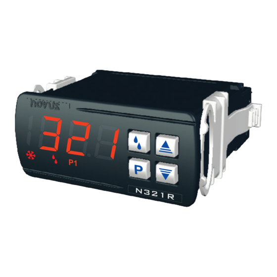
TEMPERATURE CONTROLLER
N321R
OPERATING MANUAL V1.8x F
The N321R is a controller for cooling applications, with defrost function (forced compressor
shut-down). It accepts NTC, Pt100 and Pt1000 temperature probes, depending on the
product code (the user must observe the measurement range of the selected sensor). The
N321R control output is capable of driving a compressor load of up to 1 HP directly.
The features of a particular model (input sensor type, sensor range, mains supply, etc) are
identified by the label placed on the thermometer body.
SPECIFICATIONS
SENSOR INPUT: The sensor is chosen by the user at the time of purchase and is presented
on the upper side of the equipment box. The options are:
• Thermistor NTC, 10 kΩ @ 25 °C; Range: -50 to 120 °C (-58 to 248 °F);
Accuracy: 0.6 °C (1.1 °F);
Maximum error in the interchangeability of original NTC sensors: 0.75 °C (1.35 °F). This
error can be eliminated through the offset parameter of the equipment.
Note: For the NTC thermistor option, the sensor comes with the equipment. Its
operating range is limited to -30 to +105 °C (-222 to +221 °F). It has cable of 3 meters
in length, 2 x 0.5 mm², and can be extended up to 200 meters.
• Pt100; Range: -50 to 300 °C (-58 to 572 °F); α= 0,00385; 3 wires;
Accuracy: 0.7 °C (1.3 °F); according to IEC-751 standards;
• Pt1000; Range: –200 to 530 °C (-328 to 986 ºF); α= 0,00385; 3 wires;
Accuracy: 0.7 °C (1.3 °F).
Measurement Resolution:............................................................... 0.1 º from -19.9 to 199.9 º
..................................................................................... 1 ºC elsewhere
Note: The equipment keeps its precision all over the range, despite the lack of display
resolution in a part of the range does not allow its visualization.
OUTPUT1: ............................... Relay SPDT; 1 HP 250 Vac / 1/3 HP 125 Vac (16 A Resistive)
POWER SUPPLY:
......................................... 100 to 240 Vac/dc (± 10 %)
Optionally: ................................................ 12 to 30 Vdc
Mains frequency: .......................................... 50~60 Hz
Power consumption: ............................................. 5 VA
Dimensions:
Width x Height x Depth: ............................................ 75 x 33 x 75 mm
Weight: .......................................................................................100 g
Panel cut-out: .................................................................... 70 x 29 mm
Environment:
Operating temperature: ........................ 0 to 40 °C (32 to 104 ºF)
Storage temperature: ........................ -20 to 60 °C (-4 to 140 ºF)
Relative humidity: ................................................. 20 to 85 % RH
Protection: Box IP42, Frontal panel IP65
Serial interface not isolated from input circuitry.
Serial interface isolated from input circuitry, except in 24 V powered model.
ELECTRICAL WIRING
Fig. 01 below shows the controller connections to sensor, mains and outputs.
* The serial communication interface is optional.
Pt100 with 3 conductors: Terminals 11, 12 and 13 must have the same wire resistance for
proper cable length compensation. For 2 wire Pt100, short circuit terminals 11 and 13.
Recommendations for the Installation
• Temperature sensor drivers must go through the plant separate system for drivers of
control output and power supply if possible electroducts terrified.
• The controller's power should come preferably a campus network for instrumentation or
different from that used by phase control output.
• Installing RC filters (47 R and 100 nF, series combination) is strongly recommended at
contactor coils or any other inductors.
OPERATION
The controller requires the internal parameters to be configured according to the intended
use for the instrument.
The parameters are organized in 4 groups or levels.
Level
0
1
2
3
Upon power-up, the controller display shows for 1 second its firmware version. This
information is useful when consulting the factory. Then, the temperature measured by the
sensor is shown on the display. This is the parameter level 0 (temperature measurement
level).
To access level 1, press
Case Polycarbonate UL94 V-2
again to go back to level 0.
To access level 2 of parameters, press
Suitable wiring: Up to 4.0 mm²
Release the
to the next parameter in that level. At the end of the level, the controller returns to the first
level (0).
Use the
Notes:
Fig. 01 - N321R terminals
Function
Temperature Measurement
Setpoint Adjustment / Voltage indication
Configuration
Calibration
for 1 second until the "SP" message shows up. Pressing
for 2 seconds until the "uNT" message is shown.
key to remain in this level. Each new pressing on the
and
keys to alter a parameter value.
1
A parameter configuration is saved when the
advance to the next parameter in the cycle. The configuration is stored in a
non-volatile memory, retaining its value when the controller is de-energized.
2
If no keyboard activity is detected for over 20 seconds, the controller saves
the current parameter value and returns to the measurement level.
Level 1 – Setpoint Adjustment
In this level only the Setpoint (SP) parameters are available, alternating the names with their
respective values. Adjust the desired temperature for each setpoint clicking on the
keys.
The screen voltage measurement. For values lower than 150 Vac and
U
higher than 254 Vac presents the message 0.
Voltage
Function available only for model N321R-NTC-LVD.
Temperature adjustment for control OUTPUT 1. SP value is limited to the
SP
values programmed in SPL and SPk in the programming level (Parameter
Set Point
Configuration, Level 2).
Level 2 – Configuration – Parameters Configuration Level
Contains the configuration parameters to be defined by the user, according to the system's
requirements. Use
and
name and respective value.
Temperature Unit. Selects display indication for degrees Celsius or
Unt
Fahrenheit.
0 Temperature in degrees Celsius. (factory default)
1 Temperature in degrees Fahrenheit.
Sensor Offset - Offset value to be added to the measured temperature to
ofs
compensate sensor error.
SP Low Limit - Lower range for SP. SPL must be programmed with a
spl
lower value than spK.
SP High Limit - Upper range for SP. SPx must be greater than spl.
spK
OUTPUT 1 Hysteresis: Defines the differential range between the OUTPUT
kys
1 temperature value at which it is turned off. In degrees.
Histeresis
Off time - Defines the minimum off time for control OUTPUT 1. Once
oft
OUTPUT 1 is turned off, it remains so for at least the time programmed in
oft. This parameter is intended for refrigeration systems where longer
compressor life is desired. Value in seconds, 0 to 999 s.
On time - Defines the minimum on time for control OUTPUT 1. Once turned
ont
on, OUTPUT 1 remains so for at least the time programmed in ont. For
thermocouple inputs this parameter is not available. This parameter is
intended for refrigeration systems where increased compressor life is desired.
For heating systems, program ont to zero. Value in seconds, 0 to 999 s.
Delay time to start control. Upon power-on, control OUTPUT 1 is kept off
dly
until the time programmed in dly is elapsed.
Delay
Its usage is intended to prevent multiple compressors to start
simultaneously after the turn-on of a system with several controllers.
Value in seconds, 0 to 250 s.
dib
Time base for dfi:
Defrost
0 Seconds
Interval Base
dtb
key will advance
Time base for dft:
Defrost Time
0 Seconds
Base
Interval between defrost cycles. Can be selected 0 to 999 seconds/
dfi
minutes/hours, according the value specified at dib.
Defrost
interval
key is pressed to
Defrost duration. Can be 1 to 999 seconds / minutes / hours, according the
Dft
value specified at dtb.
Defrost time
Hold the temperature indication throughout the defrost interval or the time
dfh
defined by this parameter.
Defrost hold
0
1 to 250
and
keys to set the value. The display alternates the parameter
Minutes
Hours
1
2
Minutes
Hours
1
2
Do not hold the indication during the defrost;
Time (seconds / minutes / hours) besides the defrost time
the indication will remain held.
Advertisement

Related Manuals for Novus N321R


Summary of Contents for Novus N321R
- Page 1 (the user must observe the measurement range of the selected sensor). The Function available only for model N321R-NTC-LVD. N321R control output is capable of driving a compressor load of up to 1 HP directly. Temperature adjustment for control OUTPUT 1. SP value is limited to the...
- Page 2 The display signs related to measurement errors are shown below. Function available only for model N321R-NTC-LVD. The defrost process of this controller is executed by stopping the compressor. This procedure is done every time interval defined by the user. The control output remains off by Determines a delay in the compressor shutting down when compressor •...
Need help?
Do you have a question about the N321R and is the answer not in the manual?
Questions and answers