Table of Contents
Advertisement
Quick Links
N321, N322, N323
TEMPERATURE CONTROLLERS
USER GUIDE - V1.8x / V2.0x
1.
SAFETY ALERTS
The symbols below are used in the device and throughout this
manual to draw the user's attention to valuable information related to
device safety and use.
CAUTION:
Read the manual fully before
installing and operating the
device.
All safety recommendations appearing in this manual must be
followed to ensure personal safety and prevent damage to the
instrument or system. If the instrument is used in a manner other
than that specified in this manual, the device's safety protections may
not be effective.
2.
SUMMARY
1.
SAFETY ALERTS ...................................................................................... 1
2.
SUMMARY ................................................................................................. 1
3.
INTRODUCTION ....................................................................................... 1
4.
SPECIFICATIONS ..................................................................................... 1
5.
ELECTRICAL CONNECTIONS ................................................................. 2
5.1
N321 MODEL ..................................................................................... 2
5.2
N322 MODEL ..................................................................................... 2
5.3
N323 MODEL ..................................................................................... 3
5.4
INSTALLATION RECOMMENDATIONS........................................... 3
6.
OPERATION .............................................................................................. 3
6.1
LEVEL 1 - SETPOINT ADJUSTMENT LEVEL ................................. 3
6.2
LEVEL 2 - OPERATION MODE LEVEL ........................................... 3
6.3
LEVEL 3 - CALIBRATION LEVEL .................................................... 4
7.
OPERATION .............................................................................................. 5
7.1
N321 MODEL: OPERATION ............................................................. 5
7.2
N322 AND N323 MODELS: OPERATION ........................................ 5
7.3
N322 AND N323 MODELS: ALARM FUNCTIONS ........................... 5
7.4
N323 MODEL: ALARM TIMER .......................................................... 5
8.
CONFIGURATION PROTECTION ............................................................ 5
8.1
CONFIGURATION PROTECTION OPERATION ............................. 6
9.
MASTER PASSWORD .............................................................................. 6
9.1
HOW TO USE YOUR MASTER PASSWORD .................................. 6
10. ERROR INDICATION ................................................................................ 6
11. SERIAL COMMUNICATION ...................................................................... 6
11.1 FEATURES ........................................................................................ 6
11.2 PARAMETER CONFIGURATION ..................................................... 6
11.3 COMMUNICATION PROTOCOL ...................................................... 6
11.4 REGISTER TABLE ............................................................................ 6
12. WARRANTY .............................................................................................. 6
NOVUS AUTOMATION
CAUTION OR HAZARD:
Risk of electric shock.
3.
INTRODUCTION
N321, N322, and N323 are temperature controllers for heating and
cooling. They are distinguished by the number of outputs available:
N321: It has 1 output channel: OUT1.
•
N322: It has 2 output channels: OUT1 and OUT2.
•
N323: It has 3 output channels: OUT1, OUT2, and OUT3.
•
The models are subdivided by the type of temperature sensor
supported:
NTC: Model accepting only the NTC sensor.
•
Pt100: Model accepting only the Pt100 sensor.
•
J/K/T: Model accepting only J, K and T sensors.
•
The features of each controller are in accordance with the purchase
order and are shown on the label attached to the body of the
controller itself.
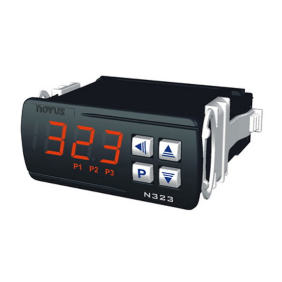
Example of the label of an N323 model:
Figure 1 -
These models may have differences in power supply and the
availability of an RS485 communication channel.
4.
SPECIFICATIONS
Sensor Input: The choice of sensor is made at the time of purchase
and shown on the controller identification label. There are three
options:
NTC Input:
Type: ............ NTC Thermistor, 10 kΩ @ 25 °C; β25/85 = 3435 K; 1 %
Measurement range: .............................. -50 to 120 °C (-58 to 248 °F)
Measurement accuracy: ....... 0.6 °C/F between -19.9 and 99.9 °C/F
............................................................................. 1 °C/F elsewhere
Pt100 Input:
Type: ............................................................................. Pt100, α = 385
Measurement range: .............................. -50 to 300 °C (-58 to 572 °F)
Measurement accuracy: ........................ 0.2 % F.S. ± 2 °C @ 25 °C
J/K/T Input:
Measurement range J: ................................ 0 to 600 °C (32 to 999 °F)
Measurement range K: ............................ -50 to 999 °C (32 to 999 °F)
Identification label
1/6
Advertisement
Table of Contents

Related Manuals for Novus N321


Summary of Contents for Novus N321
- Page 1 INTRODUCTION The symbols below are used in the device and throughout this N321, N322, and N323 are temperature controllers for heating and manual to draw the user’s attention to valuable information related to cooling. They are distinguished by the number of outputs available: device safety and use.
- Page 2 Measurement accuracy: ......0.2 % F.S. ± 2 °C @ 25 °C N321 MODEL Notes: The figures below show the connection terminals for the N321 1. All input types are factory calibrated. sensor, power supply, and output: 2. The thermocouples follow the NBR 12771/99 standard.
- Page 3 N321, N322, N323 conductors must all have the same electrical resistance (cross- 1. The controller saves the programming when you move from section). one parameter to another. Only then will it be considered valid. 2. If the keys are not used for a time longer than 20 seconds, the...
- Page 4 N321, N322, N323 Within-range alarm with initial blocking. Time interval T2 for alarm timing. Defines the timed action of alarms, as shown in Out-of-range alarm with initial blocking. Table 2. Timer T2 Parameters available only for N322 and N323 Adjustable between 0 and 1999 seconds.
- Page 5 N321, N322, N323 OPERATION Functions 6, 7, 8, and 9 are identical to the functions mentioned in this section, but they have the Initial Alarm Blocking feature, which N321 MODEL: OPERATION blocks the alarm (does not allow it to activate) when the controller initiates control already in an alarm condition.
- Page 6 N321, N322, N323 CONFIGURATION PROTECTION OPERATION The RS485 signals are: D0 ���� D - A The PAS parameter appears at the beginning of the protected level. D1 D D + B Bidirectional data line. If you enter the password correctly, you can change the parameters Inverted bidirectional data line.
Need help?
Do you have a question about the N321 and is the answer not in the manual?
Questions and answers