Advertisement
INTRODUCTION
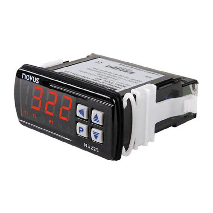
The N322S is a controller intended for solar water heating applications. It controls the water circulation system based on the difference of temperature between the solar collector and the storage tank (or swimming pool).
The instrument contains two NTC-type temperature sensors and two outputs: a control output (output 1) for activating the water circulation pump and a booster output or support output (output 2). It provides protections against overheating and freezing to the piping, preventing damages to the system.
SPECIFICATIONS
INPUT SENSOR:
- Thermistor NTC, 10 kΩ @ 25°C; Range: –50 to 120°C (–58 to 248°F); Accuracy: 0.6°C (1.1°F);
Maximum error in the interchangeability of original NTC sensors: 0.75°C (33.35°F). This error can be eliminated through the offset parameter of the equipment.
Note: For the NTC thermistor option, the sensor comes with the equipment. Its operating range is limited to –30 to +105°C (–222 to +221°F). It has cable of 3 m in length, 2 x 0.5 mm², and can be extended up to 200 meters.
Measurement Resolution: 0.1 º from –19.9 to 119.9 º
1 ºC elsewhere
Note: The equipment keeps its precision all over the range, despite the lack of display resolution in a part of the range does not allow its visualization.
Circulation Output (OUTPUT1): Relay SPDT
1 HP 250 Vac / 1/3 HP 125 Vac (16 A Resistive)
Support Output (OUTPUT2): Relay: 3A / 250 Vac, SPST
POWER SUPPLY: 100 to 240 Vac/dc ± 10%
Optionally: 12 to 30 Vdc/ac
Mains Frequency: 50~60 Hz
Power Consumption: 5 VA
DIMENSIONS: Width x Height x Depth: 75 x 34 x 75 mm
Weight: 100 g
Panel: 70 x 29 mm
ENVIRONMENT:
Operating: 0 to 40°C (32 to 104 ºF)
Storage temperature: -20 a 60°C (-4 to 140 ºF)
Relative humidity: 20 to 85% non-condensing
CASE: Polycarbonate UL94-2; Protection: Front panel: IP65, Box: IP42
Suitable wiring: Up to 4.0 mm2
RS-485 digital communication; RTU MODBUS protocol (Optional) Serial interface not isolated from input circuitry. Serial interface isolated from power supply input, except in 24 V models.
INSTALLATION
It is important to follow the recommendations below:
- Signal wires should be installed in grounded conduits and away from power or contactor wires.
- The instrument should have its own power supply wires that should not be shared with electrical motors, coils, contactors, etc.
- Installing RC filters (47 R and 100 nF, series combination) is strongly recommended at contactor coils or any other inductor.
- Use protection devices like circuit breakers and fuses.
ELECTRICAL WIRING
Fig. 1 below shows the controller connections to sensor, mains and outputs.

OUTPUT1 is the Circulation Output.
OUTPUT2 is the Support Output.
* The serial communication interface is optional.
OPERATION
The N322S contains several parameters that need to be configured in order to determine system behavior.
These configuration parameters are organized in groups, the so called parameter levels.
| Level | Function |
| 0 | Temperature Measurement |
| 1 | Setpoint Adjustment |
| 2 | Configuration |
| 3 | Calibration |
Upon power-up, the N322S display shows for 1 second its firmware version. This information is useful when consulting the factory.
Then, the temperatures of the sensors are displayed, according to the scheme defined in the parameter " ". This is the parameter level 0 (temperature measurement level).
For accessing the level 1, press the  key for 2 seconds until the "
 " parameter appears. Release the key to remain on this level Pressing the key successively the other parameters in this level are displayed.
For accessing the level 2, press the key for 4 seconds until the " " parameter appears. Release the key to remain on this level. Press again to access the other parameters of this level. After reaching the last parameter, the controller will return to the temperature measurement level.
Use the  and
and  keys to alter a parameter value. The display alternates the parameters prompts and their respective value.
Notes:
- The configuration will be saved by the controller upon advancing to the next parameter in a level.
- If no keypad activity is detected within 20 seconds, the controller saves the current parameter value and returns to the measurement level.
Level 1 – Setpoint Adjustment
At this level, the display presents the setpoint parameters. They define the differential temperatures values for the control. Use the and keys for setting the suitable values.
 | Differential setpoint for activating the pump. When the difference between T1 and T2 is higher than the value configured in  the pump will be turned on. the pump will be turned on.Max  value: 20 ºC. value: 20 ºC. |
 | Differential setpoint for deactivating the pump. When the difference between T1 and T2 is lower than the value configured in the pump will be turned off.Adjustable between 1 ºC and . |
 | Setpoint for activating booster output. Adjustable between  and and  . . |
Level 2 – Programming Level
This level contains other configuration parameters that are needed for establishing a proper system performance.
 Unit | Temperature Unit – Defines the temperature unit to be displayed. Temperature in degrees Celsius Temperature in degrees Celsius Temperature in degrees Fahrenheit Temperature in degrees Fahrenheit |
 Indication | Temperature value exhibited on the display.Temperature of the collectors (T1)Temperature of the storage tank (T2) Temperature difference between the sensors (T1 –T2) Temperature difference between the sensors (T1 –T2) Alternates the indication of (T1), (T2) and (T1-T2) at every 3s. Alternates the indication of (T1), (T2) and (T1-T2) at every 3s. |
 Ice | Setpoint for low temperature. When the temperature in the solar collector is lower than the value here configured, the pump is turned on, preventing the water from freezing in the pipe system and causing damages to it. Adjustable between  and and  . . |
 High Temperature 1 | Setpoint for high temperature (at collector). When the temperature in the collector is above the value here configured, the pump is turned off, avoiding the overheated water from damaging the pipe system. Adjustable between and . |
 High Temperature 2 | Setpoint for high temperature at S2 (storage tank). When the temperature at the sensor S2 is above the value here configured, the pump is turned off in order to avoid thermal discomfort. This function is useful in swimming pool heating systems which do not use dedicated third sensor. Adjustable between and . |
 Action 1 | Action type for booster output (SP1): Reverse Action Control. Good for heating. Turns on the booster output when temperature is below SP1. Reverse Action Control. Good for heating. Turns on the booster output when temperature is below SP1. Direct Action Control. Good for cooling. Turns on the booster output when temperature is higher than SP1. Direct Action Control. Good for cooling. Turns on the booster output when temperature is higher than SP1. |
 Histeresis | Antifreezing temperature hysteresis of sensor S1 ( ). In degrees. Adjustable between 0.1 and 50.0 ºC ). In degrees. Adjustable between 0.1 and 50.0 ºC |
 Histeresis 1 | Overheating temperature hysteresis of sensor S1 ( ). In degrees. Adjustable between 0.1 and 50.0 ºC ). In degrees. Adjustable between 0.1 and 50.0 ºC |
 Histeresis 2 | Overheating temperature hysteresis of sensor S2 ( ). In degrees. Adjustable between 0.1 and 50.0°C. ). In degrees. Adjustable between 0.1 and 50.0°C. |
 Booster | Booster output 1 activating temperature hysteresis ( ). ).Adjustable between 0.1 and 50.0 ºC |
 Delay | Control start delay. After having the controller turned on, the control output will be activated after the time programmed in this parameter has lapsed. Value in seconds, from 0 to 250 seconds. |
 Offset Sensor 1 | Offset correction value for the temperature measured by the sensor 1. This parameter allows for small adjustments in the sensor 1 temperature reading. Measurement differences may happen, for instance, when a temperature sensor is replaced. Adjustable from -10.0 to 10.0°C. |
 Offset Sensor 2 | Offset correction value for the temperature measured by the sensor 2. This parameter allows small adjustments to the sensor 2 temperature reading. Measurement differences may occur, for instance, when a temperature sensor is replaced. Adjustable from -10.0 to 10.0°C. |
 SP Low Limit | Lower limit of the setpoint value: defines the minimum value for setpoint adjustment. In degrees. Adjustable between -50 and 120°C. |
 SP High Limit | Upper limit of the setpoint: defines the maximum value for setpoint adjustment. Must be defined with a value necessarily higher than  . In degrees. . In degrees.Adjustable between -50 and 120°C. |
 Address | Modbus Address: used to define a unique network address in instruments that are featured with the optional RS485 Modbus RTU communication. Address range is from 1 to 247. |
Level 3 – Calibration level
The N322S inputs are factory calibrated and recalibration should only be done by qualified personnel. If you are not familiar with these procedures do not attempt to calibrate this.
Press the key for 10 seconds to access this level. This level contains also the parameters for configuration the protection.
If you have entered this level accidentally, go through all the parameters without making any changes until the controller returns to the measurement level.
 | Password – Enter the correct password to unlock write operations in the following parameters. |
 | Calibration Low Input 1 – Input 1 offset. |
 | Calibration High Input 1 – Gain adjustment (full scale value). |
 | Calibration Low Input 2 - Input 2 offset. |
 | Calibration High Input 2 – Input 2 gain adjustment (full scale value). |
 | Factory Calibration – Restores factory calibration parameters. Change from 0 to1 to restore the calibration parameters with factory values. |
 | Protection – Defines the levels of parameters that will be password protected. See "Configuration Protection" for details. |
 | Password Change – Allows changing the current password to a new one. Values from 1 to 999 are allowed. |
 | Serial number 2 – First part of the controller electronic serial number. |
 | Serial number 1 – Second part of the controller electronic serial number. |
 | Serial number 0 – Third part of the controller electronic serial number. |
WORKING WITH THE CONTROLLER
While the solar collector is receiving energy, the temperature in the sensor S1 increases. When T1 – T2 is higher than the value specified in d0n, the pump will be turned on, circulating the heated water down and storing it in the tank.
As the pump is operating, the hot water will circulate downwards and the cold water goes upwards. Consequently, the temperature difference between S1 and S2 tends to diminish. When this difference goes under the value configured in d0f, the pump will be turned off and the water circulation will stop.
The signaler P1 at the front panel of the controller will light up when the control output is activated. The signaler P2 light up when the booster output is activated.

Fig. 2 – Front Panel
| Indicator | Function |
| T1 | Sensor 1 temperature |
| T2 | Sensor 2 temperature |
| T1 T2 | S1 – S2 (Differential Temperature) |
CONFIGURATION PROTECTION
A protection system to avoid unwanted changes to the controller parameters is implemented. The level of protection can be selected from partial to full. The following parameters are part of the protection system:
 | When this parameter is presented, the correct password should be entered to allow changes of parameters in the following levels. |
 | Defines the level of parameters that will be password protected:
|
 | Parameter for definition of a new password. Since it is located in the calibration level, can only be changed by a user that knows the current password. Valid passwords are in the change 1 to 999. |
CONFIGURATION PROTECTION USAGE
PAS parameter is displayed before entering a protected level. If the correct password is entered, parameters in all following levels can be changed. If wrong or no password is entered, parameters in the following levels will be read only.
Important notes:
- After five consecutive attempts to enter a wrong password, new tentative will be blocked for the next 10 minutes. If the current valid password is unknown, the master password can be used only to define a new password for the controller.
- The password for a brand new device is 111.
MASTER PASSWORD
The master password allows user to define a new password for the controller, even if the current password is unknown. The master password is based in the serial number of the controller, and calculated as following:
[ 1 ] + [ higher digit of SN2 ] + [ higher digit of SN1 ] + [ higher digit of SN0 ]
For example the master password for the device with serial number 987123465 is: 1936
As follows:
 = 987;
 = 123;
 = 465 = 1 + 9 + 3 + 6
How to use the master password:
- Enter the master password value at
![]() prompt.
prompt. - Go to
![]() parameter and enter the new password, which must not be zero (0).
parameter and enter the new password, which must not be zero (0). - Now you can use this new password to access all controller parameters with modify rights.
 prompt.
 parameter and enter the new password, which must not be zero (0).
ERROR MESSAGES
Sensor measurement errors force the controller outputs to be turned off. The cause for these errors may have origin in a bad connection, sensor defect (cable or element) or system temperature outside the sensor working range. The display signs related to measurement errors are shown below:
 |
|
 |
|
 |
|
 =
=  or
or 
 , the differential value displayed is
 WARRANTY
Warranty conditions are available on our website www.novusautomation.com/warranty.

Documents / Resources
References
Download manual
Here you can download full pdf version of manual, it may contain additional safety instructions, warranty information, FCC rules, etc.
Advertisement


Need help?
Do you have a question about the N322S and is the answer not in the manual?
Questions and answers