Advertisement
Quick Links
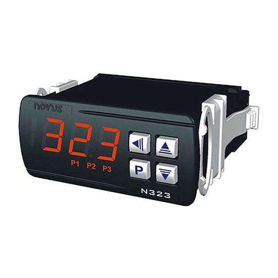
TEMPERATURE AND HUMIDITY
CONTROLLER
N323RHT (EI)
OPERATING MANUAL - V1.8x D
The N323RHT is a digital controller for relative humidity and temperature with three relay outputs
configurable independently for control, alarm or timer.
The RHT probe (3 m length) is provided along with the instrument.
SPECIFICATIONS
SENSOR INPUT: Humidity measurement
Range: 0 and 100 % (RH);
Accuracy: See Fig. 1;
Repeatability, Hysteresis and Linearity error: < 1 % RH;
Stability: < 1 % RH by year;
Response time: 4 seconds in range of 10 to 90 % in slow moving air.
SENSOR INPUT: Temperature
Accuracy: See Fig. 1;
Repeatability: ±0,1 °C;
Range: -20 and 100 °C;
Response time: up 30 seconds in slow moving air.
WARM-UP:
................................................................................. 15 minutes
MEASUREMENT RESOLUTION:
RH: .................................................................. 1 % in all range
T: ...................................................... 0,1º from –19,9 to 100,0º
Note: the equipment keeps its precision all over the range, despite the lack of display resolution in a part
of the range does not allow its visualization.
OUTPUT1: ........................................................... Relay SPDT; 1 HP 250 Vac / 1/3 HP 125 Vac (16 A Res.)
.................................................................................. Optional: Pulse, 5 Vcc, 25 mA max.
OUTPUT2: ...................................................................................................... Relay: 3 A / 250 Vca, SPST-NA
OUTPUT3: ...................................................................................................... Relay: 3 A / 250 Vca, SPST-NA
POWER SUPPLY:
Tension: ............................................ 100 to 240 Vca/cc ±10 %
Optional: ................................................................. 12 a 30 Vcc
Frequency:................................................................. 50~60 Hz
Consumption: .................................................................... 5 VA
Dimensions:
Width x Height x Depth: ............................................................ 75 x 33 x 75 mm
Weight: ........................................................................................................ 100 g
Panel cut-out: .................................................................................... 70 x 29 mm
Instrument operating environment: ..................................................................... 0 a 40 °C / 20 a 85 % RH
Probe operating environment: .................................................................................................... See Fig. 1
Case: Polycarbonate UL94 V-2
Protection: Box: IP42; Front panel: IP65
Suitable wiring: Up to 4.0 mm²
Interface RS485 with RTU MODBUS protocol (Optional)
Serial interface not isolated from input circuitry.
Input circuitry isolated from power supply, except in the 24 V powered model.
Measurement Accuracies and Sensor Operational Limits:
Relative Humidity Accuracy @ 25 °C
Sensor Operating Conditions
Fig. 1 - RH and temperatures accuracies
IMPORTANT
The sensor used in this controller may be damaged or lose calibration if exposed to atmospheres
contaminated with chemical agents. Chloride Acid, Nitride Acid, Sulphuric Acid or Ammonia. Acetone,
Ethanol and Propylene Glycol with high concentrations may cause reversible measurement drifts.
Acetone, Ethanol and Propylene Glycol may cause reversible measurement errors.
Corrections of eventual mistakes in sensors reading can be realized directly in the controller, at the
parameters 0fk e 0ft, in the configuration level.
Man 5001296
ELECTRICAL WIRING
The figure below indicates the connection to the sensor, power supply and controller output, as well as a
connection example.
RECOMMENDATIONS FOR INSTALLATION
The humidity sensor Conductors shall go through the system plant separately from the control and feeding
output conductors, if possible in grounded electrical ducts.
The controller feeding shall be preferably provided from a proper instrumentation network with a phase
different from the one used for the control output.
It is recommendable to use RC FILTERS (47 R and 100 nF, series) in contactor coils, solenoids, etc.
WORKING WITH THE CONTROLLER
Outputs for Control and Alarm – OUTPUT1 and OUTPUT2
The controller operates on the outputs OUTPUT1 and OUTPUT2 to lead the measured variable
(temperature or humidity) to the intended value, defined by the setpoints SP1, SP2.
The outputs operate as control outputs when they operate directly on the system load (resistance,
compressor, humidifier, etc.). They operate as alarm outputs when only notifying the operator about the
occurrence of any specific situation, defined by the user.
This two operation modes and they variations are presented below and can be defined on parameters
a(1 and a(2.
Reverse control action
0-
Activates the corresponding OUTPUT when the process variable is below the setpoint of that output.
Normally used for heating control.
Direct control action
1-
Temperature Accuracy
Activates the output whenever the process variable is above the setpoint for that output. The direct
action is used for refrigeration control.
Low Alarm
2-
Activates the output whenever the process variable is below the setpoint of that output.
High Alarm
3-
Activates the output whenever the process variable is above the setpoint for that output.
Low Alarm with Initial Blocking
4-
Identical to the Low Alarm, with the addition of the Initial Blocking feature explained in note below.
High Alarm with Initial Blocking
5-
Identical to the High Alarm, with the addition of the Initial Blocking feature explained in note below.
Inside Range Alarm (only for OUTPUT2)
6-
Activates the output when the process variable is within the interval defined below:
Outside Range Alarm (apenas para OUTPUT2).
7-
Activates the output when the process variable is outside the interval defined below:
Fig. 2 – N323RHT terminals – Relays share a common terminal - Standard Model
(SP1 – SP2) and (SP1 + SP2)
(SP1 – SP2) and (SP1 + SP2)
Inside the Range Alarm with Initial Blocking (only fot OUTPUT2)
8-
Identical to the Inside the Range Alarm with the addition of the Initial Blocking feature, describe in
note below.
Outside the Range Alarm with Initial Blocking (only for OUTPUT2)
9-
Identical to the Outside the Range Alarm with the addition of the Initial Blocking feature, describe in
note below.
The Initial Blocking impedes (blocks) the alarm from being switched on in the beginning of the
control process. The alarm will only be unblocked after the passage of the variable measured by a non-
alarm condition. This feature is useful when, for example, a minimum alarm is programmed in a heating
process. Without the blocking, the process would start with an enabled alarm until the control setpoint is
achieved.
Output Timing OUTPUT1 and OUTPUT2
The controller allows for the Output Timing programming of the output1 and output2, where the user can
establish three conditions: output tripping delay, temporary activation and sequential activation.
The timing is available only for outputs 1, 2 and 3 and is programmed by means of the "1t1", "2t1",
"1t2" and "2t2" parameters.
The figures below represent these functions; T1 and T2 can vary from 0 to 1999 seconds and their
combinations determine the timing mode. For normal operation of the alarms, without timing, program 0
(zero).
On the front panel, the controllers P1, P2 and P3 light when the respective outputs are activated. During
the delay, the respective signaler remains flashing.
TIMER FUNCTION
1t1 or 2t1
1t2 or 2t2
OUTPUT
Alarm
Output
Normal operation
0
0
Alarm Event
Alarm
Output
Delayed activation
0
1 to 1999 s
Alarm Event
Alarm
Temporary
Output
1 to 1999 s
0
activation
Alarm Event
Alarm
Sequential
Output
1 to 1999 s
1 to 1999 s
activation
Alarm Event
Table 1 – Timer alarm functions (outputs 1 and 2)
OUTPUT3
The output OUTPUT3 performs functions of a simple timer. It operates as definded in the paramaters T1
and T2, which establish, respectively, the activation duration of OUTPUT3 (Relay On) and activation
interval of OUTPUT3 (Relay Off).
OPERATION
The controller shall be set up by the user before using. This consideration consists in the definition of the
values for the various parameters that determine the equipment operation mode.
These set up parameters are organized in groups or Levels, called parameter levels.
Level
Function
0
Measurement
1
Setpoints and Time Adjustment
2
Configuration
3
Calibration
Upon power-up controller, the controller display shows for 1 second its firmware version. This information
is useful when consulting the factory.
Then, the temperature measured by the sensor is shown on the display. This is the parameter level 0 or
Temperature Measurement level.
For access to level 1 press
for 1 second till the "SP1" parameter appears. Release the
remain in this level. Press
again to access other parameters from this level. After the last parameter,
the controller goes back to the temperature measurement level.
To access level 2 of parameters, press
for 2 seconds until the "rkT" message is shown. Release the
key to remain in this level. Press
again to access other parameters from this level. After the last
parameter, the controller goes back to the temperature measurement level.
ACTION
T2
T1
T1
T2
T1
key to
Advertisement

Subscribe to Our Youtube Channel
Related Manuals for Novus N323RHT


Summary of Contents for Novus N323RHT
- Page 1 The alarm will only be unblocked after the passage of the variable measured by a non- The N323RHT is a digital controller for relative humidity and temperature with three relay outputs alarm condition. This feature is useful when, for example, a minimum alarm is programmed in a heating ELECTRICAL WIRING configurable independently for control, alarm or timer.
- Page 2 To change the parameters values, use the keys until the achievement of the desired values. Control OUTPUT 2 action: Shows the first two digits of the controller electronic serial number. 0 Reverse control action (heating or humidification); Notes: Each parameter, when accessed, alternately displays its symbol and its value. Action 2 Shows the three central digits of the controller electronic serial number.
Need help?
Do you have a question about the N323RHT and is the answer not in the manual?
Questions and answers