Advertisement
Quick Links
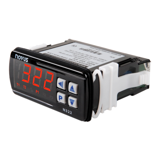
TEMPERATURE CONTROLLER
N322
OPERATING MANUAL - V1.8x F
The N322 is a 2-output digital electronic controller for heating and cooling applications.
It is available with NTC thermistor input sensor, Pt100, Pt1000 or J/K/T type
thermocouple. Sensor offset correction is provided. The 2 independent outputs can be
used as control or alarm. The features of a particular model (input sensor type, sensor
range, mains supply, etc.) are identified by the label placed on the controller body.
SPECIFICATIONS
INPUT SENSOR: The sensor is chosen by the user at the time of purchase and is
presented on the upper side of the equipment box. The options are:
• Thermistor NTC, 10 kΩ @ 25 °C; Range: –50 to 120 °C (–58 to 248 °F); Accuracy:
0.6 °C (1.1 °F);
Maximum error in the interchangeability of original NTC sensors: 0.75 °C (33.35 °F).
This error can be eliminated through the offset parameter of the equipment.
Note: For the NTC thermistor option, the sensor comes with the equipment. Its
operating range is limited to –30 to +105 °C (–222 to +221 °F). It has cable of 3 m in
length, 2 x 0.5 mm², and can be extended up to 200 meters.
• Pt100; Range: –50 to 300 °C (–58 to 572 °F); α= 0,00385; 3 wires;
Accuracy: 0.7 °C (1.3 °F); according to IEC-751 standards;
• Pt1000; Range: –200 to 530 °C (–328 to 986 ºF); α= 0,00385; 3 wires;
Accuracy: 0.7 °C (1.3 °F);
• Thermocouple type J; Range: 0 to 600 °C (32 to 1112 °F); Accuracy: 3 °C (5.4 °F);
• Thermocouple type K; Range –50 to 120 °C (–58 to 248 °F); Accuracy: 3 °C (5.4 °F);
• Thermocouple type T; Range: –50 to 120 °C (–58 to 248 °F); Accuracy: 3 °C (5.4 °F);
Thermocouples according to IEC-584 standards.
WARM-UP: ..................................................................................................... 15 minutes
MEASUREMENT RESOLUTION:
From –19.9 to 199.9 º with NTC, Pt100 and Pt1000: .................................................... 0.1
Elsewhere: .................................................................................................................. 1
Note: The equipment keeps its precision all over the range, despite the lack of display
resolution in a part of the range does not allow its visualization.
OUTPUT1: .................... Relay SPDT; 1 HP 250 Vac / 1/3 HP 125 Vac (16 A Resistive)
OUTPUT2: ........................................................................... Relay: 3 A / 250 Vac, SPST
POWER SUPPLY: ....................... 100~240 Vac (± 10 %) or 24 Vdc/ac (12~30 Vdc/ac)
................................................. Mains frequency: 50~60 Hz. Power consumption: 5 VA
Caution: check the power supply specification before energizing the controller.
DIMENSIONS: ................................................ Width x Height x Depth: 74 x 32 x 75 mm
....................................................................... Panel cut-out: 70 x 29 mm; Weight: 100 g
ENVIRONMENT: ............................... Operating temperature: 0 to 40 °C (32 to 104 °F)
............................................................ Storage temperature: -20 to 60 °C (-4 to 140 °F)
................................................................ Relative humidity: 20 to 85 % non-condensing
CASE: ..................... Polycarbonate UL94 V-2; Protection: Front panel: IP65, Box: IP42
......................................................................................... Suitable wiring: Up to 4.0 mm²
RS-485 digital communication; RTU MODBUS protocol (optional)
Serial interface not isolated from input circuitry.
Serial interface isolated from input circuitry, except in 24 V powered model.
ELECTRICAL WIRING
It is important to follow the recommendations below:
Signal wires should be installed in grounded conduits and away from power or
•
contactor wires.
The instrument should have its own power supply wires that should not be shared
•
with electrical motors, coils, contactors, etc.
Installing RC filters (47 R and 100 nF, series combination) is strongly recommended
•
at contactor coils or any other inductors.
Fig. 1 below shows the controller connections to sensor, mains and outputs.
Man 5001230
Pt100 with 3 conductors: Terminals 11, 12 and 13 must have the same wire
resistance for proper cable length compensation. For 2 wire Pt100, short circuit
terminals 11 and 13.
OPERATION
The controller requires the internal parameters to be configured according to the
intended use for the instrument. The parameters are organized in 4 groups or levels:
Level
0
1
2
3
Upon power-up, the N322 display shows for 1 second its firmware version. This
information is useful when consulting the factory.
Then, the temperature measured by the sensor is shown on the display. This is the
parameter level 0 (temperature measurement level).
To access level 1, press
for 1 second until the "SP1" message shows up. Pressing
again, the "SP2" parameter is presented. To go back to level 0, press
more.
To access level 2 of parameters, press
shown. Release the
key to remain in this level. Each new pressing on the
will advance to the next parameter in the level. At the end of the level, the controller
returns to the first level (0). Use the
Notes: 1
A parameter configuration is saved when the
advance to the next parameter in the cycle. The configuration is stored in a
non-volatile memory, retaining its value when the controller is de-
energized.
2
If no keyboard activity is detected for over 20 seconds, the controller saves
the current parameter value and returns to the measurement level.
Level 1 –Setpoint Adjustment
In this level only the Setpoint (SP1 and SP2) parameters are available, alternating the
names with their respective values. Adjust the desired temperature for each setpoint
clicking on the
and
keys.
Temperature adjustment for control OUTPUT 1. SP1 value is limited to
SP1
the values programmed in SPL and SPk in the programming level
Set Point 1
(Parameter configuration, level 2).
Temperature adjustment for control OUTPUT 2. SP2 value is limited to
SP2
the values programmed in SPL and SPk
Set Point 2
Fig. 1 – N322 terminals
Function
Temperature measurement
Setpoint Adjustment
Configuration
Calibration
once
for 2 seconds until the "uNT" message is
key
and
keys to alter a parameter value.
key is pressed to
Level 2 – Configuration - Parameters configuration Level
Contains the configuration parameters to be defined by the user, according to the
system's requirements. Use
and
keys to set the value. The display alternates
the parameter name and respective value.
Temperature Unit - Selects display indication for degrees Celsius or
Unt
Fahrenheit.
0 – Temperature in degrees Celsius
1 - Temperature in degrees Fahrenheit
Input Type - Selects the input sensor type to be connected to the
typ
controller. Available only for thermocouple models, allowing selection of
types J, K and T.
0 - Thermocouple type J
1 - Thermocouple type K
2 - Thermocouple type T
Sensor Offset - Offset value to be added to the measured temperature
ofs
to compensate sensor error.
SP Low Limit - Lower range for SP1 and SP2. SPL must be
spl
programmed with a lower value than spK.
SP High Limit - Upper range for SP1 and SP2. SPx must be greater
spK
than spl.
OUTPUT 1 Hysteresis: defines the differential range between the
ky1
temperature value at which the OUTPUT 1 is turned on and the value at
which it is turned off. In degrees.
OUTPUT 2 Hysteresis: defines the differential range between the
ky2
temperature value at which the OUTPUT 2 is turned on and the value at
which it is turned off. In degrees.
Control action for OUTPUT 1 :
Ac1
Reverse: For heating applications. Outputs turn on when
0
temperature is lower than SP.
Direct: For cooling applications. Output turns on when
1
temperature is above SP.
Action 2 - Control OUTPUT 2 action or Alarm functions:
Ac2
Reverse control action (heating).
0
Direct control action (cooling).
1
Low (minimum) temperature alarm.
2
High (maximum) temperature alarm.
3
Alarm for temperature inside the range
4
Alarm for temperature outside the range.
5
Low temperature alarm with initial blocking.
6
High temperature alarm with initial blocking.
7
Inside range alarm with initial blocking.
8
Outside range alarm with initial blocking.
9
The section Working with the Controller describes how these
functions work.
Advertisement

Related Manuals for Novus N322


Summary of Contents for Novus N322
- Page 1 Fig. 1 below shows the controller connections to sensor, mains and outputs. Man 5001230 Temperature Unit - Selects display indication for degrees Celsius or The N322 is a 2-output digital electronic controller for heating and cooling applications. Fahrenheit. It is available with NTC thermistor input sensor, Pt100, Pt1000 or J/K/T type 0 –...
- Page 2 Parameter for definition of a new password. Since it is located in the calibration Control - Associates Setpoints and Outputs. Calibration High - Gain calibration. It adjusts the upper measurement level, can only be changed by a user that knows the current password. Valid range of the sensor.
Need help?
Do you have a question about the N322 and is the answer not in the manual?
Questions and answers