Table of Contents
Advertisement
Quick Links
Advertisement
Table of Contents

Subscribe to Our Youtube Channel
Related Manuals for BLAUBERG Ventilatoren inWave 100


Summary of Contents for BLAUBERG Ventilatoren inWave 100
- Page 1 ИНСТРУКЦИЯ Blauberg inWave 100/125...
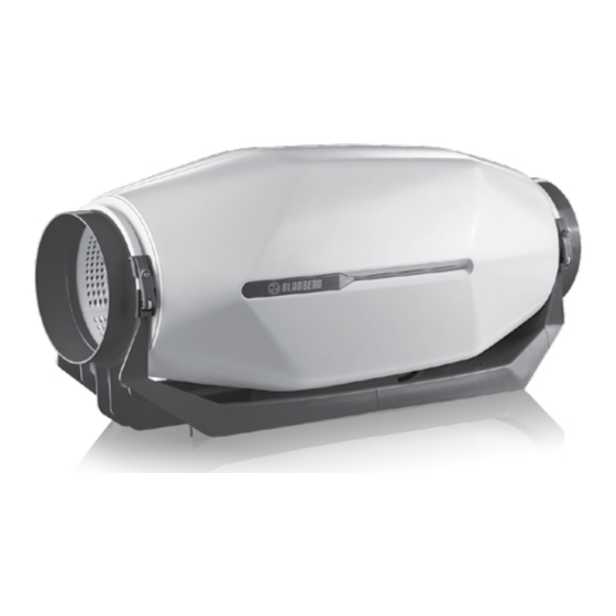
- Page 2 INLINE MIXED-FLOW FANS inWave inWave EC User’s manual...
-
Page 3: Table Of Contents
CONTENTS Delivery set ................................................9 Brief description ..............................................9 Operation guidelines ............................................9 Designation key ..............................................10 Technical data ............................................... 11 Mounting ................................................. 12 Electronics operation algorithm ....................................... 18 Technical maintenance ........................................... 21 Troubleshooting ..............................................22 Storage and transportation regulations ....................................23 Manufacturer’s warranty .......................................... - Page 4 This unit is not intended for use by persons (including children) with reduced physical, sensory or mental capabilities, or lack of experience and knowledge, unless they have been given supervision or instruction concerning use of the unit by a person responsible for their safety.
- Page 5 Connection to the mains must be made through a disconnecting device, which is integrated into the fixed wiring system in accordance with the wiring rules for design of electrical units, and has a contact separation in all poles that allows for full disconnection under overvoltage category III conditions.
- Page 7 All operations described in this manual must be performed by qualified personnel only, properly trained and qualified to install, make electrical connections and maintain ventilation units. Do not attempt to install the product, connect it to the mains, or perform maintenance yourself. This is unsafe and impossible without special knowledge.
- Page 8 of any foreign objects that can damage the impeller blades. While mounting the unit, avoid compression of the casing! Deformation of the casing may result in motor jam and excessive noise. Misuse of the unit and any unauthorised modifications are not allowed.
- Page 9 order to incorporate the latest technological developments. Never touch the unit with wet or damp hands. Never touch the unit when barefoot. BEFORE INSTALLING ADDITIONAL EXTERNAL DEVICES, READ THE RELEVANT USER MANUALS. THE PRODUCT MUST BE DISPOSED SEPARATELY AT THE END OF ITS SERVICE LIFE. DO NOT DISPOSE THE UNIT AS UNSORTED DOMESTIC WASTE...
- Page 10 inWave (EC) 100/125 (spigot ø100 mm) inWave (EC) 100/125 (spigot ø125 mm) inWave (EC) 150 (spigot ø150 mm) inWave (EC) 160 (spigot ø150 mm with a rubber seal) Ø D inWave (EC) 100/125 inWave (EC) 150...
-
Page 11: Delivery Set
DELIVERY SET Fan – 1 pc. Screws and dowels – 4 pcs. User’s manual – 1 pc. Packing box – 1 pc. Rubber seal (for the inWave 150/160 model) – 2 pcs. BRIEF DESCRIPTION The product described herein is a mixed-flow inline fan for supply or extract ventilation of premises. The fan is connected to the ø... -
Page 13: Designation Key
DESIGNATION KEY inWave EC 150 US Options: T: timer; G1: speed controller with an electronic thermostat and an outdoor temperature sensor fixed on a 4 m cable. Equipped with a power cord with a mains plug. Temperature-based operation logic; GT1: speed controller with an electronic thermostat and external temperature sensor fixed on a 4 m cable. -
Page 14: Technical Data
TECHNICAL DATA To comply with the ErP 2018 regulation, a local demand controller and speed controller must be used. -
Page 15: Mounting
MOUNTING The fan is suitable both for horizontal or vertical mounting on the floor, on the wall or on the ceiling. The fan can be installed independently or as part of a set with parallel or in-series connection. min 1 m... - Page 16 The diameter of the spigots in the Stream 100/125 model can be changed using adapters, and in the Stream 150/160 model using the rubber seal. On outlet (discharge) spigot side it is necessary to install: • in case of horizontal installation – a duct with a length of at least 1 m; •...
- Page 17 3 1 4 1 3 3...
- Page 19 The fan wiring diagrams inWave inWave ...T High High High...
- Page 20 Designations on diagrams: L – line; N – neutral; LT – external switch terminal; L1 – minimum speed terminal; High – maximum speed terminal; Med – medium speed terminal; Low – minimum speed terminal; QF – automatic circuit breaker; S – external speed controller; ST – external switch (for example, a light switch); X –...
- Page 21 inWave ...T 2 min 30 min inWave EC...
-
Page 22: Electronics Operation Algorithm
ELECTRONICS OPERATION ALGORITHM inWave (EC)...FR1 inWave (EC)...G1,GT1,GS1 Thermostat control knob Speed control knob Speed control knob inWave The fan speed without options can be controlled by voltage, as well as by thyristor controllers. A speed controller can be purchased separately. Warning! When adjusting the voltage, ensure that there is no unusual noise or vibration at reduced motor speed. - Page 23 The inWave ...T fan activates upon control voltage application to the LT input terminal by the external switch (e.g. indoor light switch). After the control voltage is off, the fan continues to operate within the set time period adjustable from 2 to 30 min by the timer.
- Page 25 inWave ...GS1: the fan switches to the maximum speed as the room air temperature exceeds the set point. As the air temperature drops 2 °C below the set point or if the initial temperature is below the set point, the fan operates with the set speed.
-
Page 26: Technical Maintenance
TECHNICAL MAINTENANCE The fan surfaces must be regularly cleaned (once in 6 months) from dirt and dust. Disconnect the fan from power mains prior to any maintenance operations. To clean the fan, use a soft cloth or a brush wetted in a mild detergent solution. Do not allow water or liquid come into contact with electric components. -
Page 27: Troubleshooting
TROUBLESHOOTING Problem Possible reasons Troubleshooting Make sure the power supply line When the unit is connected to power No power supply. is connected correctly, otherwise troubleshoot a connection error. mains, the fan does not rotate and does not respond to any controls. Internal connection fault. -
Page 28: Storage And Transportation Regulations
STORAGE AND TRANSPORTATION REGULATIONS • Store the unit in the manufacturer’s original packaging box in a dry closed ventilated premise with temperature range from +5 ˚С to +40 ˚С and relative humidity up to 70 %. • Storage environment must not contain aggressive vapors and chemical mixtures provoking corrosion, insulation, and sealing deformation. -
Page 29: Manufacturer's Warranty
MANUFACTURER’S WARRANTY The product is in compliance with EU norms and standards on low voltage guidelines and electromagnetic compatibility. We hereby declare that the product complies with the provisions of Electromagnetic Compatibility (EMC) Directive 2014/30/ EU of the European Parliament and of the Council, Low Voltage Directive (LVD) 2014/35/EU of the European Parliament and of the Council and CE-marking Council Directive 93/68/EEC. - Page 31 • Redesign or engineering changes to the unit. • Replacement and use of any assemblies, parts and components not approved by the manufacturer. • Unit misuse. • Violation of the unit installation regulations by the user. • Violation of the unit control regulations by the user. •...
- Page 33 Quality Inspector’s Stamp Seller (name and stamp of the seller) Manufacture Date Purchase Date...
- Page 34 inWave________________________________ www.blaubergventilatoren.de B238EN-03...
- Page 35 СМОТРИТЕ ТАКЖЕ Канальные Реверсивные Потолочные Вытяжные вентиляторы вентиляторы вентиляторы вентиляторы Установка канальных Автоматические Бытовые рекуператоры вентиляторов выключатели...
Need help?
Do you have a question about the inWave 100 and is the answer not in the manual?
Questions and answers