Welbilt CONVOTHERM OES 10.10 mini Installation Manual
Combi oven
Hide thumbs
Also See for CONVOTHERM OES 10.10 mini:
- User manual (177 pages) ,
- User manual (148 pages) ,
- Operating manual (170 pages)
Table of Contents
Advertisement
Quick Links
Advertisement
Table of Contents

Related Manuals for Welbilt CONVOTHERM OES 10.10 mini


Summary of Contents for Welbilt CONVOTHERM OES 10.10 mini
- Page 1 Combi Oven OES 10.10 mini Installation manual UL, USA - Original, ENG...
- Page 3 FOR THE INSTALLER, OPERATOR, RESPONSIBLE OWNER FOR YOUR SAFETY Do not store or use gasoline or other flammable vapors or liquids in the vicinity of this or any other unit. WARNING Improper installation, adjustment, alteration, service or maintenance can cause property damage, injury and death. Read the installation, operating and maintenance instructions thoroughly before installing or servicing this equipment.
-
Page 5: Table Of Contents
Table of Contents Table of Contents General Environmental Protection Identifying Your Combi Oven Customer Documentation Structure Safety Information That Must Be Read without Exception About This Installation Manual Configuration and Functions The Combi Oven's Configuration and Functions Control Panel Layout and Functions For Your Safety Basic Safety Instructions Your Combi Oven's Intended Use... - Page 6 Table of Contents Placing into operation Working Safely When Putting the Unit Into Operation Procedure for Placing the Unit into Operation Removing from Service and Disposal Working Safely When Removing the Unit from Service Removing from Service and Disposal Technical Data and Connection Drawing Technical data Connection drawing Installation Manual...
-
Page 7: General
1 General 1 General Purpose of this section This section provides information on how to identify your combi oven and how to use this manual. 1.1 Environmental Protection Policy statement Our customers' expectations, the legal regulations and standards we have to follow, and our compa‐ ny's reputation are what drives the quality and service behind all our products. -
Page 8: Identifying Your Combi Oven
1 General 1.2 Identifying Your Combi Oven Nameplate location The nameplate is found on the left side of the combi oven. Nameplate layout and structure The nameplate makes it easy to identify your unit. The nameplate has the following layout: Designation Unit name Combi Oven Trade name... -
Page 9: Customer Documentation Structure
1 General 1.3 Customer Documentation Structure Customer Documentation Structure The following table outlines how the customer documentation is structured: Subject Description Please refer to Transportation Transporting the combi oven Installation manual Setup Setup options (intended for trained ■ Correctly setting up the combi oven qualified personnel;... -
Page 10: Safety Information That Must Be Read Without Exception
1 General 1.4 Safety Information That Must Be Read without Exception Safety information found in the documentation for the customer The most important safety information for the combi oven is essentially found in the installation manual and operating manual. The installation manual provides safety information for the transportation, setup, installation, placing- into-operation, and removal-from-service tasks it describes. -
Page 11: About This Installation Manual
1 General 1.5 About This Installation Manual Purpose The purpose of this installation manual is to provide everyone working with/on the combi oven with the information they will need to transport, set up, install, and place the unit into operation safely and cor‐ rectly. - Page 12 1 General Decimal mark used In order to ensure that all numbers can be properly understood internationally, a decimal point is al‐ ways used. Installation Manual...
-
Page 13: Configuration And Functions
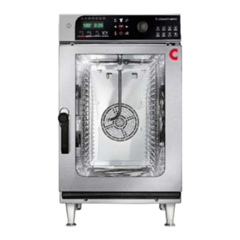
2 Configuration and Functions 2 Configuration and Functions Purpose of this section This section describes the combi oven's configuration and explains its functions. 2.1 The Combi Oven's Configuration and Functions Combi oven's configuration The following figure illustrates the combi oven: The combi oven's parts and what they do Following is a description of what the combi oven's parts do: Designation Function... - Page 14 2 Configuration and Functions Designation Function Connection angle brack‐ Used to cover the connection area Opening between the Used for ventilation purposes front feet Oven cavity Is where food is placed while it is being cooked Height-adjustable feet Used to set up and level the unit Nameplate Used to identify the combi oven Material...
-
Page 15: Control Panel Layout And Functions
2 Configuration and Functions 2.2 Control Panel Layout and Functions Control panel layout The figure below shows the control panel: Control panel parts Following is an explanation of what the control panel's parts do: Designation Function Main switch Used to turn the combi oven on and off Display and program se‐... -
Page 16: For Your Safety
3 For Your Safety 3 For Your Safety Purpose of this section The purpose of this section is to provide you with all the information you will need in order to safely work with/on the combi oven without putting yourself and others at risk. Read this section very carefully! 3.1 ... - Page 17 3 For Your Safety For more information... Related subjects Your Combi Oven's Intended Use Warning Labels on the Combi Oven Hazards and Safety Measures When Moving the Unit Hazards and Safety Measures During Setup Hazards and Safety Measures During Installation Hazards and Safety Measures When Putting the Unit into Operation Hazards and Safety Measures When Removing the Unit from Service Safety Devices...
-
Page 18: Your Combi Oven's Intended Use
3 For Your Safety 3.2 Your Combi Oven's Intended Use The combi oven's intended use The combi oven has been designed and built exclusively for cooking a variety of food in standard- ■ size bakeware (steam table pans, sheet pans, etc.). Steam, convection, and combi-steam (steam superheated without pressure) are used for this purpose. - Page 19 3 For Your Safety Requirements concerning the combi oven's surroundings Required combi oven surroundings Ambient temperature between 40°F and 95°F ■ No toxic or potentially explosive atmospheres ■ Do not use or store gasoline or other flammable vapors, gases, or liquids in the vicinity of a combi ■...
-
Page 20: Warning Labels On The Combi Oven
3 For Your Safety 3.3 Warning Labels on the Combi Oven Warning label locations The warning labels are found at the following locations on the combi oven: Warning labels on unit door The following warning labels (1) are located on the unit door: Warning Description Hot food, hot bakeware, and hot liquid warning... - Page 21 3 For Your Safety Warning Description CAUTION Surface(s) and Handle(s) may be hot. ATTENTION Surface(s) et poignée(s) chaudes INTERIOR CLEANING INSTRUCTION WARNING To clean the cooking compartment see the operator's manual for complete instructions. ConvoClean cleaning solutions followed by the ConvoRinse solution.
-
Page 22: Hazards And Safety Measures When Moving The Unit
3 For Your Safety 3.4 Hazards and Safety Measures When Moving the Unit Safety hazard: moving heavy loads When moving or transporting the unit, keep the following hazards in mind and take the actions re‐ quired in order to eliminate and/or minimize these hazards: Risk / hazard Where and in which situa‐... -
Page 23: Hazards And Safety Measures During Setup
3 For Your Safety 3.5 Hazards and Safety Measures During Setup Safety hazard: moving heavy loads When setting up the unit, keep the following hazards in mind and take the actions required in order to eliminate and/or minimize these hazards: Risk / hazard Where and in which situa‐... - Page 24 3 For Your Safety Safety hazard: mechanical unit components When setting up the unit, keep the following hazards in mind and take the actions required in order to eliminate and/or minimize these hazards: Risk / hazard Where and in which situa‐ What to do Safety device tions will the risk/hazard ex‐...
-
Page 25: Hazards And Safety Measures During Installation
3 For Your Safety 3.6 Hazards and Safety Measures During Installation Safety hazard: electricity When installing the unit, keep the following hazards in mind and take the actions required in order to eliminate and/or minimize these hazards: Risk / hazard Where and in which situa‐... - Page 26 3 For Your Safety Safety hazard: mechanical unit components When installing the unit, keep the following hazards in mind and take the actions required in order to eliminate and/or minimize these hazards: Risk / hazard Where and in which situa‐ What to do Safety device tions will the risk/hazard ex‐...
-
Page 27: Hazards And Safety Measures When Putting The Unit Into Operation
3 For Your Safety 3.7 Hazards and Safety Measures When Putting the Unit into Operation Safety hazard: electricity When putting the unit into operation, keep the following hazards in mind and take the actions required in order to eliminate and/or minimize these hazards: Risk / hazard Where and in which situa‐... - Page 28 3 For Your Safety Safety hazard: moving units on bases with casters Risk / hazard Where and in which situa‐ What to do Safety device tions will the risk/hazard ex‐ ist? All the risks and haz‐ When units are being moved Before moving the unit Retaining ele‐...
- Page 29 3 For Your Safety Additional safety hazards when placing the unit into operation When putting the unit into operation, make sure to read and understand the following topics in the 'For Your Safety' section of the user manual in addition to the safety information in this section. Hazards and Safety Measures During Operation ■...
-
Page 30: Hazards And Safety Measures When Removing The Unit From Service
3 For Your Safety 3.8 Hazards and Safety Measures When Removing the Unit from Service Safety hazard: electricity When removing the unit from service, keep the following hazards in mind and take the actions re‐ quired in order to eliminate and/or minimize these hazards: Risk / hazard Where and in which situa‐... - Page 31 3 For Your Safety Safety hazard: moving units on bases with casters Risk / hazard Where and in which situa‐ What to do Safety device tions will the risk/hazard ex‐ ist? All the risks and haz‐ When units are being moved De-energize the unit be‐...
- Page 32 3 For Your Safety Safety hazard: mechanical unit components When removing the unit from service, keep the following hazards in mind and take the actions re‐ quired in order to eliminate and/or minimize these hazards: Risk / hazard Where and in which situa‐ What to do Safety device tions will the risk/hazard ex‐...
-
Page 33: Safety Devices
3 For Your Safety 3.9 Safety Devices Meaning The combi oven features a series of safety devices and guards that protect the user from a variety of hazards. All safety devices and guards must be present, fully functional, and locked properly without exception when the combi oven is being used. - Page 34 3 For Your Safety Safety device Function Check Unit door cracked-open Prevents steam coming out With the combi oven at a low position from scalding the operator's temperature, check the door face and hands positions as described in 'Safely Opening and Closing the Unit Door' in the operating manual Suction panel inside...
-
Page 35: Staff And Work Area Requirements
3 For Your Safety 3.10 Staff and Work Area Requirements Staff requirements The table below specifies the qualifications needed for each role. Provided that they have the required qualifications, a single person can take over more than one role if necessary. Role Required qualifications Tasks... - Page 36 3 For Your Safety Work areas during installation and placement into operation During installation and placement into operation, the work area for staff will be the entire area occu‐ pied by the unit and its surroundings. Installation Manual...
-
Page 37: Personal Protective Equipment
3 For Your Safety 3.11 Personal protective equipment Transportation and setup Wear the following personal protective equipment when transporting and setting up the combi oven: Task Tools used Personal Protective Equipment Transporting the unit within the fa‐ Carrying straps Protective gloves ■... -
Page 38: Transportation
4 Transportation 4 Transportation Purpose of this section This section provides information on how to transport your unit. This section is intended for the user, as well as for installers and authorized customer service compa‐ nies. 4.1 Working Safely During Transportation For Your Safety Before starting your work, read and understand the hazards described in Hazards and Safety Meas‐... -
Page 39: Transporting The Unit To The Installation Location
4 Transportation 4.2 Transporting the unit to the installation location Required space during transportation Make sure that the transportation route you will be following has enough space to accommodate the unit's entire width and height at all times. The following table provides the minimum door width and height required in order to be able to get the combi oven to its intended installation location. -
Page 40: Setup
5 Setup 5 Setup Purpose of this section This section provides information on how to set up your unit. This section is intended for the user, as well as for installers and authorized customer service compa‐ nies. 5.1 Working Safely During Setup For Your Safety Before starting your work, read and understand the hazards described in Hazards and Safety Meas‐... - Page 41 5 Setup Unsuitable supporting surfaces Crush hazard posed by the unit falling down or toppling over Body parts may be crushed if the unit falls down or topples over. Make sure never to place the unit on an unsuitable supporting surface. Installation Manual...
-
Page 42: Adjacent Systems
5 Setup 5.2 Adjacent Systems Handling exhaust air During operation, the combi oven will produce heat and moisture, most of which will escape upwards into the ambient air in the form of hot steam coming through the air vent. Do not connect any lines or ducts directly to the combi oven's air vent! The manufacturer recommends removing this exhaust air from the combi oven's working area with a range hood or ventilated ceiling. -
Page 43: Installation Location Requirements
5 Setup 5.3 Installation location requirements Meaning This section provides information on how to choose a suitable installation location for the unit. Careful‐ ly check the intended installation location to make sure it is adequate before bringing the unit there and starting with the installation! Rules for safely setting up the unit In order to prevent hazards that may be posed by the installation location and by the unit's surround‐... - Page 44 5 Setup The following table lists the various weights that make up the unit's weight during operation: Weight Without base Unit weight when empty [lbs] 155 Maximum permissible loading weight [lbs] 66 Maximum weight of cleaning agents [lbs] 44 Unit weight during operation without base [lbs] 265 Base Equipment stand weight...
- Page 45 5 Setup Dimen‐ Meaning Required space sion Minimum required space for the unit width when the door is [in] 24.9 opened 90° Minimum required space for the unit width when the door is [in] 41.5 opened 180° Minimum required space for the unit depth (including open [in] 51.8 door)
-
Page 46: Unpacking
5 Setup 5.4 Unpacking Checking the tilt indicator Before unpacking the unit, check the tilt indicator on the packaging. The following table shows the various possible tilt indicator conditions: Indicator Meaning Procedure Silver dot: Unpack the unit ■ The unit has been transported prop‐ Compare the tilt indicator's number ■... - Page 47 5 Setup Included equipment and parts The following should be included with the unit: One combi oven ■ One left-hand side rack ■ One right-hand side rack ■ One installation manual ■ One operating manual ■ Installation Manual...
-
Page 48: Removing The Unit From The Pallet
5 Setup 5.5 Removing the unit from the pallet Removing the unit from the pallet using the carrying straps To find out how much your unit weighs, consult the Technical Data on page 71 section. Follow the steps below when lifting the unit off from the pallet: Step Procedure Figure... -
Page 49: Setting Up The Unit On A Work Table
5 Setup 5.6 Setting up the unit on a work table Rules for safely setting up the unit Observe the following rules in order to ensure that the unit will have the required stability: It must be possible to set up the work table at the installation location in such a way that it will not ■... -
Page 50: Setting Up The Unit On A Stand
5 Setup 5.7 Setting Up the Unit on a Stand Rules for safely setting up the unit Observe the following rules in order to ensure that the unit will have the required stability: The unit's equipment stand must be secured in such a way that it cannot topple over if it is subjec‐ ■... - Page 51 5 Setup Step Procedure Figure Use the enclosed screws (5) to screw the unit onto the equipment stand from below. Position the device with the stand and use the height- adjustable feet to level the stand. Use a spirit level to make sure that the unit is properly leveled.
-
Page 52: Installation
6 Installation 6 Installation Purpose of this section This section goes over how to connect your combi oven. 6.1 Electrical installation Purpose of this section This section goes over how to electrically install the unit. 6.1.1 Working Safely When Installing the Electrical Installation For Your Safety Before starting your work, read and understand the hazards described in Hazards and Safety Meas‐... -
Page 53: Planning The Electrical Installation
6 Installation 6.1.2 Planning the Electrical Installation Meaning It is crucial for the unit's electrical system to be properly installed in order for the unit to run safely and without any problems. All the rules and specifications specified in this section, as well as the proce‐ dures described, must be followed to the letter. -
Page 54: Performing The Electrical Installation
6 Installation 6.1.3 Performing the Electrical Installation Prerequisites Check whether the following prerequisite is met: The unit's connection point has been de-energized and locked and tagged out. ■ Checking the rating data and electrical connections Follow the steps below to check the connection to the electrical system and the electrical connections: Step Procedure Figure... -
Page 55: Water Connection
6 Installation 6.2 Water connection Purpose of this section This section goes over how to set up the water connection. 6.2.1 Working Safely When Setting Up the Water Connection For Your Safety Before starting your work, read and understand the hazards described in Hazards and Safety Meas‐ ures During Installation on page 25. -
Page 56: Water Supply
6 Installation 6.2.2 Water supply Rules for safely installing the water connection In order to prevent hazards related to an improperly installed water connection, make sure to observe the following rules: In the case of units placed on a base with casters, the water connection must use a flexible hose. ■... - Page 57 6 Installation Shut-off device with mesh Water valve strainer Appropriate backflow prevent‐ The unit must be installed with an appropriate backflow pre‐ venter in order to comply with all applicable federal, state, and local laws and regulations. Installing the water supply connection Follow the steps below to set up the water supply for your combi oven: Step Procedure...
-
Page 58: Water Drain
6 Installation 6.2.3 Water drain Rules for safely installing the drain connection In order to prevent hazards related to an improperly installed drain connection, make sure to observe the following rules: The drain pipes must be made of PVC or copper and must be able to withstand a temperature of ■... - Page 59 6 Installation Installing the water drain Follow the steps below to set up the water drain for your combi oven: Step Procedure Connect the unit as shown in the connection diagram. Installation Manual...
-
Page 60: Convoclean System Installation
6 Installation 6.3 ConvoClean System Installation Purpose of this section This section goes over how to set up the fully automatic ConvoClean oven cleaning system. 6.3.1 Working Safely When Installing the ConvoClean System For Your Safety Before starting your work, read and understand the hazards described in Hazards and Safety Meas‐ ures During Installation on page 25. -
Page 61: Components Of Fully Automatic Oven Cleaning System
6 Installation 6.3.2 Components of Fully Automatic Oven Cleaning System Cleaning agents and rinse aid Only use the products specified here in order to clean the combi oven. NOTICE! The warranty will be void if there is any damage that can be traced back to the use of incor‐ rect cleaning agents. -
Page 62: Connecting The Fully Automatic Cleaning System
6 Installation 6.3.3 Connecting the Fully Automatic Cleaning System Rules for safely connecting the fully automatic oven cleaning system Getting the ConvoClean and ConvoCare connections mixed up may pose a risk of injury or illness when food cooked afterwards is eaten. In order to prevent this risk, make sure to observe the following rules: When connecting ConvoClean forte and ConvoCare, make absolutely sure that the hoses are con‐... -
Page 63: Placing Into Operation
7 Placing into operation 7 Placing into operation Purpose of this section This section goes over how to put your combi oven into operation, remove it from service, and dispose of it properly. 7.1 Working Safely When Putting the Unit Into Operation For your safety when placing the combi oven into operation Before starting your work, read and understand the hazards described in Hazards and Safety Meas‐... - Page 64 7 Placing into operation Additional rules for safely running the unit on a moving base In order to avoid hazards, follow the rules below when running units on a base with casters: The retaining element used to limit how much the base can move with the unit must be attached at ■...
- Page 65 7 Placing into operation Contact with cleaning agents Risk of chemical burns and skin, eye, and respiratory tract irritation The ConvoClean new cleaning agent and the ConvoCare rinse aid will cause skin, eye, and respiratory tract irritation upon direct contact. The ConvoClean forte cleaning agent will result in chemical burns to the skin, eyes, and respiratory tract upon direct contact.
-
Page 66: Procedure For Placing The Unit Into Operation
7 Placing into operation 7.2 Procedure for Placing the Unit into Operation Meaning This section is intended to provide commissioning staff with an overview of the prerequisites that must be met before placing the combi oven into operation, as well as with information on how to place it into operation. - Page 67 7 Placing into operation Step Procedure For more information... Check the following: Is the oven light on? ■ Is the fan running? ■ Are there any leaks in the wastewater and supply wa‐ ■ ter systems? Is the temperature increasing inside the oven cavity? ■...
-
Page 68: Removing From Service And Disposal
8 Removing from Service and Disposal 8 Removing from Service and Disposal Purpose of this section This section goes over how to remove your combi oven from service and dispose of it properly. 8.1 Working Safely When Removing the Unit from Service For your safety when removing the combi oven from service Before starting your work, read and understand the hazards described in Hazards and Safety Meas‐... - Page 69 8 Removing from Service and Disposal Unsuitable supporting surfaces Crush hazard posed by the unit falling down or toppling over Body parts may be crushed if the unit falls down or topples over. Make sure never to place the unit on an unsuitable supporting surface. Contact with cleaning agents Risk of chemical burns and skin, eye, and respiratory tract irritation The ConvoClean new cleaning agent and the ConvoCare rinse aid will cause skin, eye, and...
-
Page 70: Removing From Service And Disposal
8 Removing from Service and Disposal 8.2 Removing from Service and Disposal Prerequisites Check the following before removing the unit from service: The unit has been de-energized. ■ The water supply has been shut off. ■ Removing from service To remove your combi oven from service, undo all setup and installation work step-by-step in opposite order (please refer to the 'Installation on page 52', 'Transportation on page 38', and 'Setup on page 40' sections). -
Page 71: Technical Data And Connection Drawing
9 Technical Data and Connection Drawing 9 Technical Data and Connection Drawing 9.1 Technical data Dimensions and weights The following table lists the various dimensions and weights: Dimensions and weights Width With packaging [in] 22.8 Without packaging [in] 20.3 Depth With packaging [in] 35.8 Without packaging... - Page 72 9 Technical Data and Connection Drawing Electrical ratings The following table lists the various electrical rating specifications: Electrical ratings 3~ 208V-240V 60Hz (3/PE) Rated power consumption [kW] 8.50 Hot air output (RHK rated output) [kW] 8.16 Motor output [kW] 0.25 Rated current 23.6 Supplied with a 4 conductor 6 foot long cord...
- Page 73 9 Technical Data and Connection Drawing Water quality The following table lists water quality specifications: Water hardness for water injection Water quality Drinking water Soft water Hardness [ppm] 70 - 125 (4 - 7 gpg) TDS (total dissolved solids) [ppm] 70 - 125 Total alkalinity [ppm]...
-
Page 74: Connection Drawing
9 Technical Data and Connection Drawing 9.2 Connection drawing OES 10.10 mini dimensions and connection points The following table shows the various dimensions and connection points: View Side view 16.9 22.4 20.3 30.6 View from above with wall clearances Connections at the bottom of the unit G M F C B A E D 19.2 20.4... - Page 76 Item no. Order No. Additional technical documentation can be found in the download center at : www.convotherm.com Welbilt off ers fully-integrated kitchen systems and our products are ® backed by KitchenCare aftermarket parts and service. Welbilt’s portfolio of award-winning brands includes Cleveland™, Convotherm , Delfi...
- Page 77 This product conforms to the ventless LISTED COOKING APPLIANCE operation recommendations set forth E360598 by NFPA96 using EPA202 test method. Welbilt Inc. Phone 1-800-338-2204 www.convotherm.com 18301 St. Clair Avenue Cleveland, OH 44110 USA...
- Page 78 Dimensions Weights Views Front view Side view 22.4 16.9 20.3 30.6 View from above with wall clearances Connection points, unit floor G M F C B A E D 19.2 20.4 Water connection (soft water (filtered), for water injection) Water connection (cold water (unfiltered), for cleaning) 23.0 Water connection 1.5"...
- Page 79 Capacity Electrical specifications Water Loading capacity Water connection Max. number of food containers Water supply 13" x 18" half size sheet pans Shut-off device The unit may need to be installed with an appropriate backflow 12" x 20" by 2 1/2" steam table pans preventer in order to comply with all 12"...
- Page 80 This document is to serve planning purposes only. Please refer to the Installation manual for further technical data and for instructions on installation and setup. Welbilt Inc. Phone 1-800-338-2204 www.convotherm.com 18301 St. Clair Avenue Cleveland, OH 44110 USA...
Need help?
Do you have a question about the CONVOTHERM OES 10.10 mini and is the answer not in the manual?
Questions and answers