Welbilt Convotherm OES 6.10 Mini Installation, Operation And Maintenance Manual
Combination oven
Hide thumbs
Also See for Convotherm OES 6.10 Mini:
- Operating manual (359 pages) ,
- User manual (177 pages) ,
- Installation manual (148 pages)
Table of Contents
Advertisement
A d v a n c i n g Y o u r A m b i t i o n s
OES 6.10 Mini (MS610)
Combination Oven
Installation, Operation and Maintenance Manual
This manual is updated as new information and models are released.
This equipment chapter is to be installed in the Oven Section of the Equipment Manual.
CAUTION
DO NOT OPERATE THIS EQUIPMENT WITHOUT READING
AND UNDERSTANDING THE INSTRUCTIONS.
*8197346*
Part Number: CON_IOM_8197346 08/2019
Original Instructions
Advertisement
Table of Contents

Related Manuals for Welbilt Convotherm OES 6.10 Mini


Summary of Contents for Welbilt Convotherm OES 6.10 Mini
- Page 1 A d v a n c i n g Y o u r A m b i t i o n s OES 6.10 Mini (MS610) Combination Oven Installation, Operation and Maintenance Manual This manual is updated as new information and models are released. This equipment chapter is to be installed in the Oven Section of the Equipment Manual.
- Page 2 Safety FOR YOUR SAFETY Do not store or use gasoline or other flammable liquids or vapors in the vicinity of this or any other appliance. WARNING Improper installation, adjustment, maintenance or service, and unauthorized alterations or modifications can cause property damage, injury, or death. Read the installation, operating, and service instructions thoroughly before installing or servicing this equipment.
- Page 3 NOTICE This appliance is intended for professional use only and is to be operated by qualified personnel only. A Factory Authorized Servicer (FAS) or other qualified professional should perform installation, maintenance, and repairs. Installation, maintenance, or repairs by unqualified personnel may void the manufacturer’s warranty.
- Page 4 NOTICE TO OWNERS OF UNITS EQUIPPED WITH TOUCH SCREEN CONTROLLERS U.S. This device complies with Part 15 of the FCC rules. Operation is subject to the following two conditions: 1) This device may not cause harmful interference, and 2) This device must accept any interference received, including interference that may cause undesired operation.
-
Page 5: Table Of Contents
OES 6.10 Mini (MS610) COMBINATION OVEN TABLE OF CONTENTS Page Warranty ..............................1 Start-Up ............................... 2 Introduction ..............................3 CHAPTER 1: General Information ......................3 Product Information ..........................3 Product Information Plate ........................3 Model Number ............................3 Serial Number and Equipment Record ....................3 Inspect for Shipping Damage ........................ - Page 6 CHAPTER 6: Troubleshooting, Power Failure and Service and Parts/Service ........27 Troubleshooting Guide ........................27 In the Event of a Power Failure ......................28 Ordering Parts/Service ........................28 CHAPTER 7: Planned Maintenance ......................29 CHAPTER 8: Wiring Diagrams ........................51...
-
Page 7: Warranty
MINIMUM WATER QUALITY REQUIREMENTS Warranty TDS………………………50-125 ppm CONVOTHERM products are warranted to the pH Factor………………...7.0-8.5 original purchaser to be free from defects in Free Chlorine……………< 0.1 ppm materials and workmanship under normal use Silica……………………. <13 ppm and service for the standard warranty period of Chloride………………... -
Page 8: Start-Up
To arrange startup and activate the warranty, please contact RISE to arrange for the Factory Startup: 844-724-2273, option 4, option 4, or rise.callcenter@welbilt.com You will need the Model Number and Serial Number which is located on the Combi Oven Steamer rating plate. -
Page 9: Introduction
Introduction The CONVOTHERM combination convection and steam oven, manufactured exclusively for McDonald’s, provides a method for easy menu item cooking, while accommodating a variety of products. This unit meets all the McDonald’s standards for safety, efficiency, quality and cleanliness. DO NOT OPERATE OR ATTEMPT TO OPERATE THIS APPLIANCE OR ANY ACCESSORIES WITHOUT READING COMPLETELY AND FULLY UNDERSTANDING THIS MANUAL. -
Page 10: Inspect For Shipping Damage
If the appliance is damaged or damage is suspected: Submit a Damage Claim to the Shipper immediately. Inform your dealer at once. Inform Convotherm USA in writing within three (3) days to Convothermsvc@welbilt.com. CHAPTER 2 Installation Instructions Laws, Codes, and Regulations This equipment should be installed only by qualified service agents, professional plumbers, pipe fitters, and electricians. -
Page 11: General Instructions
Connect the utility lines AFTER positioning and leveling the MINI. Call RISE to arrange for the Factory Startup: 844-724-2273, option 4, option 4, or rise.callcenter@welbilt.com. After Setup and Performance Checkout, the MINI should provide years of reliable operation. Improper lifting can result in DEATH, INJURY, AND EQUIPMENT DAMAGE. Use enough workers with training and experience lifting heavy equipment to place MINIs on supporting surfaces and lift and handle MINIs and accessories. -
Page 12: Exhaust Hood Requirements
A MINI MUST be level both front to back and side to side. The ambient temperature should be within 40°F and 95°F. 10. Proper air supply for ventilation is REQUIRED for and CRITICAL to safe, efficient operation of a MINI. 11. -
Page 13: Installation Of A Convotherm Hood
2.3.3 Installation of a Convotherm Hood Carefully unpack the unit and place in an open work area. Remove protective plastic covering. Remove top access panel to retrieve heat exchange connection hose and DB-9 cord. Replace top access panel. Remove back access panel and the side access panel (see Figure 1). Figure 1 Guide the vent tubes on the oven up through the grommets (see Figure 2). - Page 14 10. Ensure the oven is secure on its table and the top is clean and clear of grease. 11. Carefully lift the hood (It requires two people to lift it on top of the oven). 12. Once the hood is resting on the oven, connect the blue heat exchanger tube, it’s accessible from the rear and the side, between the oven’s top vent and the heat exchanger (see Figure 6).
- Page 15 20. Plug the hood into 120V service 21. (Optional, depending on setting of oven upon shipping:) Turn the oven on. Enter Manager Mode on the oven’s touch screen by pressing the back button to exit crew mode (see Figure 13). 22.
-
Page 16: Dimensions And Clearance
2.3.4 Dimensions and Clearances Dimensions with hood installed (and optional legs) Model Dimension (inches) 6.10 34.71 44.17 20.54 Optional Optional legs legs Optional legs Optional legs Appliance must be installed level Operating Clearances: Left-Right: 3”, Back: 3” Service Clearance: Above: 20” (ventilation) Allow extra clearance on the left side if the appliance has the optional hand shower. -
Page 17: Connections
2.3.5 Connections Shown with optional legs 2.3.6 Air Supply Air intake is located in the rear of the oven and air exhaust is located in the bottom of the oven. Keep all air intake vents clear, clean, and free of obstructions. 2.4 Water Connections for the MINI 2.4.1 Install Water Supply... -
Page 18: Water Supply Requirements
2.4.2 Water Supply Requirements NOTICE Using water outside the limits specified in this manual without appropriate adjustment in the maintenance schedule voids warranty coverage. 2.4.2.1 Water Quality Check the quality of supply water (described below) before designing the water supply. Contact a local water treatment specialist for on-premises water analysis. -
Page 19: Included Water Connection And Drain Kit Parts
Never connect the MINI to HOT WATER! The condenser system will not work properly if connected to HOT or WARM water. The water supply must have a minimum dynamic (flow) pressure of 35 psi (2.4 kg/cm²) and a maximum static pressure of 80 psi (4.1 kg/cm²). If the static pressure is above 80 psi, a pressure regulator must be used and set at approximately 50 psi. -
Page 20: Install Vented Drain Lines From The Mini To The Existing Floor Drain
2.4.6 Install Free Air Vented Drain Lines from the MINI to the Existing Floor Drain NOTE: This equipment is to be installed to comply with the applicable federal, state, or local plumbing codes. DEATH, INJURY, EQUIPMENT and PROPERTY DAMAGE will result from improper installation of drain outlet lines. -
Page 21: Attach Oven Rinse Aid And Degreaser Pick-Up Tubes
2.4.7 Attach Oven Rinse Aid and Degreaser Pick-Up Tubes Locate the large envelope with the rinse aid and degreaser pick-up tubes. Follow the instructions in the envelope to attach the pick-up tubes to the MINI and to connect to the proper containers (see page 29). -
Page 22: Chapter 3: Startup Procedure
CHAPTER 3 Startup Procedure ELECTRIC SHOCK HAZARD DEATH, INJURY, or EQUIPMENT DAMAGE can result from touching any component inside a MINI when the power is connected to a MINI. Whenever possible disconnect the power while installing, servicing, or testing a MINI. When installation, service, or tests require power to be connected to a MINI;... -
Page 23: Startup Temperatures And Checklist
Startup Temperatures and Checklist Notice: If the MINI has been delivered when the outside temperature is below 40° F then wait for the MINI to warm up to room temperature (about 72° F) before operating. Notice: If the MINI has been delivered when the outside temperature is below 32° F then the cooking compartment high limit safety thermostat will be tripped. -
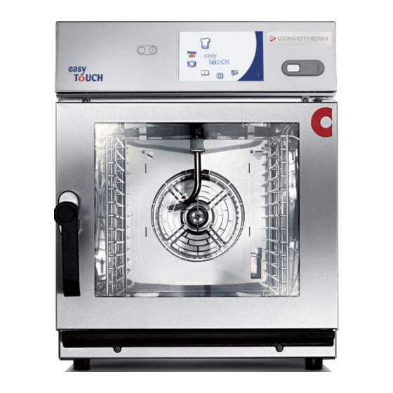
Page 24: Chapter 4 Identification And Major Component Function
Chapter 4 Identification and Major Component Function OES 6.10 Door gasket – Seals oven door. 8) Rack guide – Used to hold trays or containers during cooking 2) USB Slot – Accepts USB drives. 9) Rating plate – Used to identify 3) Door handle –... -
Page 25: Chapter 5 Equipment Set-Up And Close Procedures
Select a recipe desired Chapter 5 Equipment Set-up and Close Procedures 5.1 Crew Mode - The Combi oven performs the following routine when switched ON. Self-test performed Hood switched on The oven light turns on The Start page is displayed ... - Page 26 Open door and load trays onto specified rack Confirm the cook cancel by pressing the positions checkmark. Close the door to start a cook. The timer will begin to count down. Alarm will sound when cook cycle is completed. Open the door and remove the highlighted rack. Various products can be cooked together.
-
Page 27: Manager Mode
5.2 Manager Mode – In this mode the store Press the Groups button. manager can adjust recipes and change minor system settings. 5.2.1 Add/Remove Recipes to Groups, Edit Recipe Cook Times The Manager can use following sequence to add or remove recipes to various menu groups. -
Page 28: Removing A Recipe
5.2.2 Removing a Recipe 5.2.3 Adding a Recipe 1. Locate the recipe to remove from a group in 1. Locate the recipe to add to a group in the right the left column. column. 2. Highlight the recipe you want to remove (i.e. 2. -
Page 29: Edit Recipe Cook Times
5.2.5 Edit Recipe Cook Times Press the Groups button. The Manager can use following sequence to calibrate / check a recipe. While in crew mode, select the back button to exit crew mode. Press the Recipe Group button with the product to edit. - Page 30 Use the keypad to enter the new time including Press the back button two (2) times to exit back to seconds to make changes. Adjust in 30 second the main menu. increments until desired results are achieved. Press the OK button to accept the time change. Press Crew Mode to return to cooking screen.
-
Page 31: Changing Limited Settings
5.2.6 Changing Limited Settings The Manager can use following sequence to calibrate / check a recipe. Select “service agent mode” on start screen. Enter Manager Password (default “1qaz”) and press the checkmark. Access on limited settings will appear. Select the icon of the setting or function to modify. -
Page 32: Automatic Cleaning
When cleaning is finished a sequence of screens Automatic Cleaning will appear Activated cleaning modes are preset at 2- End of cleaning cycle minute Quick Rinse, Daily Cleaning, Weekly Oven will shut off light and heaters Cleaning and Deep Cleaning. ... -
Page 33: Chapter 6: Troubleshooting, Power Failure And Service And Parts/Service
Chapter 6 Troubleshooting, Power Failure and Parts/Service Code Failure Display Actions Troubleshooting Guide No start possible. Call for Error of Checksum of IDM Service Code Failure Display Actions identification is wrong or module damaged. E01.0 No or low water Verify No Water pressure supply is... -
Page 34: In The Event Of A Power Failure
In the Event of a Power Failure Do NOT attempt to operate a MINI during a power failure! DEATH, INJURY, and EQUIPMENT DAMAGE can result. Follow the Power Failure Shutdown Instructions. POWER FAILURE SHUTDOWN INSTRUCTIONS In the event of a power failure: 1. -
Page 35: Chapter 7 Planned Maintenance
Chapter 7 Planned Maintenance Page 1 of 1 29_00 10/2011 ©McDonald’s Corporation · Planned Maintenance Manual · Revised December 2015... - Page 36 Cleaning of door gasket Daily PR 28 D1 To prevent steam leaks and to increase durability of gasket 2 minutes to prepare 3 minutes to complete Time required Time of day End of day For 24-hour restaurants: 4am Hazards Chemicals can cause irritation of eyes. Always follow directions for use on packages and refer to Material Safety Data Sheet (MSDS) as required.
- Page 37 Cleaning of appliance surface Daily PR 28 D2 To keep unit clean 2 minutes to prepare 3 minutes to complete Time required End of day For 24-hour restaurants: 4am Time of day Hazards Chemicals can cause eye and skin irritations at higher concentrations. Avoid contact with your eyes and skin and always follow directions for use on packages and refer to Material Safety Data Sheet (MSDS) as required.
- Page 38 Cleaning of double glass door Weekly PR 28 W1 To keep glass door clean 2 minutes to prepare 4 minutes to complete Time required End of day For 24-hour restaurants: 4am Time of day Hazards Chemicals can cause eye and skin irritations at higher concentrations. Avoid contact with your eyes and skin and always follow directions for use on packages and refer to Material Safety Data Sheet (MSDS) as required.
- Page 39 Cleaning of double glass door (continued) Re-close double glass door Re-close the double glass door using the quick-release catches (1). Page 2 of 2 7018003_00 10/2011 ©McDonald’s Corporation · Planned Maintenance Manual · Revised December 2008...
- Page 40 Cleaning of (0ptional) Hood Front Screen Weekly PR 28 W2 To keep front hood screen clean 3 minutes to prepare 3 minutes to complete Time required End of day For 24-hour restaurants: 4am Time of day Hazards Chemicals can cause eye and skin irritations at higher concentrations. Avoid contact with your eyes and skin and always follow directions for use on packages and refer to Material Safety Data Sheet (MSDS) as required.
- Page 41 Check ventilation slits Quarterly PR 28 Q1 To prevent blockages in air flow Time required 2 minutes to prepare 1 minute to complete End of day For 24-hour restaurants: 4am Time of day Hazards Hot surfaces can cause burns. Wait until the oven has cooled down and wear personal protective equipment (PPE).
- Page 42 Replace Charcoal Filter Quarterly PR 28 Q2 To prevent blockages in air flow 5 minutes to prepare 10 minutes to complete Time required End of day For 24-hour restaurants: During low-volume periods. Time of day Hazards Tools and supplies Procedure Turn off hood Insert Filter Be sure the hood is...
- Page 43 Replacement of door gasket Semi-annual PR 28 S1 T To prevent steam leakage 2 minutes to prepare 5 minutes to complete Time required Low-usage period For 24-hour restaurants: Low-usage period Time of day Hazards Hot surfaces can cause burns. Wait until the cooking chamber has cooled down and wear personal protective equipment (PPE).
- Page 44 Replacement of oven light and oven light seal Semi-annual PR 28 S2 T To prevent bulb failure 2 minutes to prepare 5 minutes to complete Time required Low-usage period For 24-hour restaurants: Low-usage period Time of day Hazards Hot surfaces can cause burns. Wait until the oven has cooled down and wear personal protective equipment (PPE).
- Page 45 Retrieve information from Logbook Annual PR 28 A1 T To save error log and other unit related data 2 minutes to prepare 5 minutes to complete Time required Low-usage periods For 24-hour restaurants: Low-usage periods Time of day Hazards Tools and supplies Pen drive Procedure 3 Resolve failure...
- Page 46 Check warning signs Annual PR 28 A2 T Check if all warning signs are available 2 minutes to prepare 2 minutes to complete Time required Low-usage period For 24-hour restaurants: low-usage period Time of day Hazards Tools and supplies Label: Warning of Label: Warning of Label: Warning of Label: Warning of...
- Page 47 Check safety devices Annual PR 28 A3 T To maintain highest protection level 1 minute to prepare 5 minutes to complete Time required Low-usage period For 24-hour restaurants: Low-usage period Time of day Hazards Hot liquid/steam can cause burns. Wait until the cooking chamber has cooled down and wear personal protective equipment (PPE).
- Page 48 Check safety devices (continued) Check door gasket Check if hygienic plug-in door gasket is damaged or worn/torn and replace if necessary. Check suction panel Check if catches of suction panel are securing the panel properly. Replace if necessary. Check rack Check rack for bent retainers or cracked welds or if rack is bent.
- Page 49 Check installation, connections and hoses Annual PR 28 A4 T Prevent appliance failures 5 minutes to prepare 25 minutes to complete Time required Low-usage period For 24-hour restaurants: Low-usage period Time of day Hazards Chemicals can cause eye and skin irritations. Avoid contact with your eyes and skin and always follow directions for use on packages and refer to Material Safety Data Sheet (MSDS) as required.
- Page 50 Check installation, connections and hoses (continued) Check seal of top box Check sensor seal Check whether the seal between the top box and the cooking chamber provides a continuous seal. Check the seal for the oven sensor (B6). Replace the seal if it is damaged. Tighten the screw.
- Page 51 Check installation, connections and hoses (continued) Check hoses Check all hoses for wear (1). Items to check include: Water hoses • Cleaning-agent hoses • Replace any hoses that are damaged or leaking. Check chemicals filter Check that the filter unit is fitted at the end of the rinse- agent hose.
- Page 52 Check water quality Annual PR 28 A5 T Preventing appliance failures 3 minutes to prepare 10 minutes to complete Time required Low-usage period For 24-hour restaurants: Low-usage period Time of day Hazards Operating certain actuators will start the fan or the heater, which may cause severe injury to the hands or entangle hair/clothing or cause burns.
- Page 53 Check of water quality (continued) Fill sample container Remove sprinkler nozzle Rinse the sample container with the sampled water. Fill Unscrew and remove the sprinkler nozzle. Position the the sample container. sample container on a tray under the opened water supply.
- Page 54 Check of water quality (continued) Check general hardness Measure the general hardness (GH). Pour 5ml of sampled water into an analysis container for each water type. One drop of the analysis liquid is equivalent to 1°dH. CAUTION! Chemicals can cause eye and skin irritations. Check carbonate hardness Measure the carbonate hardness (KH) Pour 5ml of sampled water into an analysis container...
- Page 55 Check electrical installation and components Annual PR 28 A6 T Preventing an appliance failure 10 minutes to prepare 15 minutes to complete Time required Time of day Low-usage period For 24-hour restaurants: Low-usage period Hazards When the cover is open, there is a risk of electric shock from touching live parts. Make sure that any work on the electrical system is performed by a qualified electrician.
- Page 56 Check electrical installation and components (continued) Check electrical installation Check plug-in connections Check the electrical installation: Check that all plug-in connections (1) are firmly in Equipment provided by customer is installed and place. Plug in the connectors correctly. Items to check installation complies with electrical installation include: •...
- Page 57 Functional testing Annual PR 28 A7 T Prevent an appliance failure 5 minutes to prepare 10 minutes to complete Time required Low-usage period For 24-hour restaurants: Low-usage period Time of day Hazards When the cover is open, there is a risk of electric shock from touching live parts. Make sure that any work on the electrical system is performed by a qualified electrician from an approved customer service office.
- Page 58 Check function Check whether: • The oven light is on for 60 seconds after opening the appliance door • The fan is running • The temperature inside the oven is rising • The heater switches off at 302°F (150°C) • No steam is escaping from the appliance...
-
Page 59: Chapter 8 Wiring Diagrams
Chapter 8 Wiring Diagrams... - Page 62 DELFIELD® FRYMASTER® KOLPAK® MANITOWOC® MERRYCHEF® CONVOTHERM® FITKITCHEN™ GARLAND LINCOLN MERCO® MULTIPLEX® ©2019 Welbilt Inc. except where explicitly stated otherwise. All rights reserved. Continuing product improvement may necessitate change of specifications without notice. Part Number CON_IOM_8197346 08/2019...
Need help?
Do you have a question about the Convotherm OES 6.10 Mini and is the answer not in the manual?
Questions and answers