Welbilt Convotherm 4 Installation Manual
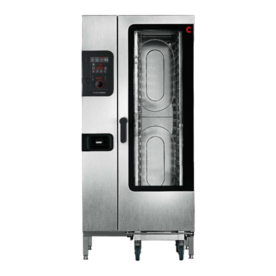
Combi oven
Hide thumbs
Also See for Convotherm 4:
- Training manual (156 pages) ,
- User manual (116 pages) ,
- Operating manual (115 pages)

Subscribe to Our Youtube Channel
Related Manuals for Welbilt Convotherm 4


Summary of Contents for Welbilt Convotherm 4
- Page 1 Combi oven Convotherm 4 C4 floor-standing units Installation manual - Original, ENG Advancing Your Ambitions...
-
Page 3: Table Of Contents
Table of Contents Table of Contents General information Environmental protection Identifying your combi oven Structure of customer documentation About this installation manual Essential reading relating to safety Design and function Design and function of the combi oven Layout and function of the operating panel For your safety Basic safety code Intended use of your combi oven... - Page 4 9.26 Water consumption, cooking and cleaning Connection diagrams 10.1 Convotherm 4 12.20 electric appliance 10.2 Convotherm 4 12.20 boiler gas appliance 10.3 Convotherm 4 12.20 injection gas appliance 10.4 Convotherm 4 20.10 electric appliance 10.5 Convotherm 4 20.10 boiler gas appliance 10.6...
- Page 5 Table of Contents 10.9 Convotherm 4 20.20 injection gas appliance Installation manual...
-
Page 6: General Information
1 General information 1 General information 1.1 Environmental protection Statement of principles Our customers' expectations, the legal regulations and standards and our company's own reputation set the quality and serv- ice for all our products. We have an environmental management policy that not only ensures compliance with all environmental regulations and laws, but also commits us to continuous improvement of our green credentials. -
Page 7: Identifying Your Combi Oven
Layout of the type plate on electric appliances Item Name Name of appliance Combi oven Trade name Element Meaning Convotherm 4 appliance series easyTouch controls easyDial controls numbers xx.yy Appliance size Electric appliance with boiler Electric appliance with water injection for appliances with an NSF certificate... - Page 8 Type plate Additional plate Name Name of appliance Combi oven Trade name Element Meaning Convotherm 4 appliance series easyTouch controls easyDial controls numbers xx.yy Appliance size Gas appliance with boiler Gas appliance with water injection for appliances with an NSF...
-
Page 9: Structure Of Customer Documentation
1 General information 1.3 Structure of customer documentation Contents of the appliance documentation Book type Contents Installation manual Describes how to move, set up and install the appliance, and how to put the appliance ■ into service Describes the hazards and appropriate preventive measures relevant to all installation ■... -
Page 10: Essential Reading Relating To Safety
1 General information 1.5 Essential reading relating to safety Safety information in the customer documentation Safety information relating to the combi oven appears only in the installation manual and the user manual. The installation manual contains the safety information for the tasks covered by the manual and which are performed when moving, setting up and installing the appliance and when putting the appliance into service and removing the appliance from service. -
Page 11: Design And Function
2 Design and function 2 Design and function 2.1 Design and function of the combi oven Components and function (electric appliances) The following illustration shows a size 20.20 combi oven as an example for all electric appliances: Item Name Function Ventilation port External air intake for removing the moisture from the cooking chamber ■... - Page 12 2 Design and function Item Name Function Ventilation slots underneath the Used for appliance ventilation ■ appliance Must not be covered ■ Core temperature probe, sous- Measures the core temperature of the food being cooked ■ vide sensor (optional) Available in two connection options: permanent internal connection or tempo- ■...
- Page 13 2 Design and function Item Name Function Cooking chamber Contains the food during cooking operation Built-in preheat bridge in appli- Used for safety purposes during preheating and reduces energy wastage ance door Loading trolley Holds standard-sized food containers Recoil hand shower Intended solely for rinsing out the cooking chamber with water ■...
-
Page 14: Layout And Function Of The Operating Panel
2 Design and function 2.2 Layout and function of the operating panel Layout and elements of the easyTouch operating panel Item Name Function Appliance Switches the combi oven on and off ON/OFF switch USB port For connecting a USB stick Full touch screen Central controls for appliance display... -
Page 15: For Your Safety
3 For your safety 3 For your safety Purpose of this chapter This chapter provides you with all the information you need in order to use the combi oven safely without putting yourself or others at risk. This is a particularly important chapter that you should read through carefully. Basic safety code Object of this safety code This safety code aims to ensure that all persons who use the combi oven have a thorough knowledge of the hazards and... -
Page 16: Intended Use Of Your Combi Oven
3 For your safety Intended use of your combi oven Intended use The combi oven is designed and built solely for cooking different foodstuffs in standard-sized food containers (e.g. Gas- ■ tronorm containers, standard baking trays). Steam, convection and combi-steam (non-pressurized superheated steam) are used for this purpose. -
Page 17: Warning Signs On The Combi Oven
3 For your safety Warning signs on the combi oven Positioning of warning signs The following illustration shows a size 20.20 electric combi oven as an example of all floor-standing units: Loading trolley Obligatory warning signs The following warning signs must be attached to the combi oven and accessories in the area indicated so as to be easily visible at all times. - Page 18 3 For your safety Range Warning sign Description Tip-over hazard warning for the loading trolley There is a risk of the loading trolley toppling over if moved. Always take great care when moving the loading trolley. When moving the loading trolley, watch out for ob- jects in the way or unevenness in the floor.
-
Page 19: Owner Obligations
3 For your safety Owner obligations Personnel for working at the combi oven The owner must ensure that all work relating to conveying, setting up and installing the appliance, and taking the appliance out of service, is performed solely by qualified personnel as specified in 'Requirements to be met by personnel, working positions' on page 25. -
Page 20: Hazards Arising From The Appliance
3 For your safety Hazards arising from the appliance General rules for working with the appliance The combi oven is designed to protect the user from all hazards that can reasonably be avoided by design measures. The actual purpose of the combi oven, however, means that there are still residual risks; you must therefore take precautions to avoid them. - Page 21 3 For your safety Lack of oxygen In the kitchen, gas appliances can cause the following hazards: Risk of suffocation from lack of breathable air Where? Where appliance is installed ■ How can I avoid the hazard? Check the exhaust gas readings and if the readings are not acceptable, get a certified gas installation engineer from an authorized service company to adjust the burner Ensure that a ventilation system is in place, is working properly and is running, and that the ventilation requirements stipulated by the gas installation engineer are met...
- Page 22 3 For your safety Live parts The following hazards can arise at the appliance when performing any installation work: Risk of electric shock from live parts Where? Under covers ■ Under the operating panel ■ On the mains power lead ■...
-
Page 23: Safety Devices
3 For your safety Safety devices Meaning The combi oven has a number of safety devices to protect the user from hazards. It is absolutely essential that all safety devices are fitted, secured correctly and in working order when operating the combi oven. Position and function The following illustration shows a size 20.20 electric combi oven as an example of all floor-standing units: Item... - Page 24 3 For your safety Item Protective device Function Check Disconnector Installed by the customer close to Action: ■ the appliance; easily visible and Trip the disconnector ■ (installed by accessible, 3-pole action, mini- Check at the -X10 terminal strip on customer) ■...
-
Page 25: Requirements To Be Met By Personnel, Working Positions
3 For your safety Requirements to be met by personnel, working positions Requirements to be met by personnel The table shows the skills required to perform the specified roles. One person may perform more than one role depending on need and organization of work, provided this person has the skills required for the role concerned. Role Skills required Tasks... - Page 26 3 For your safety Working positions when installing the appliance and putting the appliance into service The working position for personnel installing the appliance and putting the appliance into service is the entire appliance area. Installation manual...
-
Page 27: Personal Protective Equipment
3 For your safety Personal protective equipment Moving and setting up the appliance Activity Materials used Personal protective equipment Conveying within the establishment Forklift truck or pallet truck Protective gloves ■ ■ Setting up the appliance in the installation Safety boots ■... -
Page 28: Transportation
4 Transportation 4 Transportation 4.1 Conveying the appliance to the installation location Space required for conveying the appliance Make sure that there is enough width and height along the entire route used for conveying the appliance to ensure it can get through to its installation location. -
Page 29: Scope Of Delivery
4 Transportation 4.3 Scope of delivery Appliance and Accessories The following parts are supplied: 1x combi oven ■ 1x loading trolley ■ 1x empty canister (10 litres) for cleaning agent (optional) ■ 1x suction nozzle with hose for cleaning agent (optional) ■... -
Page 30: Setting Up The Appliance
5 Setting up the appliance 5 Setting up the appliance 5.1 Adjacent systems Dealing with the discharged air During operation, the combi oven generates heat and moisture, which mainly escape upwards into the surrounding air as hot vapour from the air vent(s). It is not permitted to connect air ventilation pipes directly to an air vent of the combi oven. The manufacturer recommends using a fume extractor hood or ceiling-fitted ventilation equipment to extract the discharged air from the room in which the combi oven is operating. -
Page 31: Requirements For The Installation Location
5 Setting up the appliance 5.2 Requirements for the installation location Meaning This section contains information to help you choose a suitable installation location for the appliance. Inspect the intended installation location carefully to ensure it is suitable before bringing the appliance there and starting the installation. Regulations for setting up the appliance National, regional and local standards and regulations relating to workplaces in professional kitchens must be observed. - Page 32 5 Setting up the appliance Actual space requirements Far more room than the specified space requirement is needed in front of the appliances to operate the combi ovens safely, in particular to handle hot food safely. For the distance that is actually needed between the top of the combi oven and the ceiling, please refer to the topic 'Adjacent systems' on page 30.
- Page 33 5 Setting up the appliance Space required for disappearing door - width and depth The following diagram and table show the space required for the appliance for different installation and operating situations. They also show the minimum horizontal distances from adjacent walls and surfaces. The safety clearances on the left, right and rear must always be complied with.
- Page 34 5 Setting up the appliance Height requirement The following illustration shows a size 12.20 combi oven as an example for all appliances: The service engineer who is responsible for setting up the appliance must take into account the nature of the ceiling and any adjacent systems that may be used (air ventilation system, vapour extractor hood etc.) when designing the particular clear- ance needed between the top of the appliance and the ceiling.
-
Page 35: Taking The Appliance Off The Pallet
5 Setting up the appliance 5.3 Taking the appliance off the pallet Rules for lifting the appliance safely Observe the following rules to prevent the appliance toppling over: Always lift the appliance carefully and secure it against tipping over. ■ Be aware of the centre of gravity to keep the appliance balanced. - Page 36 5 Setting up the appliance Risk of crushing from the appliance tipping over Before sliding the appliance off the pallet, make sure that the slides ■ are screwed firmly to the pallet. Take care not to let an appliance foot slip off the side of the slide. ■...
- Page 37 5 Setting up the appliance Taking the appliance off the pallet (marine version) Remove the screws from the flanged feet of the appliance that hold the combi oven on the pallet. Use a forklift truck or pallet truck to pick up the appliance. To protect the wheel-in rail (1) for the loading trolley, insert two ■...
-
Page 38: Setting Up A Floor-Standing Unit On The Floor (Standard Model)
5 Setting up the appliance 5.4 Setting up a floor-standing unit on the floor (standard model) Rules for setting up the appliance safely Observe the following rules to ensure that the appliance is installed in a stable situation: It must be possible to set up the appliance in the installation position so that it cannot tip over or slide about. The support- ■... -
Page 39: Setting Up A Floor-Standing Unit On The Floor (Marine Model)
5 Setting up the appliance 5.5 Setting up a floor-standing unit on the floor (marine model) Rules for setting up the appliance safely Observe the following rules to ensure that the appliance is installed in a stable situation: The appliance must be screwed or welded to the floor using the appropriate parts. ■... -
Page 40: Installation
6 Installation 6 Installation 6.1 Electrical installation 6.1.1 Planning the electrical installation Meaning It is crucial to the safe and reliable operation of the appliance that the electrical system is installed carefully and correctly. All the rules and regulations listed here, and the described procedure, must be strictly followed. Rules for safe electrical installation of the appliance Observe the following rules to prevent hazards caused by faulty electrical connections: The case of the appliance must be grounded and connected to the equipotential bonding system in accordance with the... - Page 41 6 Installation Frequency converter (single phase) Frequency converter (three phase) Rated voltage 3~ 220 V 60 Hz 3~ 480 V 60 Hz 3~ 230 V 50/60 Hz 3~ 200 V 50/60 Hz 1N~ 230V 50/60 Hz 1N~ 220V 60 Hz 1N~ 100V 50/60 Hz 1N~ 120V 60 Hz 2~ 230 V 50/60 Hz...
-
Page 42: Carrying Out The Electrical Installation
6 Installation 6.1.2 Carrying out the electrical installation Requirements Check that the following requirement has been met: The connection point of the appliance is disconnected from the customer power supply and protective measures taken to ■ ensure the power cannot be switched on again. Checking the supply ratings and electrical connections Remove the side panel from the appliance. -
Page 43: Connecting An Energy Optimization System
6 Installation 6.1.3 Connecting an energy optimization system Purpose of an energy optimization system You can connect the combi oven to an energy optimization system (e.g. SICOTRONIC). An energy optimization system smooths out peaks in power consumption that occur during operation of your appliances, and can thereby help to reduce your energy costs. - Page 44 6 Installation Tap out the smaller, pre-perforated knock-out in the floor panel of ■ the combi oven, at the position indicated. Insert the cable gland in the knock-out then feed the connecting ca- ■ ble for the energy optimization system through the cable gland into the wiring compartment of the combi oven.
-
Page 45: Connecting The Signal Tower
6 Installation 6.1.4 Connecting the signal tower Purpose of a signal tower A signal tower that is electronically connected to the combi oven indicates the current operating status of your combi oven visually, using three indicator lamps (green, yellow, red), and acoustically. This indicating device provides a signal that can be seen and heard from far away. - Page 46 6 Installation Connect the signal-tower connecting cable to the combi oven in ac- cordance with the PIN assignment shown below. Assignment Wire colour BU (Blue) Signal: buzzer GY (Grey) Signal: red light BK (Black) Signal: yellow light WH (White) Signal: green light BN (Brown) Refit the side panel on the combi oven.
-
Page 47: Connecting The Water-Treatment Filter Monitor
6 Installation 6.1.5 Connecting the water-treatment filter monitor Purpose of the water-treatment filter monitor You can provide an electrical connection from the combi oven to the remote status indicator of a connected water treatment filter. The combi oven software will then monitor the status of the water treatment filter. A warning message tells you when the filter capacity is down to only 10% so that you know that the water treatment filter will need changing soon. - Page 48 6 Installation Connect the connecting cable for the water-treatment filter monitor to the combi oven in accordance with the PIN assignment shown below. Assignment Signal Refit the side panel on the combi oven. Put the combi oven and water-treatment filter monitor into operation. Installation manual...
-
Page 49: Gas Installation
6 Installation 6.2 Gas installation 6.2.1 Planning the gas installation Rules for safe installation of the gas supply to the appliance Observe the following rules to prevent hazards caused by faulty gas connections: The combi oven is supplied from the factory for operation with a defined gas type (see appliance type plate). In order to ■... - Page 50 6 Installation Exhaust gas temperature The temperature of the undiluted exhaust gas can reach 500 °C. Follow fire safety regulations. Installation manual...
-
Page 51: Positions Of The Fan Burners And Main Gas Valve
6 Installation 6.2.2 Positions of the fan burners and main gas valve Position of the fan burners for appliance size 12.20 The following illustration shows a size 12.20 combi oven gas appliance with boiler: Item Name Exhaust outlet from boiler burner (only on models with boiler not steam injection) Exhaust outlet for convection burner Convection burner... - Page 52 6 Installation Position of the fan burners in appliances sizes 20.10 and 20.20 The following illustration shows a size 20.20 combi oven with boiler as an example of gas appliances of size 20.10 and 20.20: Item Name Exhaust outlet from boiler burner (only on models with boiler not steam injection) Exhaust outlet for bottom convection burner Exhaust outlet for top convection burner...
-
Page 53: Installing The Gas
6 Installation 6.2.3 Installing the gas Requirements Check that the following requirement has been met: A gas shut-off device is installed at the customer's premises. ■ Materials required Leak detector spray/gas detector ■ Installing the gas Compare the type of gas, the gas pressure and the rating for the gas 'Data for gas operation' in 'Technical data' supply connection with the data given on the appliance type plate. -
Page 54: Measuring The Supply Flow Pressure
6 Installation 6.2.4 Measuring the supply flow pressure Requirements A gas shut-off device is installed at the customer's premises. ■ The gas has been installed correctly in accordance with the instructions under 'Installing the gas' on page 53 as far as ■... -
Page 55: Measuring The Exhaust Gas Values
6 Installation 6.2.5 Measuring the exhaust gas values Materials required Exhaust gas analyser ■ Measuring the exhaust gas values Guide the measuring sensor (2) of the exhaust gas meter (1) into the exhaust outlet (3) for the burner to be measured. Measure the exhaust gas values. -
Page 56: Network Connection
6 Installation 6.3 Network connection 6.3.1 Planning the network connection Meaning Safe and reliable operation of the appliance depends on access to the Internet, and therefore it is crucial to that the network connection is installed carefully and correctly. Contact your Service partner with regard to this matter. Customer-installed equipment and rules relating to the network connection The table below shows what equipment must be provided by the customer and what regulations must be observed when connecting the appliance. -
Page 57: Connecting To The Network
6 Installation 6.4 Connecting to the network Installation procedure Follow the steps below to establish an Internet connection: Use a network cable to connect the network socket on the combi oven to the network socket which the customer has pre-installed and given clearance for use. -
Page 58: Water Connection
6 Installation 6.5 Water connection 6.5.1 Water supply Regulations for the water connection Water pipes and connections must comply with local and national regulations. In particular these include: DIN 1988 part 2 and part 4 ■ EN 61770 ■ EN 1717 ■... - Page 59 6 Installation Connection diagram without water treatment Connection diagram Connections on the appliance United Kingdom: Item Name Explanation Water connection for boiler and water For water quality see 'Water quality' on page 97 injection Water connection for cleaning system For water quality see 'Water quality' on page 97 and recoil hand shower Water distributor Customer water pipe...
- Page 60 6 Installation Connection diagram with water treatment Connection diagram Connections on the appliance United Kingdom: Item Name Explanation Water connection for boiler and water in- For water quality see 'Water quality' on page 97 jection Water connection for cleaning system For water quality see 'Water quality' on page 97 and recoil hand shower Customer water pipe...
- Page 61 6 Installation Installing the water supply Flush through the customer's water supply pipe (Z). Fit the sediment filter (X) and, if necessary, a water treatment system (W). Fit a separate shut-off device (Y) for each appliance. If a backflow preventer (V) or double check valve (DCV) are required (see connection diagram), fit the relevant device in the water supply line.
-
Page 62: Test The Water Quality
6 Installation 6.5.2 Test the water quality Materials required You will need the following materials: 1 sample container for taking samples ■ 1 conductivity meter (part no. 3019007) ■ Analysis kit for measuring general hardness and carbonate hardness, including two analysis containers (part no. ■... -
Page 63: Drain Connection
6 Installation 6.5.3 Drain connection Regulations for the drain connection You must comply with local and national regulations on the design of the drain connection and on the composition of the wastewater. These include: DIN 1988 part 2 and part 4 ■... -
Page 64: Installing The Fully Automatic Oven Cleaning System
6 Installation 6.6 Installing the fully automatic oven cleaning system 6.6.1 Layout of the fully automatic oven cleaning system Cleaning agent and rinse aid Use only the cleaning fluids specified here to clean the combi oven. NOTICE Damage caused as a result of improper use of cleaning agents will invalidate any warranty claims. The following table shows the approved cleaning agent and rinse aid: Name Product... - Page 65 6 Installation Installation location for the cleaning-agent and rinse aid canisters Install the canisters as follows: The canisters should be located for easy access beside the appliance on a flat surface. ■ The surface on which the canister sits must not lie above the level at which the appliance feet meet the appliance case. ■...
-
Page 66: Connecting The Fully Automatic Oven Cleaning System
6 Installation 6.6.2 Connecting the fully automatic oven cleaning system Connecting the fully automatic oven cleaning system to canisters Mix the supplied ConvoCare Kconcentrate with soft water in the empty ConvoCare rinse aid canister. Follow the instructions in the user manual on mixing the ConvoCare rinse aid in the canister. - Page 67 6 Installation Plug the red extractor tube (4) for the ConvoClean forte or ConvoClean new cleaning agent onto the connector nipple of the front tube fitting (G) and secure the tube in place with the wire clip (3) (see label for cleaning-agent connection on the left-hand side of the appli- ance).
-
Page 68: Installing The Grease Collecting Canister
6 Installation 6.7 Installing the grease collecting canister 6.7.1 Connecting the grease collecting canister Accessories required The ConvoGrill is supplied with the following original accessories, which you need to use in order to connect the automatic grease removal system. Use solely these original accessories: Connecting tube with screw cap for screw-fitting on canister ■... -
Page 69: Putting Into Service
7 Putting into service 7 Putting into service Safe working when putting the appliance into service For your safety when using the combi oven Before putting the combi oven into service, it is essential that you familiarize yourself with the rules and hazard warnings specified in the chapter 'For your safety' in the User manual, and follow the instructions given there. -
Page 70: Procedure For Putting The Appliance Into Service
7 Putting into service 7.2 Procedure for putting the appliance into service Checks prior to putting the appliance into service Before preparing the combi oven for first-time use, check that the following requirements are met: The appliance and fittings or accessories being used show no signs of damage. ■... - Page 71 Check whether steam is being generated in the cooking chamber (Open the appliance door carefully). Only for Convotherm 4 injection appliances: Use the pressure regulator to adjust the pressure to give the correct reading at the pressure gauge in the steam generation water supply: [kPa] 150 (1.5 bar)
-
Page 72: Measuring Appliance Gaps
7 Putting into service 7.3 Measuring appliance gaps Measuring appliance gaps The measured widths of the appliance gaps must lie within the following tolerance ranges: Name Measurement condition Tolerance range Door gap at the front of the appliance The appliance door is closed. 10 ±... -
Page 73: Removal From Service And Disposal
8 Removal from service and disposal 8 Removal from service and disposal 8.1 Removal from service and disposal Rules for safe and responsible working when removing the appliance from service Avoid any risks to yourself and others by following the rules below: The kitchen floor must always be kept dry to reduce the risk of accidents. -
Page 74: Technical Data
9 Technical data 9 Technical data 9.1 Dimensions and weights C4 EB/ES dimensions 12.20 20.10 20.20 Appliance including packaging Width [mm] 1410 1165 1410 Height [mm] 1615 2150 2150 Depth [mm] 1170 1170 Appliance excluding packaging Width for appliance with right-hinged appliance door [mm] 1135 1135... - Page 75 9 Technical data C4 EB weights 12.20 20.10 20.20 Weight excluding packaging without ConvoClean / ConvoClean+ - Right-hinged door [kg] - Disappearing door [kg] with ConvoClean / ConvoClean+ - Right-hinged door [kg] - Disappearing door [kg] Weight of packaging Weight of packaging [kg] C4 ES weights 12.20...
-
Page 76: Maximum Permissible Loading Weight
9 Technical data 12.20 20.10 20.20 Weight of packaging Weight of packaging [kg] 9.2 Maximum permissible loading weight C4 EB/ES/GB/GS The total weight of items placed on the shelf levels must not exceed the maximum permissible loading weight of the combi oven: 12.20 20.10... -
Page 77: Electrical Supply, Eb/Es
9 Technical data 9.3 Electrical supply, EB/ES C4 EB (three-phase FC) 12.20 20.10 20.20 3~ 400V 50/60Hz Rated power consumption [kW] 33.7 38.9 67.3 Convection power [kW] 33.3 38.1 66.5 Steam power [kW] 31.6 31.6 40.2 Motor power [kW] 0.35 Rated current 48.7 56.2... - Page 78 9 Technical data 3~ 230V 50/60Hz (3/PE) Rated power consumption [kW] 33.4 38.2 66.4 Convection power [kW] 33.0 37.8 66.0 Steam power [kW] 31.3 31.3 39.9 Motor power [kW] 0.35 Rated current 84.0 96.0 166.9 Fuse rating Residual current [mA] Protective earth current [mA] Recommended conductor cross-section for wires laid uncovered in air up to 5 m in...
-
Page 79: Electrical Supply, Gb/Gs
9 Technical data 9.4 Electrical supply, GB/GS C4 GB (single-phase FC) 12.20 20.10 20.20 1N~ 230V 50/60Hz (1/N/PE) Rated power consumption [kW] Convection power [kW] Steam power [kW] Motor power [kW] 0.35 Rated current Fuse rating Residual current [mA] 11.5 Protective earth current [mA] Recommended conductor cross-section for wires laid uncovered in air up... -
Page 80: Electrical Supply, Japan
9 Technical data 9.5 Electrical supply, Japan C4 EB/ES (single-phase FC) 12.20 20.10 20.20 3~ 200V 50/60Hz (3/PE) Rated power consumption [kW] 33.4 38.2 66.4 Convection power [kW] 33.0 37.8 66.0 Steam power (EB only) [kW] 31.3 31.3 39.9 Motor power [kW] 0.35 Rated current... -
Page 81: Electrical Supply, Korea
9 Technical data 9.6 Electrical supply, Korea C4 EB/ES (single-phase FC) 12.20 20.10 20.20 3~ 220 V 60 Hz (3/PE) Rated power consumption [kW] 30.6 35.3 61.1 Convection power [kW] 30.2 34.6 60.4 Steam power (EB only) [kW] 28.6 28.6 36.5 Motor power [kW]... -
Page 82: Electrical Supply, Mexico/Nicaragua
9 Technical data 9.7 Electrical supply, Mexico/Nicaragua C4 GB (single-phase FC) 12.20 20.10 20.20 1N~ 120V 60Hz Rated power consumption [kW] Convection power [kW] Steam power [kW] Motor power [kW] Rated current Fuse rating Residual current [mA] Protective earth current [mA] Recommended conductor cross-section for wires laid uncovered in air up 3G2.5... - Page 83 9 Technical data 12.20 20.10 20.20 Rated current Fuse rating Residual current [mA] 11.5 15.0 Protective earth current [mA] Recommended conductor cross-section for wires laid uncovered in air up 3G2.5 3G2.5 3G2.5 to 5 m in length. Residual-current device Type Installation manual...
-
Page 84: Electrical Supply, Marine
9 Technical data 9.8 Electrical supply, marine C4 EB (three-phase FC) 12.20 20.10 20.20 3~ 440V 50/60Hz Rated power consumption [kW] 28.2 32.6 56.3 Convection power [kW] 27.8 31.8 55.5 Steam power [kW] 26.3 26.3 33.6 Motor power [kW] 0.35 Rated current 37.0 42.8... - Page 85 9 Technical data 12.20 20.10 20.20 Rated current 40.3 46.5 80.5 Fuse rating Residual current [mA] Protective earth current [mA] Recommended conductor cross-section for wires laid uncovered in air up to 5 m in 4G16 4G16 4G35 length. Residual-current device Type Installation manual...
-
Page 86: Gas Specification, Natural Gas 2H (E), Natural Gas 2L (Ll), Propane 3P, Liquefied Gas 3B/P
9 Technical data 9.9 Gas specification, natural gas 2H (E), natural gas 2L (LL), propane 3P, liquefied gas 3B/P C4 GB/GS Gas type Natural gas 2H Natural gas 2L Propane 3P Liquefied gas (LL) 3B/P Standard test gas, code G30/G31 Operating materials Natural gas, liquid gas Gas supply values... -
Page 87: Gas Specification, The Netherlands
9 Technical data 9.10 Gas specification, The Netherlands C4 GB/GS Gas type Natural gas 2H Natural gas Propane 3P Liquefied gas 2K** 3B/P Standard test gas, code G25.3 G30/G31 Operating materials Natural gas, liquid gas Gas supply values Gas pipe connection R 3/4"... -
Page 88: Gas Specification, Australia/New Zealand
9 Technical data 9.11 Gas specification, Australia/New Zealand C4 GB/GS Gas type Natural gas Propane (AUS/ Propane 3P Liquefied gas (AUS/NZL) NZL) 3B/P Standard test gas, code G30/G31 Operating materials Natural gas, liquid gas Gas supply values Gas pipe connection R 3/4"... -
Page 89: Gas Specification, Japan
9 Technical data 9.12 Gas specification, Japan C4 GB/GS Gas type Natural gas 13A Propane (JPN) (JPN) Operating materials Natural gas, Propane Gas supply values Gas pipe connection R 3/4" R 3/4" Supply flow pressure [kPa] 2.0 (1.0 - 2.5) 2.8 (2.0 - 3.3) Gas data (as per CE) at 15 °C and 1013 mbar dry Wobbe index (Ws) -
Page 90: Gas Consumption
9 Technical data 9.14 Gas consumption C4 GB/GS 12.20 20.10 20.20 Australia, New Zealand Natural gas (AUS/NZL) Propane (AUS/NZL) G30/G31: Propane 3P / liquefied gas 3B/P [kg/h] Japan Natural gas 13A (JPN) Propane (JPN) [kg/h] Korea LNG: Natural gas 13A (KOR) [m3/h] LPG: Propane (KOR) [kg/h]... -
Page 91: Heat Output, Natural Gas 2H [E], Natural Gas 2L (Ll), Propane 3P, Liquefied Gas 3B/P
9 Technical data 9.16 Heat output, natural gas 2H [E], natural gas 2L (LL), propane 3P, liquefied gas 3B/P C4 GB 12.20 20.10 20.20 G20: Natural gas 2H (E) (referred to lower calorific value H Convection burner [kW] Boiler burner [kW] G25: Natural gas 2L (LL) (referred to lower calorific value H Convection burner... -
Page 92: Heat Output, The Netherlands
9 Technical data 9.17 Heat output, The Netherlands C4 GB 12.20 20.10 20.20 G20: Natural gas 2H (E) (referred to lower calorific value H Convection burner [kW] Boiler burner [kW] G25.3: Natural gas 2K (referred to lower calorific value H Convection burner [kW] Boiler burner... -
Page 93: Heat Output, Australia/New Zealand
9 Technical data 9.18 Heat output, Australia/New Zealand C4 GB 12.20 20.10 20.20 Natural gas (AUS/NZL) Convection burner [MJ/h] Boiler burner [MJ/h] Propane (AUS/NZL) Convection burner [MJ/h] Boiler burner [MJ/h] G30/G31: Propane 3P* (referred to lower calorific value H Convection burner [kW] Boiler burner [kW]... -
Page 94: Heat Output, Korea
9 Technical data 9.20 Heat output, Korea C4 GB 12.10 20.10 20.20 LNG: Natural gas 13A (KOR) Convection burner [kW] Boiler burner [kW] LPG: Propane (KOR) Convection burner [kW] Boiler burner [kW] C4 GS 12.10 20.10 20.20 Natural gas 13A (KOR) Convection burner [kW] Propane (KOR) -
Page 95: Dissipated Heat
9 Technical data 9.21 Dissipated heat C4 EB/ES 10.10 20.10 20.20 With appliance door closed Latent heat [kJ/h] 6900 6900 11000 [kW] 1.92 1.92 3.06 Sensible heat [kJ/h] 7800 8900 14100 [kW] 2.17 2.47 3.92 C4 GB/GS 12.20 20.10 20.20 With appliance door closed Latent heat [kJ/h]... - Page 96 9 Technical data Waste water temperature [°C] max. 80 Slope for drain pipe min. 3.5% (2°) Safety overflow [mm] 80 x 25 mm Installation manual...
-
Page 97: Water Quality
9 Technical data 9.23 Water quality EB/GB Water hardness for both water-supply connections: Cleaning, recoil hand shower (A) and boiler (B) Water quality Drinking water ■ Hard water ■ German degrees of hardness (general hardness: GH) [°dH] 4 - 20 French degrees of hardness [°fH] 7 - 35... -
Page 98: Boiler
9 Technical data ES/GS Water hardness for water connection (A) for water injection Water quality Drinking water ■ Soft water ■ German degrees of hardness (general hardness: GH) [°dH] 4 - 7 French degrees of hardness [°fH] 7 - 13 English degrees of hardness [°e] 5 - 9... - Page 99 9 Technical data C4 ES/GS 12.20 20.10 20.20 Hard water and soft water Average consumption without cleaning [l/h] 13.3 12.2 17.7 Maximum possible water flow rate [l/min] Soft water (specification of water treatment system) Average consumption without cleaning [l/h] 11.8 Maximum possible water flow rate [l/min] Installation manual...
-
Page 100: Water Consumption, Cooking And Cleaning
9 Technical data 9.26 Water consumption, cooking and cleaning C4 EB/GB 12.20 20.10 20.20 Hard water and soft water Average water consumption including cleaning [l/h] 14.2 13.7 17.1 C4 ES/GS 12.20 20.10 20.20 Hard water and soft water Average water consumption including cleaning [l/h] 17.0 15.9... -
Page 101: Connection Diagrams
10 Connection diagrams 10 Connection diagrams 10.1 Convotherm 4 12.20 electric appliance Dimensions and connection points for C4 12.20 (right-hinged appliance door) Front view Connection points in appliance floor Detailed view of drain connection * Distance depends on how far the appliance feet are extended (max. - Page 102 10 Connection diagrams Dimensions and connection points for C4 12.20 (disappearing door) Front view Connection points in appliance floor Detailed view of drain connection * Distance depends on how far the appliance feet are extended (max. +25 mm) View from above with wall clearances Meaning of labelled elements Water connection Soft water G 3/4'' Water connection Hard water G 3/4''...
-
Page 103: Convotherm 4 12.20 Boiler Gas Appliance
10 Connection diagrams 10.2 Convotherm 4 12.20 boiler gas appliance Dimensions and connection points for C4 12.20 (right-hinged appliance door) Front view Connection points in appliance floor Detailed view of drain connection * Distance depends on how far the appliance feet are extended (max. +25 mm) - Page 104 10 Connection diagrams Dimensions and connection points for C4 12.20 (disappearing door) Front view Connection points in appliance floor Detailed view of drain connection * Distance depends on how far the appliance feet are extended (max. +25 mm) View from above with wall clearances Meaning of labelled elements Water connection Soft water G 3/4'' Water connection Hard water G 3/4''...
-
Page 105: Convotherm 4 12.20 Injection Gas Appliance
10 Connection diagrams 10.3 Convotherm 4 12.20 injection gas appliance Dimensions and connection points for C4 12.20 (right-hinged appliance door) Front view Connection points in appliance floor Detailed view of drain connection * Distance depends on how far the appliance feet are extended (max. +25 mm) - Page 106 10 Connection diagrams Dimensions and connection points for C4 12.20 (disappearing door) Front view Connection points in appliance floor Detailed view of drain connection * Distance depends on how far the appliance feet are extended (max. +25 mm) View from above with wall clearances Meaning of labelled elements Water connection Soft water G 3/4'' Water connection Hard water G 3/4''...
-
Page 107: Convotherm 4 20.10 Electric Appliance
10 Connection diagrams 10.4 Convotherm 4 20.10 electric appliance Dimensions and connection points for C4 20.10 (right-hinged appliance door) Front view Connection points in appliance floor Detailed view of drain connection * Distance depends on how far the appliance feet are extended (max. +25 mm) - Page 108 10 Connection diagrams Dimensions and connection points for C4 20.10 (disappearing door) Front view Connection points in appliance floor Detailed view of drain connection * Distance depends on how far the appliance feet are extended (max. +25 mm) View from above with wall clearances Meaning of labelled elements Water connection Soft water G 3/4'' Water connection Hard water G 3/4''...
-
Page 109: Convotherm 4 20.10 Boiler Gas Appliance
10 Connection diagrams 10.5 Convotherm 4 20.10 boiler gas appliance Dimensions and connection points for C4 20.10 (right-hinged appliance door) Front view Connection points in appliance floor Detailed view of drain connection * Distance depends on how far the appliance feet are extended (max. +25 mm) - Page 110 10 Connection diagrams Dimensions and connection points for C4 20.10 (disappearing door) Front view Connection points in appliance floor Detailed view of drain connection * Distance depends on how far the appliance feet are extended (max. +25 mm) View from above with wall clearances Meaning of labelled elements Water connection Soft water G 3/4'' Water connection Hard water G 3/4''...
-
Page 111: Convotherm 4 20.10 Injection Gas Appliance
10 Connection diagrams 10.6 Convotherm 4 20.10 injection gas appliance Dimensions and connection points for C4 20.10 (right-hinged appliance door) Front view Connection points in appliance floor Detailed view of drain connection * Distance depends on how far the appliance feet are extended (max. +25 mm) - Page 112 10 Connection diagrams Dimensions and connection points for C4 20.10 (disappearing door) Front view Connection points in appliance floor Detailed view of drain connection * Distance depends on how far the appliance feet are extended (max. +25 mm) View from above with wall clearances Meaning of labelled elements Water connection Soft water G 3/4'' Water connection Hard water G 3/4''...
-
Page 113: Convotherm 4 20.20 Electric Appliance
10 Connection diagrams 10.7 Convotherm 4 20.20 electric appliance Dimensions and connection points for C4 20.20 (right-hinged appliance door) Front view Connection points in appliance floor Detailed view of drain connection * Distance depends on how far the appliance feet are extended (max. +25 mm) - Page 114 10 Connection diagrams Dimensions and connection points for C4 20.20 (disappearing door) Front view Connection points in appliance floor Detailed view of drain connection * Distance depends on how far the appliance feet are extended (max. +25 mm) View from above with wall clearances Meaning of labelled elements Water connection Soft water G 3/4'' Water connection Hard water G 3/4''...
-
Page 115: Convotherm 4 20.20 Boiler Gas Appliance
10 Connection diagrams 10.8 Convotherm 4 20.20 boiler gas appliance Dimensions and connection points for C4 20.20 (right-hinged appliance door) Front view Connection points in appliance floor Detailed view of drain connection * Distance depends on how far the appliance feet are extended (max. +25 mm) - Page 116 10 Connection diagrams Dimensions and connection points for C4 20.20 (disappearing door) Front view Connection points in appliance floor Detailed view of drain connection * Distance depends on how far the appliance feet are extended (max. +25 mm) View from above with wall clearances Meaning of labelled elements Water connection Soft water G 3/4'' Water connection Hard water G 3/4''...
- Page 117 10 Connection diagrams 10.9 Convotherm 4 20.20 injection gas appliance Dimensions and connection points for C4 20.20 (right-hinged appliance door) Front view Connection points in appliance floor Detailed view of drain connection * Distance depends on how far the appliance feet are extended (max. +25 mm)
- Page 118 10 Connection diagrams Dimensions and connection points for C4 20.20 (disappearing door) Front view Connection points in appliance floor Detailed view of drain connection * Distance depends on how far the appliance feet are extended (max. +25 mm) View from above with wall clearances Meaning of labelled elements Water connection Soft water G 3/4'' Water connection Hard water G 3/4''...
- Page 120 Order no. Additional technical documentation can be found in the download center at : www.convotherm.com Welbilt offers fully-integrated kitchen systems and our products are backed by KitchenCare aftermarket parts and service. Welbilt’s portfolio of award- ® winning brands includes Cleveland™, Convotherm ®...
Need help?
Do you have a question about the Convotherm 4 and is the answer not in the manual?
Questions and answers