Advertisement
SISPM1040-382-LRT Quick Start Guide
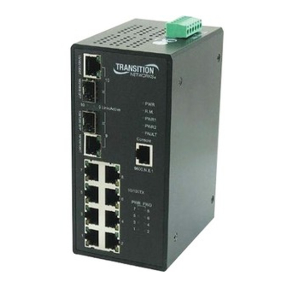
SISPM1040-382-LRT Managed Hardened Fast Ethernet Switch
Quick Start Guide
The SISPM1040-382-LRT is a managed PoE switch for connecting and powering devices in challenging environments. Two gigabit speed combo ports are provided,
allowing copper or fiber SFP uplink ports. The two uplink ports can also be used in a redundant ring for maximum network reliability. The switch has a PoE power
budget of 240 Watts, provides up to 30 Watts per port on all ports simultaneously, has redundant input power connections, and a fault alarm relay to ensure safe
reliable operation in temperatures between -40°C and +75°C without SFPs. See the full User Guide for important information on Product Alerts, Hardware, LEDs,
Cabling, SFPs, Web Management, Login, Command Line Interface (CLI), Technical Specifications, Power Supply specs, Service, Warranty & Compliance, and Regulatory Agency Information.
Hardware Installation
DIN-Rail: Each switch has a DIN-Rail kit that can be mounted on the rear panel. Mount the DIN-Rail Clip. Wall Mount: A wall mount bracket can be used to mount the switch on a panel or
wall. The bracket is mounted to the switch using the enclosed screws.
PoE Ports: Port 1 ~ 8 contain PoE+ function. Compliant with IEEE802.3at PoE+ specifications. Compliant with 802.3at in Environment A when using an isolated
power supply. For 802.3at Environment B applications: 1) use an isolated AC/DC power source, e.g. TN 25080, and/or 2) use mid-span injector (s), e.g. MIL-L100i,
L1000i-at, between this switch's PSE port and link partner PD port.
SFPs: The switch has fiber optical ports with SFP connectors. See the Transition Networks
SFP page
for more information. See the related SFP manual for safety cautions and warnings.
Status LEDs: Power (PWR, PWR1, PWR2), Ring Master (R.M.), Ring, Fault, Port Link/Act, and Port PoE.
Reset button: Push the front panel Reset button for 2 to 3 seconds to reset the switch. Push the Reset button for 5 seconds to reset the switch to its Factory Default settings.
+
+
–
Power Connection: Connect wires between the
terminals on the power supply and the
terminals on the switch terminal block. Do the same with the
terminals.
Maintain correct polarity (not reverse polarity protected). Proper Earth Ground Isolation: For PoE applications, to achieve full isolation between PSE (switch port) and load (PD), the switch
must be powered with a 1500 VAC / 2250 VDC isolated power supply. For applications requiring additional isolation, 1) use an isolated AC/DC power source, e.g. TN 25104, and/or
2) use mid-span injector (s), e.g. MIL-L100i, L1000i-at, between this switch's PSE port and link partner PD port. In addition, earth ground should be connected to the switch chassis.
WARNING: This case must be earth grounded. No DC input may be earth grounded. Use an Isolated Power Supply. See the full User Guide for important details and
Cautions
and Warnings.
Management Software
The SISPM1040-382-LRT can be managed via the Web, TELNET, Console or other third-party SNMP software.
Console Cable: The SISPM1040-382-LRT can be management via console port. A DB-9 to RJ-45 cable is included in the package. Connect the cable to a serial port on the PC via the RS-232
DB-9 female connector and the other end (RJ-45 connector) to the switch console port.
33721 Rev. A
https://www.transition.com
Page 1 of 2
Advertisement
Table of Contents

Related Manuals for Transition Networks SISPM1040-382-LRT


Summary of Contents for Transition Networks SISPM1040-382-LRT
- Page 1 The SISPM1040-382-LRT can be managed via the Web, TELNET, Console or other third-party SNMP software. Console Cable: The SISPM1040-382-LRT can be management via console port. A DB-9 to RJ-45 cable is included in the package. Connect the cable to a serial port on the PC via the RS-232 DB-9 female connector and the other end (RJ-45 connector) to the switch console port.
- Page 2 Trademarks: All trademarks and registered trademarks are the property of their respective owners. Copyright Notice/Restrictions: Copyright © 2013-2017 Transition Networks. All rights reserved.No part of this work may be reproduced or used in any form or by any means (graphic, electronic or mechanical) without written permission from Transition Networks. The information contained herein is confidential property of Transition Networks, Inc.
Need help?
Do you have a question about the SISPM1040-382-LRT and is the answer not in the manual?
Questions and answers