Table of Contents
Advertisement
Available languages
Available languages
Quick Links
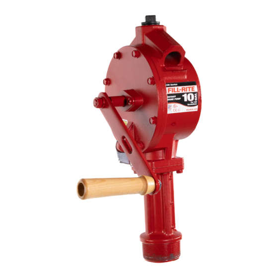
SERIES 100 ROTARY HAND PUMP
AND MODEL 111 COUNTER
ASSEMBLY
Owner's Operation & Safety Manual
Owner's Operation & Safety Manual
Owner's Operation & Safety Manual
Owner's Operation & Safety Manual
Owner's Operation & Safety Manual
Models FR110, FR112, FR113
SAFETY INSTRUCTIONS
To ensure safe and efficient operation, it is essential to read and
follow each of these warnings and precautions.
1. Improper use or installation of this product can cause serious
bodily injury or death.
2. Do NOT smoke near pump or use pump near an open flame when
pumping flammable fluids. Fire could result.
3. A Fill-Rite filter should be used on pump outlet to ensure that no
foreign material is transferred to fuel tank.
4. Use gasoline and oil resistant thread sealant or sealant tape on all
threaded joints to protect against leakage.
5. Storage tank or barrel should be anchored to prevent tipping in
both the full and empty conditions.
6. To minimize static electricity build-up, keep nozzle in contact with
container being filled.
WARNING
This product should not be used for fluid transfer into aircraft. This
product is not suited for use with fluids for human consumption or
fluids containing water.
Fluid Compatibility
If in doubt about compatibility of a specific fluid, contact supplier of fluid
to check for any adverse reactions to the wetted materials.
The 100 is compatible with the following fluids:
•
Gasoline, Diesel, Heptane, Kerosene, Stoddard Solvent, Light Oils,
Mineral Spirits
Do NOT use the 100 with the following fluids:
•
Water, Sulfuric Acid, Naptha, Methanol, Methyl Ethyl Ketone (MEK),
Acetone, Ammonia, Benzene, Bleach, Chlorine
SAFETY APPROVAL
INSTALLATION
NOTE: All pipe threads must have a sealant to protect against leaks.
Use sealant tape provided with the pump, or use a gasoline and oil
resistant pipe sealant.
1. Screw suction pipe into pump inlet flange and tighten.
2. Extend suction pipe into tank or barrel opening to within 3" of
bottom of tank or barrel. Do not rest suction pipe on bottom.
3. Screw inlet flange of pump completely and securely into
undamaged tank or barrel bung.
PUMPS WITH HOSE AND NOZZLE
4. Screw one end of hose into pump discharge opening and the
nozzle to other end of hose.
PUMPS WITH DISCHARGE SPOUTS
4. Screw discharge spout assembly into top of pump.
PUMPS WITH METER, HOSE AND NOZZLE
4. Screw street elbow into top of pump, nipple into street elbow,
meter onto nipple. Note: Position the meter to the right of the
handle facing operator for ease of operator viewing. Screw one
end of hose into meter outlet and the nozzle to the other end of
hose.
COUNTER INSTALLATION
1. Remove crank from shaft.
2. Remove two screws directly above horizontal centerline of
pump.
3. Push drive gear onto shaft with flat in gear hole located on
longer flat of shaft.
4. Position counter on pump and attach with two screws and two
washers.
5. Reattach crank.
PUMP FLOW REVERSAL INSTRUCTIONS
1. Remove the Vacuum Breaker (item 2) and install a pipe plug.
2. Take out Check Valve Assembly (item 25).
3. Turn the handle backwards for reverse flow, normal direction
for normal flow.
TROUBLESHOOTING
IF PUMP FAILS TO PRIME: Check suction line for leaks or obstructions.
Check vanes and slots for nicks, burrs or wear. Check rotor for
excessive wear or damage.
LOW PUMPING CAPACITY: Remove and clean screen. Check for leaks
in suction line. Check rotor and vanes for excessive wear and damage.
Check for dirty filter on outlet side.
PUMP FLUID LEAKAGE: Clean O-ring seal and seat area. Replace seal.
Replace vacuum breaker. Tighten covers and joints. Check for dirty filter
on outlet side.
COUNTER PUMP PARTS LIST
ITM.
ITM.
ITM.
ITM.
ITM.
PART
PART
PART
PART
PART
NO
NO
NO
NO.
NO.
NO.
D E S C R I P T I O N
D E S C R I P T I O N
D E S C R I P T I O N
NO
NO
NO.
NO.
D E S C R I P T I O N
D E S C R I P T I O N
1
100F0890
Counter Back
2
100F0900
Dial Wheel
3
100F1040
#10L Washer
4
100F1050
3/16 Prong-Lock Retainer
5
100F1060
Screw PHMS #8 x 3/8 (Type B)
6
100F0880
Counter Cover
7
100F0910
Dial - 20 Gallon
100F0915
Dial - Liter
8
100F1010
Reset Stop Pin
9
100F1020
Reset Stop Spring
10
704F3811
1/4 Washer
11
100F0921
Reset Knob
12
100F0960
Totalizer Assembly - U.S. Gallon
100F0961
Totalizer Assembly - Liter
13
100F0950
Cluster Gear Shaft
14
800F3830
#2S Washer
15
100F0940
Cluster Gear (12T/33T) - U.S. Gallon
16
100F0970
Drive Gear - Totalizer
17
100F0990
Worm (5T) - U.S. Gallon
100F1001
Worm (2T) - Liter
18
100F0980
Totalizer Shaft
19
100F0930
Drive Gear (41T)
100F0935
Drive Gear (40T) - Liter
20
100F1070
1/4-20 x 1 HHMS
21
100F0945
Cluster Gear (12T/34T) - Liter
22
1200F6565 Washer, Brass
QTY.
QTY.
QTY.
QTY.
QTY.
1
1
1
1
6
1
1
Opt.
1
1
2
1
1
Opt.
2
9
4
1
1
Opt.
1
1
Opt.
2
Opt.
1
Advertisement
Table of Contents

Related Manuals for FILL-RITE 100 Series


Summary of Contents for FILL-RITE 100 Series
- Page 1 Fire could result. Check for dirty filter on outlet side. 3. A Fill-Rite filter should be used on pump outlet to ensure that no PUMP FLUID LEAKAGE: Clean O-ring seal and seat area. Replace seal. foreign material is transferred to fuel tank.
- Page 2 100 SERIES PUMP PARTS LIST ITM. PART ITM. PART DESCRIPTION QTY. DESCRIPTION QTY. H058G9054 8' Hose - UL Listed 100F0720 Vane Spring 5200F1869 Vacuum Breaker 100F0710 Vane 100F0640 Pump Body 30F4540 Crank 100F0660 Cover 100F1085 Wood Grip 100F0801 O-Ring (-159)
- Page 3 1. Remueva la manivela del eje. 2. Remueva los dos tornillos ubicados directamente arriba de la línea central horizontal de la bomba. 3. Empuje el engranaje de impulso en el eje con la parte plana en el agujero del engranaje ubicada en la parte plana más larga del eje. BOMBA DE SERIES 100 4.
- Page 4 LISTA DE PIEZAS BOMBA DE SERIE 100 ART. PIEZA ART. PIEZA DESCRIPCIÓN QTY. DESCRIPCIÓN QTY. 100F0720 Resorte de paleta H058G9054 Manguera Listada UL 100F0710 Paleta 5200F1869 Interruptor de vacío 30F4540 Manivela 100F0640 Cuerpo de la bomba 100F1085 Manija de madera 100F0660 Tapa 100F1086...
- Page 5 INSTALLATION DU DÉBITMÉTRE 1. Déposez la manivelle de l’arbre. 2. Déposez deux vis directement audessus de l’axe horizontal de la pompe. 3. Poussez le pignon moteur sur l’arbre avec le méplat du trou POMPE DE LA SÉRIE 100 d’engrenage positionné sur le méplat plus long de l’arbre. 4.
- Page 6 SERIES 100 - LISTE DES PIÉCES DÉTACHÉES RÉFÉRENCE RÉFÉRENCE ART. DE PIÈCE DESCRIPTION QTÉ ART. DE PIÈCE DESCRIPTION QTÉ H058G9054 100F0720 Ressort de pale Flexible de 2,4 m (8 pi) – Homologué UL 100F0710 Pale 5200F1869 Reniflard 30F4540 Manivelle 100F0640 Corps de la pompe 100F1085 Poignée en bois...
- Page 7 INSTALLATION DES ZÄHLWERKS 1. Kurbel von der Welle. 2. Die beiden, direkt über der horizontalen Pumpenmittellinie befindlichen Schrauben entfernen. 3. Antriebswerk so auf die Welle drücken, dass die ebene Fläche in SERIES 100 KREISELPUMPE der Antriebsöffnung auf der längeren ebenen Fläche der Welle aufliegt.
- Page 8 SERIE 100 PUMPE ERSATXLELLISTE PART IFD. PART BESCREIBUNG QTY. BESCREIBUNG QTY. Schieberfeder 100F0720 H058G9054 Schlauch, 2,5m, UL-eingetr. Schieber 100F0710 5200F1869 Anti-Vakuum-Rückschlagventil Kurbel 100F0640 Pumpengehäuse 30F4540 Holzgriff 100F0660 Abdeckung 100F1085 Griff (einschl. 21, 31, 34) 100F0801 O-Ring (-159) 100F1086 VP1400F8822 #10-24 x 1/2 TORX PH 100F0701 Welle 1/4-20 x 3/4 HWHTRS...
Need help?
Do you have a question about the 100 Series and is the answer not in the manual?
Questions and answers