Table of Contents
Advertisement
Available languages
Available languages
Quick Links
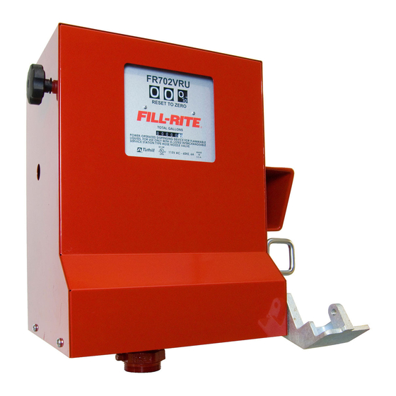
SERIES FR702VR
115 and 230 VOLT AC
FUEL TRANSFER PUMP
Owner's Operation & Safety Manual
Models FR702VR & FR702VER
OUTSTANDING FEATURES
•Up to 18 GPM/68 LPM
•UL listed dispenser & motor
•Full 1/3 HP explosion proof motor
•Meter accuracy of ± 1%
GENERAL DESCRIPTION
The FR702VR compact cabinet pump is based on Fill-Rite's
FR700V positive displacement, direct drive pump, and Fill-Rite's
series 800C nutating disc flow meter which features a flow rate
of 5 to 20 GPM or 19 to 76 LPM and is accurate to within ±1%.
Depending on product viscosity and nozzle selection, the
FR702VR can deliver up to 18 gallons/68 liters of fluid per
minute. This pumping system is UL listed for use with gasoline
and diesel fuel.
The U.S. gallon meter has three resettable wheels, two unit
wheels and a tenth wheel. It's non-resettable totalizer has five
unit wheels and a tenth wheel. The optional liter meter has
three unit wheels which can be reset to zero. It's non-resettable
totalizer has six unit wheels.
OPTIONS
• Automatic nozzles
• Metering in U. S. gallons or liters
• Red or white cabinet paint
• Pedestal for island installations
• 220 VAC, 50/60 Hz
TECHNICAL INFORMATION
esign Features:
D
• 1.25" NPT inlet, 3/4" NPT outlet
• 22 PSI maximum outlet pressure
• Minimum dry vacuum of 10" Hg
• Furnished with 3/4" dia. x 12' hose and manual
nozzle
• Cabinet measures 13"W x 10.94"D x 17.81"H (33 x 27.8 x
43.6 cm)
• Built-in check valve, bypass valve and thermal
expansion valve
• No additional foot valve or check valve needed to
hold prime
• 1/3 HP 115VAC-60Hz, 5.5 amp, 1725 RPM, direct
drive motor
• Ball bearing construction: no lubrication required
• Thermal overload protection
• Explosion proof
• Meter's mechanical totalizer to 100,000 units
• Meter accuracy is ± 1%
• Unit wheels have large 11/16" (18 mm) figures
• Convenient, large reset knob with positive zero stop
• Not for resale use
• Pre-installed Anti-Siphon Valve
FLUID COMPATIBILITY
If in doubt about compatibility of a specific fluid, contact supplier
of fluid to check for any adverse reactions to the wetted materi-
als in the parts list.
SAFETY INSTRUCTIONS
To ensure safe and efficient operation, it is essential to read
and follow each of these warnings and precautions.
1. Improper use or installation of this product can cause
serious bodily injury or death.
2. Do NOT smoke near pump or use pump near an open flame
when pumping flammable fluids. Fire could result.
3. A Fill-Rite filter should be used on pump outlet to ensure
that no foreign material is transferred to fuel tank.
4. Use gasoline and oil resistant thread sealant or sealant tape
on all threaded joints to protect against leakage.
5. Storage tank should be anchored to prevent tipping in both
the full and empty conditions.
6. To minimize static electricity buildup, only use static wire,
conductive hose when pumping flammable fluids and keep
nozzle in contact with container being filled while filling
container.
7. The pump motor is equipped with thermal overload
protection. If overheated, it will shut off without any damage
to the windings. Be sure to turn off the pump power if this
occurs. When the motor cools, it will restart without warning
if power is on.
8. Take motors needing service to an authorized repair shop to
maintain "explosion proof" and "rain proof" integrity.
9. Do not operate without the check valve (700F2661) in place.
Fluid leakage could result.
DANGER
Electrical wiring should be done by a licensed electrician in com-
pliance with local, state and national electric codes.
NEC/ANSI/NFPA 70, NFPA 30, NFPA 30A, as appropriate to the
intended use of the pump. Threaded rigid conduit, seal fittings
and conductor seal should be used. Pump should be properly
grounded. Improper use or installation of this product can cause
serious bodily injury or death.
WARNING
Do not use this product for fluid transfer into aircraft. This prod-
uct is not suited for use with fluids for human consumption or
fluids containing water.
INSTALLATION
GENERAL
Pumps are furnished with a tank adapter for skid tank mounting;
pedestals are available for island installations. All tanks must be
properly vented. A pressure retaining vent/fill cap can be used to
reduce fuel loss due to evaporation but will reduce flow rate.
Fill-Rite filters are recommended when pumping fuels.
Pump has a built-in check valve with pressure relief to prevent
fluid thermal expansion from causing unsafe system pressures.
Do not use additional check valves or foot valves unless
they have a proper pressure relief valve built into them.
Additional check valves will reduce flow rate.
Use a gasoline and oil resistant pipe sealant on all pipe threads
to protect against leaks.
SKID TANK MOUNTING
1. Cut a 1 1/4" pipe that will extend to at least 3"
(8 cm) above bottom of tank when screwed into tank
adapter and tank adapter is screwed into tank flange.
2. Screw pipe into tank adapter, then screw tank adapter into
tank flange.
3. Mount pump on tank adapter.
1
Advertisement
Table of Contents

Related Manuals for FILL-RITE FR702VR Series


Summary of Contents for FILL-RITE FR702VR Series
- Page 1 Fire could result. Models FR702VR & FR702VER 3. A Fill-Rite filter should be used on pump outlet to ensure that no foreign material is transferred to fuel tank. 4. Use gasoline and oil resistant thread sealant or sealant tape OUTSTANDING FEATURES on all threaded joints to protect against leakage.
-
Page 2: Maintenance
DIRECT MOUNTING TO UNDERGROUND ASSEMBLY/DISASSEMBLY Remove power to pump before removing cover. Drain liquid TANK from system before loosening any fittings to prevent excessive 1. Cut and thread both ends of a 2" pipe that will extend about spillage. 31" (79 cm) above the ground when installed in tank Pump Cabinet (see FR702VR cabinet drawing) flange. - Page 3 18.50" 47 cm 13.00" 33 cm CABINET 1.25” 3 cm 17.16" 43.6 cm .75" PUMP 2 cm TANK ADAPTER 600F2129 PEDESTAL PIPE 1.25" SUCTION PIPE 6.56" 10' MAX.-GASOLINE 17 cm (3 m) 1.25" SUCTION PIPE TANK 10' MAX.-DIESEL (3 m) ELECTRICAL CONDUIT 700F3061 PUMP BASE CONCRETE ISLAND...
-
Page 4: Date Of Manufacture
STD. NOZZLE COVER OPTION UNIVERSAL NOZZLE COVER OPTION 66 66A 78 78A DATE OF MANUFACTURE... - Page 5 FR702VR PUMP PARTS LIST ITM. PART ITM. PART DESCRIPTION QTY. DESCRIPTION QTY. 702F1023 BRACKET 704F3640 SCREW 5/16-18 X 1-1/4” HHCS 702F1024 SWITCH HANDLE 704F3680 HEX NUT 5/16-18 (STD. NOZZLE COVER) 702F1027 ROD SWITCH 704F3690 WASHER 5/16” LOCK (STD. NOZZLE COVER) 702F1031 LEVER SWITCH STEEL 704F3811...
-
Page 6: Troubleshooting
TROUBLESHOOTING POSSIBLE CAUSE PROBLEM SOLUTION 1. Suction line problem Check for leaks in suction line 2. Bypass valve open Remove and inspect valve; must move freely & be free of debris 3. Vanes sticking Check vanes and slots for nicks, burrs and wear Pump won't prime 4. - Page 7 The pumps are shipped with a threaded vacuum breaker pump turned off. Fill-Rite has provided a 1/4” NPT opening (#13 on the Pump Parts List) installed. The vacuum break- in the vacuum breaker and tank adapter to plumb the vac- er is used to break a siphon should an open nozzle or a uum breaker back to the tank.
-
Page 9: Instalación
Podría ocurrir un incendio. COMBUSTIBLE SERIE 3. Se deberá usar un filtro Fill-Rite en la salida de la bomba para asegurar de que no se transfieran materiales extraños al FR702VR PARA 115 y 230 Vca tanque de combustible. -
Page 10: Mantenimiento
MONTAJE DIRECTO A UN DEPÓSITO Desarmado 1. Extraiga los cuatro tornillos (elemento 28) para desmontar la SUBTERRÁNEO placa delantera (elemento 8/8A). 1. Corte y rosque ambos extremos de un tubo de 2" de manera que 2. Extraiga los dos tornillos (elemento 43) para desmontar el frente quede a unas 31"... - Page 11 PATINE la INSTALACIÓN del TANQUE INSTALACIÓN 18.50" 47 cm 13.00" 33 cm GABINETE 1.25” " 3 cm 17.16” 43.6 cm .75" 2 cm ADAPTADOR PARA TANQUE 600F2129 6.56" 10' MAX.-GASOLINA 17 cm (3 m) 1.25" TANQUE 10' MAX.-DIESEL (3 m) 700F3061 MÍNIMO 3 PULGADAS (8 cm) INSTALACIÓN DE MONTAJE DIRECTA...
- Page 12 CUBIERTA OPCIONAL PARA BOQUILLA ESTÃNDAR CUBIERTA OPCIONAL PARA BOQUIL- LA UNIVERSAL 66 66A 78 78A FECHA DE FABRICACIÃN...
- Page 13 LISTA DE PIEZAS DE LA BOMBA FR702VR ART. PIEZA ITM. PART DESCRIPCIÓN QTY. DESCRIPTION QTY. 702F1023 SOPORTE 704F3640 TORNILLO 5/16-18 X 1-1/4” HHCS 704F3680 TUERCA HEXAGONAL 5/16-18 (PARA CUBIERTA DE BOQUILLA ESTÁNDAR) 702F1024 MANIJA DEL INTERRUPTOR 702F1027 VARILLA DEL INTERRUPTOR 704F3690 ARANDELA 5/16”...
-
Page 14: Localización De Fallas
LOCALIZACIÓN DE FALLAS PROBLEMA SOLUCIÓN CAUSA POSIBLE 1. Problema en la línea de aspiración Revise la línea de aspiración para verificar si hay fugas 2. Válvula de derivación abierta Extraiga e inspeccione la válvula; debe moverse libremente y estar libre de desperdicios 3. - Page 15 Fill-Rite ha provisto INSTALACIÓN DEL ENTUBADO DEL IGUALADOR DE PRESIÓN La ilustración que sigue muestra un método de instalación para tanque hasta el igualador de presión mediante el uso...
- Page 17 SÉRIE FR702VR Un départ d'incendie serait possible. 3. Un filtre Fill-Rite doit être utilisé en sortie de pompe pour assurer qu'aucune matière étrangère ne sera transférée dans le Guide d'utilisation et de sécurité...
-
Page 18: Entretien
MONTAGE DIRECT SUR RÉSERVOIR Démontage ENTERRÉ 1. Ôter la plaque frontale (référence 8/8A) en enlevant 4 vis 1. Couper et fileter les deux extrémités d'un tuyau de 2" qui sor- (référence 28). tira à environ 31" (79 cm) au dessus du sol une fois installé 2. - Page 19 18.50" 47 cm 13.00" 33 cm COFFRET 1.25” 3 cm 17.16” 43.6 cm .75" LA POMPE 2 cm ADAPTATEUR 600F2129 TUYAU DE PIÉDESTAL 1.25" TUYAU D´ ASPIRATION 6.56" 10' MAX.-ESSENCE 17 cm (3 m) 1.25" TUBE D´ASPIRATION RÉSERVOIR 10' MAX.-DIESEL (3 m) CONDUIT ELECTRIQUE 700F3061 BASE DE LA POMPE...
-
Page 20: Date De Fabrication
OPTION STANDARD DE COUVERTURE DE PISTOLET OPTION UNIVERSELLE DE COUVERTURE DE PISTOLET 66 66A 78 78A DATE DE FABRICATION... - Page 21 LISTE DE PIECES DE POMPE FR702VR N° DE N° DE RÉFÉRENCE DESCRIPTION QTÉ. RÉFÉRENCE DESCRIPTION QTÉ. PIÈCE PIÈCE 702F1023 704F3640 VIS HHCS 5/16-18 x 1 1/4” SUPPORT 704F3680 702F1024 ÉCROU 6 PANS 5/16-18” (COUVERCLE DE PISTOLET STANDARD) POIGNÉE D'INTERRUPTEUR 704F3690 702F1027 INTERRUPTEUR À...
-
Page 22: Dépannage
DÉPANNAGE PROBLÈME CAUSE POSSIBLE SOLUTION La pompe ne s'amorce pas 1. Problème de conduite d'aspiration Chercher des fuites dans la conduite d'aspiration 2. Vanne de contournement ouverte Démonter et inspecter la vanne, elle doit bouger librement et ne pas être encombrée de débris 3. - Page 23 L’anti-siphon est utilisé Fill-Rite a prévu un trou fileté de 1/4” NPT à l’anti-siphon pour empêcher l’épanchement de produit si un pistolet ainsi qu’à l’adaptateur de réservoir. Le trou 1/4” NPT dans reste ouvert ou si un tuyau disjoint est an-dessous du l’adapteur de réservoir a un bouchon installé...
Need help?
Do you have a question about the FR702VR Series and is the answer not in the manual?
Questions and answers