
Subscribe to Our Youtube Channel
Related Manuals for klover PELLET FIRE PLACE 240 GLASS


Summary of Contents for klover PELLET FIRE PLACE 240 GLASS
- Page 1 Pellet insert stove ENGLISH PELLET FIRE PLACE 22, PELLET FIRE PLACE 240 GLASS INSTALLATION, USE AND MAINTENANCE, USEFUL TIPS...
- Page 3 Intended use of the product according to the relevant pellets which can also produce domestic hot harmonised technical specification water KLOVER s.r.l. Name or trademark of the manufacturer (Art11-5) I - 37047 San Bonifacio (VR) – Via A. Volta, 8 Name and address of the representative (Art.12-2)
-
Page 4: Table Of Contents
CONTENTS CONTENTS ..................................1 INTRODUCTION ................................. 3 ........................... 3 MPORTANT SAFETY INSTRUCTIONS ............................4 NSTALLATION EGULATIONS ................................ 4 EALTH AND AFETY THE MACHINE AND THE PELLETS ..........................4 ............................. 4 OMPONENTS OF THE APPLIANCE ..............................6 VERALL DIMENSIONS .............................. 7 ONNECTIONS DATA SHEET ............................. - Page 5 EN - Rev. 2.1 Dear Customer, First of all we would like to thank you for choosing a “KLOVER” product and we hope you will be satisfied with this product. Please read the warranty certificate carefully. This is found on the last page of this User Guide. Please contact the authorised Technical Assistance Centre (TAC) for the initial start-up of your stove and to validate the warranty.
-
Page 6: Introduction
- The Klover pellet products are not suitable for use in smokeless zones. KLOVER S.R.L. DECLINES ALL LIABILITY IN CASE OF ACCIDENTS DUE TO FAILURE TO COMPLY WITH THE SPECIFICATIONS OF THIS MANUAL. -
Page 7: Installation Regulations
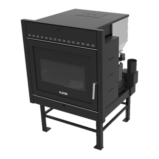
Approved Document J. Health and Safety Care must be taken when installing a Klover pellet appliance to ensure that the requirements of the Health and Safety at Work Act are met. Handling Adequate facilities must be available for loading, unloading and site handling the appliance bearing in mind the weight of the appliance. - Page 8 PELLET INSERT STOVE PELLET FIRE PLACE 22, PELLET FIRE PLACE 240 GLASS EN - Rev. 2.1 RIGHT SIDE TECHNICAL COMPARTMENT Manometer (indicates the pressure of the heating system). Terminal for room thermostat connection. Anti-interference filter connection for power Flue gas outlet.
-
Page 9: Overall Dimensions
PELLET INSERT STOVE PELLET FIRE PLACE 22, PELLET FIRE PLACE 240 GLASS EN - Rev. 2.1 Overall dimensions... -
Page 10: Connections Data Sheet
PELLET INSERT STOVE PELLET FIRE PLACE 22, PELLET FIRE PLACE 240 GLASS EN - Rev. 2.1 Connections data sheet WALL SET-UP REAR VIEW Description of connections M = System delivery (measures hose connections supplied) 3/4" M R = System return (measures hose connections supplied) 3/4"... -
Page 11: Technical Specifications
PELLET INSERT STOVE PELLET FIRE PLACE 22, PELLET FIRE PLACE 240 GLASS EN - Rev. 2.1 Technical Specifications Nominal heat input kW (Kcal/h) 25,4 (20.650) Reduced thermal capacity kW (Kcal/h) 7,0 (6.000) Nominal thermal output kW (Kcal/h) 24,0 (20.650) Reduced thermal power kW (Kcal/h) 6,7 (5.750) -
Page 12: Pellet Properties
PELLET INSERT STOVE PELLET FIRE PLACE 22, PELLET FIRE PLACE 240 GLASS EN - Rev. 2.1 Pellet properties The appliance has been tested with all types of pellets available on the market. The pellets must have the following properties: - Diameter 6 mm. - Page 13 PELLET INSERT STOVE PELLET FIRE PLACE 22, PELLET FIRE PLACE 240 GLASS EN - Rev. 2.1 The unit must be installed on a floor with a suitable load capacity. If the existing building does not fulfil this requirement appropriate measures (e.g. load distribution plate) must be taken.
-
Page 14: Spaces Around And Above The Appliance
PELLET INSERT STOVE PELLET FIRE PLACE 22, PELLET FIRE PLACE 240 GLASS EN - Rev. 2.1 Spaces around and above the appliance The figure below indicates the minimum measurements to be respected when positioning the insert with respect to the walls and/or the two "covering"... - Page 15 PELLET INSERT STOVE PELLET FIRE PLACE 22, PELLET FIRE PLACE 240 GLASS EN - Rev. 2.1 Fig. 1 AIR VENT DIAMETER 150mm If it is not possible to put an air vent in the wall behind the appliance, make a hole in a perimeter wall in the room where it is installed and another hole in the covering (see example in Fig.
-
Page 16: The Flue Pipe And Connection To The Same
PELLET INSERT STOVE PELLET FIRE PLACE 22, PELLET FIRE PLACE 240 GLASS EN - Rev. 2.1 The UNI 10683 Standard FORBIDS the drawing of combustion air from garages, warehouses storing combustible materials, or from business premises with a fire hazard. -
Page 17: Chimney
PELLET INSERT STOVE PELLET FIRE PLACE 22, PELLET FIRE PLACE 240 GLASS EN - Rev. 2.1 - Every direction change must be carried out with a T-shaped fitting and inspection cap. The tubes must be air tight through special seals which resist up to 250° C. Attach the pipes to the wall with special collars to avoid any vibration. -
Page 18: Electrical Connection
Do not pass electric cables in the immediate vicinity of the flue gas pipe, unless they are insulated with suitable materials. KLOVER srl declines all responsibility for injury to persons and animals or damage to objects due to failure to connect the appliance to earth or to comply with IEC specifications. -
Page 19: Control Of A Possible Three-Way Motorised Valve For The Dhw System (On Prepared Models Only)
PELLET INSERT STOVE PELLET FIRE PLACE 22, PELLET FIRE PLACE 240 GLASS EN - Rev. 2.1 Control of a possible three-way motorised valve for the DHW system (on prepared models only) The pellet appliance is equipped as standard with a control for a possible 3-way motorised valve to be installed on the domestic water circuit (for prepared models only). -
Page 20: Connection To The Room Thermostat
PELLET INSERT STOVE PELLET FIRE PLACE 22, PELLET FIRE PLACE 240 GLASS EN - Rev. 2.1 Connection to the room thermostat On the back of the appliance there is a bridged terminal which is used to connect the environment thermostat that will command the operation. -
Page 21: The Display
PELLET INSERT STOVE PELLET FIRE PLACE 22, PELLET FIRE PLACE 240 GLASS EN - Rev. 2.1 In the event of water with hardness exceeding 28 °f, an anti-limescale device must be installed. This must be selected on the basis of the specific properties of the water. - Page 22 PELLET INSERT STOVE PELLET FIRE PLACE 22, PELLET FIRE PLACE 240 GLASS EN - Rev. 2.1 The following figure describes the meanings of the status signals appearing on the display left side (1st LED SERIES). ROOM THERMOSTAT: the LED is on when the thermostat contact is open.
-
Page 23: The Menu
PELLET INSERT STOVE PELLET FIRE PLACE 22, PELLET FIRE PLACE 240 GLASS EN - Rev. 2.1 The table explains how the buttons on the display work. DESCRIPTION MODE ACTION Programming mode.. Changes/increases the value of the selected menu item. Increase temperature (1) Working/off.. - Page 24 PELLET INSERT STOVE PELLET FIRE PLACE 22, PELLET FIRE PLACE 240 GLASS EN - Rev. 2.1 Menu 02 – Set chrono Sub-menu 02 – 01 – Enable chrono Allows you to globally enable and disable all programmable thermostat functions. For the correct operation it is recommended to enable it (“ON”) when at least one on/off programme (daily, weekly or weekend programme) is...
- Page 25 PELLET INSERT STOVE PELLET FIRE PLACE 22, PELLET FIRE PLACE 240 GLASS EN - Rev. 2.1 PROGRAM 3 MENU LEVEL SELECTION MEANING POSSIBLE VALUES 02 – 03 – 20 START PROG-3 Turn-on time of the third programme Time – OFF 02 –...
- Page 26 (detected with KLOVER “Remote control”) is reached..to control the appliance with both the KLOVER “Remote control” room temperature and the boiler thermostat: - enable the room sensor on the “Remote control” (Stove settings menu +> Enable room sensor -> ON) - enable the boiler thermostat contact on the display of the appliance (Menu 4 - Enable contact ->...
-
Page 27: Initial Start-Up
PELLET INSERT STOVE PELLET FIRE PLACE 22, PELLET FIRE PLACE 240 GLASS EN - Rev. 2.1 Summary: REMOTE CONTROL MENU 04 – ENABLE R.T. CASE ACTION ROOM SENSOR CONTACT It works with room thermostat contact. It works with room thermostat contact. -
Page 28: Pellet Loading And Connection To The Mains Power Supply
PELLET INSERT STOVE PELLET FIRE PLACE 22, PELLET FIRE PLACE 240 GLASS EN - Rev. 2.1 The system and the water inside the boiler can be emptied by opening the “boiler body and system drain cock” situated at the back of the appliance. -
Page 29: Working Mode
PELLET INSERT STOVE PELLET FIRE PLACE 22, PELLET FIRE PLACE 240 GLASS EN - Rev. 2.1 Working mode During the working phase, by pressing 1, you can set the “SET H2O” (maximum water temperature in the boiler). When this temperature is reached, the appliance enters economy mode operation “T-H2O ECONOMY”. -
Page 30: Problems, Alarms, Useful Advices
PELLET INSERT STOVE PELLET FIRE PLACE 22, PELLET FIRE PLACE 240 GLASS EN - Rev. 2.1 - Room Temperature (used only in case of the “Remote control” connection) To modify the ambient temperature, simply select “SET ROOM TEMP” by pressing button 2. Now use buttons 1 and 2. -
Page 31: What Happens If
PELLET INSERT STOVE PELLET FIRE PLACE 22, PELLET FIRE PLACE 240 GLASS EN - Rev. 2.1 What happens if… …the pellets do not ignite If the ignition fails, the display will show the alarm message “NO IGNIT ALLARM”. Cancel the alarm and reset the appliance to standard condition by pressing button 4 for a few seconds. -
Page 32: Alarm Signals
PELLET INSERT STOVE PELLET FIRE PLACE 22, PELLET FIRE PLACE 240 GLASS EN - Rev. 2.1 Alarm signals The following table describes the different alarms which may appear. DISPLAY VISUALISATION ORIGIN OF ALARM Black-out alarm. When power is cut off under determined conditions (see“What... -
Page 33: Non-Routine Cleaning
PELLET INSERT STOVE PELLET FIRE PLACE 22, PELLET FIRE PLACE 240 GLASS EN - Rev. 2.1 Empty the ash drawer (figure Thoroughly clean the brazier from combustion residues by taking it out from its position and removing any residues inside... - Page 34 PELLET INSERT STOVE PELLET FIRE PLACE 22, PELLET FIRE PLACE 240 GLASS EN - Rev. 2.1 Remove the two sides of the flue gas pass and clean the combustion chamber well (figures 4 and After having removed the ash drawer, extract the underlying base (right and left)
-
Page 35: Monthly Cleaning
PELLET INSERT STOVE PELLET FIRE PLACE 22, PELLET FIRE PLACE 240 GLASS EN - Rev. 2.1 To ensure correct operation, it is necessary to remove the sawdust deposited on the running guides (figure 9) and on the base of the tank (figure 10) at least once every 15 days. -
Page 36: Cleaning The Ceramic Glass
You must periodically check the seals because the latter guarantee the air- and water-tightness of the appliance and its good functioning; if they are worn or damaged you need to be replace them immediately by contacting a Klover Authorised technical assistance centre. -
Page 37: Pcb Parameters
The following parameters are already stored during the testing of the appliance directly in the factory; these parameters are the result of special tests using several types of pellets and must not be changed without the authorisation of Klover srl so as not to impair the operation of the appliance. - Page 38 PELLET INSERT STOVE PELLET FIRE PLACE 22, PELLET FIRE PLACE 240 GLASS EN - Rev. 2.1 THRESHOL Pr14 M – 9 – 6 – 14 Flue gas maximum temperature °C 110 – 250 MAXIMUM Flue gas temperature threshold for starting the Pr15 M –...
-
Page 39: Wiring Diagram
PELLET INSERT STOVE PELLET FIRE PLACE 22, PELLET FIRE PLACE 240 GLASS EN - Rev. 2.1 WIRING DIAGRAM CABLE 4 x 0,75 (OPTIONAL) THREE-WAY CONNECTION LEGEND: FOR MOTORISED THREE-WAY BLUE = COMMON VALVE CONNECTION BLACK = OPENING PHASE BROWN =CLOSING PHASE... -
Page 40: Warranty Conditions
- A copy of the initial start-up report issued by the Authorised Technical Assistance Centre must be preserved along with the proof of purchase receipt. - KLOVER s.r.l. disclaims any liability for accidents resulting from failure to comply with the instructions contained the user and maintenance manual attached to the appliance. - Page 41 PELLET INSERT STOVE PELLET FIRE PLACE 22, PELLET FIRE PLACE 240 GLASS EN - Rev. 2.1...
- Page 42 PELLET INSERT STOVE PELLET FIRE PLACE 22, PELLET FIRE PLACE 240 GLASS EN - Rev. 2.1...
- Page 43 PELLET INSERT STOVE PELLET FIRE PLACE 22, PELLET FIRE PLACE 240 GLASS EN - Rev. 2.1...
- Page 44 Cod. CS.IST.PFP22-EN KLOVER Srl Via A. Volta, 8 37047 San Bonifacio (VR) P.IVA 02324280235 www.klover.it...
Need help?
Do you have a question about the PELLET FIRE PLACE 240 GLASS and is the answer not in the manual?
Questions and answers