Table of Contents
Advertisement
Quick Links
Advertisement
Table of Contents

Related Manuals for SUTO S110-P-V2


Summary of Contents for SUTO S110-P-V2
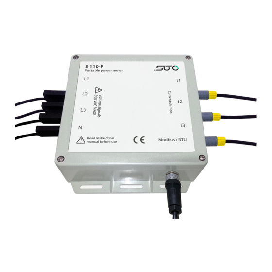
- Page 1 English Instruction and operation manual S110-P-V2 Power Meter...
- Page 2 The device is destined exclusively for the described application. SUTO offers no guarantee for the suitability for any other purpose. SUTO is also not liable for consequential damage resulting from the delivery, capability or use of this device.
-
Page 3: Table Of Contents
7.1.3 1-phase / 2-wire connection..........10 7.2 Electrical connection.............11 7.2.1 Connection to S551 ............11 7.2.2 Connection to the Rogowski coils........13 7.2.3 Connection to the Voltage leads........14 8 Optional extra accessories............15 8.1 Extra accessories for S110-P..........15 9 Maintenance................15 10 Disposal or waste..............15 S110-P-V2... -
Page 4: Safety Instructions
• Do not exceed the permitted operating parameters. • Make sure the product is operated in its permitted limitations. • Do not exceed or undercut the permitted storage and operation temperature. • The product should be maintained frequently, at least annually. S110-P-V2... -
Page 5: Registered Trademarks
• Avoid direct UV and solar radiation during storage. • For the storage the humidity has to be <90%, no condensation. 2 Registered trademarks SUTO ® Registered trademark of SUTO iTEC MODBUS ® Registered trademark of the Modbus Organization, Hopkinton, USA HART ®... -
Page 6: Application
2500 kW (depends on Rogowski coil) Frequency range 50 / 60 Hz Sampling rate 8 k/sec Available clamp sensors Rogowski coil 1 ... 100 A 10 ... 1000 A 30 ... 3000 A Operating temperature -25 ... +55°C Storage temperature -40 ... +85°C S110-P-V2... -
Page 7: Electrical Data
0.5 % (1% ... 120% of rang) Power Factor 0.005 from 10 ... 120 % Frequency 0.01 % from 45 ... 65 Hz Active/Apparent Power IEC62053-22 Class 0.5 Reactive Power IEC62053-21 Class 2 Active Energy IEC62053-22 Class 0.5 s Reactive Energy IEC62053-21 Class 2 S110-P-V2... -
Page 8: Dimensional Drawing (In Mm)
6 Dimensional drawing (in mm) 6 Dimensional drawing (in mm) S110-P-V2... -
Page 9: Installation
3000A = S554 0161 100A = S554 0162 Test leads No P/N Test clips No P/N 5 m cable with connector to S551. A553 0111 Instruction manual No P/N 7.1 Voltage and current connection 7.1.1 3-phase / 4-wire connection S110-P-V2... -
Page 10: 3-Phase / 3-Wire Connection
7 Installation 7.1.2 3-phase / 3-wire connection 7.1.3 1-phase / 2-wire connection S110-P-V2... -
Page 11: Electrical Connection
3. Press the “Menu” button on the interface of S551 and select the sensor type of clamp current sensor. For this please have a look at the picture below. 4. Press Save when you have changed the settings. 5. go back to "Home” S110-P-V2... - Page 12 7 Installation 6. By pressing the “Value” button the online view will be shown. Use the arrows to see all windows. S110-P-V2...
-
Page 13: Connection To The Rogowski Coils
7 Installation 7.2.2 Connection to the Rogowski coils Please observe the following steps to connect the coils. 1. Place the coil's around the isolated conductor. 2. Take care of current orientation, There is an arrow on body to indicate direction. S110-P-V2... -
Page 14: Connection To The Voltage Leads
Typical connection for the S110-P: 7.2.3 Connection to the Voltage leads For S110-P connect the voltage leads (L1, L2, L3 and N) to the 3 phase conductors. Connect N if a 4-wire connection is required. S110-P-V2... -
Page 15: Optional Extra Accessories
The sensor, the accessories and its packings must be disposed according to your local statutory requirements. The dispose can also be carried by the manufacturer of the product, for this please contact the manufacturer. S110-P-V2... - Page 16 SUTO iTEC GmbH SUTO iTEC (ASIA) Co., Ltd. Grißheimer Weg 21 Room 10, 6/F, Block B, Cambridge Plaza D-79423 Heitersheim 188 San Wan Road, Sheung Shui, N.T. Germany Hong Kong Tel: +49 (0) 7634 50488 00 Tel: +852 2328 9782...
Need help?
Do you have a question about the S110-P-V2 and is the answer not in the manual?
Questions and answers