
Related Manuals for SUTO S120-Ambient


Summary of Contents for SUTO S120-Ambient
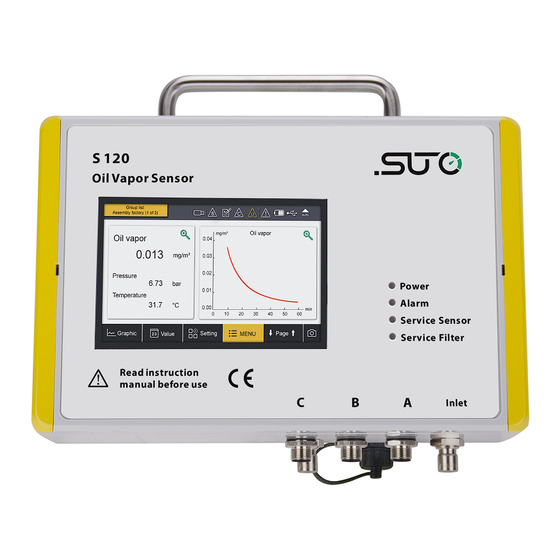
- Page 1 English Instruction and Operation Manual S120-Ambient Oil Vapor Monitor for Ambient Measurement...
- Page 2 The device is designed exclusively for the described application. SUTO offers no guarantee for the suitability for any other purpose. SUTO is also not liable for consequential damage resulting from the delivery, capability or use of this device.
-
Page 3: Table Of Contents
7.4.1 Pin assignment of M12 connectors........17 7.4.2 Connection to the power supply ........17 7.4.3 RS-485 networking (Modbus/RTU)........17 7.4.4 TCP/IP networking (Modbus/TCP)........17 7.4.5 Connection to the SUTO display units.......18 8 Configuration ................19 8.1 Local display...............19 8.2 Service kit (optional) ............19 9 Operations using the integrated display........20 9.1 User interface ..............20... - Page 4 10 Troubleshooting...............30 10.1 LED indicators..............30 10.2 Error indications..............31 11 Signal outputs.................32 11.1 Analog output ..............32 11.2 Modbus/RTU output............32 11.3 Modbus/TCP output............34 11.4 Alarm output ..............34 12 Calibration................35 13 Maintenance................36 14 Disposal or waste..............36 S120-Ambient...
-
Page 5: Safety Instructions
• Any electrical work on the system is only allowed by authorized qualified personal. ATTENTION! Permitted operating parameters! Observe the permitted operating parameters, any operation exceeding this parameters can lead to malfunctions and may lead to damage on the instrument or the system. S120-Ambient... - Page 6 • Please make sure that the storage temperature of the device is between -20 ... +50°C. • Avoid direct UV and solar radiation during storage. • For the storage the humidity must be <90%, no condensation. S120-Ambient...
-
Page 7: Registered Trademarks
2 Registered trademarks 2 Registered trademarks SUTO ® Registered trademark of SUTO iTEC MODBUS ® Registered trademark of the Modbus Organization, Hopkinton, USA HART ® Registered trademark of the HART Communication Foundation, Austin, USA Android™, Trademarks of Google LLC Google Play... -
Page 8: Application
• PID sensor for the highest accuracy. • Service and alarm indication through LEDs. • Connectable to display and data logger of SUTO as well as third- party display and control units. • IP65 casing provides robust protection in rough industrial environment. -
Page 9: Technical Data
5” graphic display with touch interface and data logger Interface USB, Modbus/RTU (RS-485), Modbus/TCP (Ethernet) Weight 2.4 kg UV lamp lifetime 6,000 working hours or 1 year, whichever comes first 5.2 Electrical data Power supply 24 VDC ± 5%, 10 W S120-Ambient... -
Page 10: Output Signals
5.3 Output signals Analogue output 4 ... 20 mA Digital output RS-485, Modbus/RTU Ethernet, Modbus/TCP Alarm output Relay, NO, 40 VDC, 0.2 A 5.4 Accuracy Accuracy 5% of reading ± 0.003 mg/m 6 Dimensional drawings Dimensional drawings of S120-Ambient in mm S120-Ambient... - Page 11 6 Dimensional drawings Dimensional drawing of the funnel with stand in mm S120-Ambient...
-
Page 12: Installation
Instruction manual Calibration certificate 7.1 Installation requirements The S120-Ambient can be used as a portable device or fixedly installed. The device is not suitable for permanent outside installations. Use always the supplied stand to place the funnel in the ambient and make sure the area in front of the funnel is free of any obstacles which could lead to wrong measurements. - Page 13 7 Installation Method 1. Method 2. S120-Ambient...
-
Page 14: Air Connections
7 Installation 7.3 Air connections The air inlet and outlet are located at the bottom of the S120-Ambient, as shown below. Follows the steps to connect the S120-Ambient with the funnel for air collection. 1. Connect the hose to the inlet of the S120-Ambient. - Page 15 7 Installation Please consider the following recommendations for a successful measurement result: • All components from the sampling point to the S120-Ambient must be oil- and grease-free. • Ambient and gas temperature must be within the specified ranges stated in section 5.1 General...
-
Page 16: Electrical Connections
7 Installation 7.4 Electrical connections The S120-Ambient provides five electrical connectors, as shown in the following figure. Connectors Description Three M12 connectors • To connect to the power supply (labeled as “A”, ”B”, and ”C”) • To connect to the RS-485 network (Modbus/RTU) •... -
Page 17: Pin Assignment Of M12 Connectors
7.4.3 RS-485 networking (Modbus/RTU) When output signal is carried over the Modbus/RTU protocol, connect the S120-Ambient to the RS-485 network through the M12-A or M12-C connector. 7.4.4 TCP/IP networking (Modbus/TCP) When the Modbus/TCP protocol is applied, connect the S120-Ambient to the TCP/IP network through the RJ-45 connector. -
Page 18: Connection To The Suto Display Units
7 Installation Remove the protection cap and plug in the network cable (RJ-45). 7.4.5 Connection to the SUTO display units S120-Ambient Color S330/S331 S320 code Signal Terminal Terminal brown A.2 / B.2 white A.3 / B.3 blue black grey brown brown A.2 / B.2... -
Page 19: Configuration
Transmission mode = RTU Modbus Device address = last two digits of the serial number IP Configuration = DHCP You can use one of the following ways to configure S120-Ambient. 8.1 Local display See Chapter 9 Operations using the integrated display. -
Page 20: Operations Using The Integrated Display
9 Operations using the integrated display 9 Operations using the integrated display The S120-Ambient is equipped with an integrated display, you can configure the device by using the display. This chapter describes the usage of the display and provides instructions on how to configure the device. -
Page 21: Quick Buttons
Description of icons displayed in the status bar. USB stick connected System error Sensor connection has Sensor unit is not changed, not matching matching with with configuration configuration RTC backup battery Logger status status Sensor calibration is Alarm triggered expired S120-Ambient... -
Page 22: Main Menus
After you click the Menu button, the following screen appears displaying all operating menus. The main menus and their functions are described below. Sensor settings To view and check the S120-Ambient settings. Location setting Settings are fixed. Logger To view and change S120-Ambient data logger settings. -
Page 23: Sensor Settings
RS-485. 9.3 Sensor settings To configure sensor settings before starting measurement. After you changes settings, click “Save” to have the changes saved in the S120-Ambient. 9.3.1 Basic setting Altitude Enter the Altitude. To obtain an accurate oil vapor measurement, you must input your altitude. -
Page 24: Analog Output
9.3.2 Analog output To configure the scaling of analog output. Whenever the output unit is changed, it is recommended to adjust the scaling of the analog output. 9.3.3 Alarm settings To configure the threshold of oil vapor that triggers the alarm. S120-Ambient... -
Page 25: Status
9.4 Logger settings To view and change the logger settings and status. Start time Logger start time Sample / Channel Recorded sample number per logging channel Logger channel Total recording channel number Sample rate Recording interval Status Logger status S120-Ambient... -
Page 26: Files
(USB OTG Drive) or can be transferred to a PC using the supplied USB cable and the software S4A. 9.5 Files To view and manage all recorded measurement files and screenshots. To view the available memory. 9.6 Service info To view the contact information of the company that provides the service. S120-Ambient... -
Page 27: System Settings
9 Operations using the integrated display 9.7 System settings To view and change S120-Ambient system-level settings. Password To set the password to protect some critical operations from unauthorized access. Back light To adjust brightening and dimming time out. Calibrate touch... -
Page 28: Communication
9 Operations using the integrated display 9.8 Communication To configure the field bus RS-485 and Ethernet Modbus/TCP. 9.8.1 Modbus/RTU settings To change the Modbus/RTU settings. S120-Ambient... -
Page 29: Modbus/Tcp Settings
9 Operations using the integrated display 9.8.2 Modbus/TCP settings To change the Modbus/TCP settings. S120-Ambient... -
Page 30: Troubleshooting
10 Troubleshooting 10 Troubleshooting This chapter describes how to troubleshoot S120-Ambient based on error indications such as LED indicators, relay status, and current output. 10.1 LED indicators Indicates the power status. Indicates the alarm status. Indicates whether the sensor need to be serviced. -
Page 31: Error Indications
10 Troubleshooting 10.2 Error indications This table lists the main error indications with S120-Ambient and the corresponding instructions to locate and fix errors. When the alarm LED is on, 1. Measure the current output and relay status. 2. Refer to the following table to proceed. -
Page 32: Signal Outputs
11 Signal outputs 11 Signal outputs 11.1 Analog output The S120-Ambient has an analog output range of 4 ... 20 mA. This output is scaled to: • 4 mA = 0.000 mg/m • 20 mA = 10.000 mg/m 11.2 Modbus/RTU output The following table lists specifications of the Modbus/RTU output channels in this sensor. - Page 33 10 Temperature too low Calibration overdue 11 Temperature too high Sensor life time will overdue 12 Inner communication failed soon Sensor overdue 13 Sensor signal is too small Filter will overdue soon 14 Sensor signal is too high Filter overdue S120-Ambient...
-
Page 34: Modbus/Tcp Output
UINT32_L 4-byte number (sensor) 11.4 Alarm output The S120-Ambient provides a relay alarm output. This output enables you to monitor such as the oil vapor content and gives an alarm at a particular threshold value. Alarm relay specifications: Rating: 40 VDC / 0.2 A... -
Page 35: Calibration
Parameters such as oil, high humidity or other impurities can affect the calibration and furthermore the accuracy. We recommend to calibrate the instrument at least once per year. The calibration is excluded from the instruments warranty. To request the calibration service, please contact the manufacturer. S120-Ambient... -
Page 36: Maintenance
The dispose can also be carried by the manufacturer of the product, for this please contact the manufacturer. SUTO iTEC GmbH SUTO iTEC (ASIA) Co., Ltd. Grißheimer Weg 21 Room 10, 6/F, Block B, Cambridge Plaza D-79423 Heitersheim 188 San Wan Road, Sheung Shui, N.T.
Need help?
Do you have a question about the S120-Ambient and is the answer not in the manual?
Questions and answers