Table of Contents
Advertisement
Quick Links
Advertisement
Table of Contents

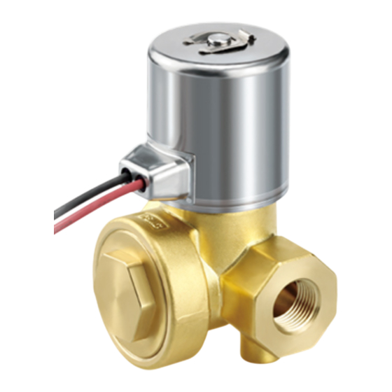
Summary of Contents for SMC Networks JSXH31-CP X2 Series
- Page 1 JSXH31-CP***-**-*-X2...
-
Page 2: Table Of Contents
Contents Contents……………………………………………………………………………..P1 Safety Instructions………………………………………………………………….P2,3 1. Precautions for Design….…………………………………………………….P4 2. Operating Environment.………………………………………………………P5 3. Precautions for Fluid.…………………………………………………………P5 4. Fluid Quality…..………………………………………………………………..P6 5. Installation………………………………………………………………………P6 6. Piping……………………………………………………………………………P6, 7 7. Wiring……………………………………………………………………………P8 8. Electrical Connection………………………………………………………….P9,10 9. Electric Circuit………………………………………………………………….P10,11 10. Maintenance and Inspection………………………………………………….P11 11. Replacement Parts…………………………………………………………….P11 12. Return of Product………………………………………………………………P11 13.... -
Page 3: Safety Instructions
Metso Valve Controller Safety Instructions These safety instructions are intended to prevent hazardous situations and/or equipment damage. These instructions indicate the level of potential hazard with the labels of “Caution,” “Warning” or “Danger.” They are all important notes for safety and must be followed in addition to International Standards (ISO/IEC) , and other safety regulations. - Page 4 Metso Valve Controller Safety Instructions Limited warranty and Disclaimer/Compliance Requirements The product used is subject to the following “Limited warranty and Disclaimer” and “Compliance Requirements”. Read and accept them before using the product. Limited warranty and Disclaimer Scope of Warranty : Warranty shall be granted for non-conformity of the Company’s product (“Product”) to the relevant specifications.
-
Page 5: 1. Precautions For Design
1.Precautions for Design Warning 1. Check the specifications. Fully understand the applications, fluids, environment, and other operating conditions to use this product within the specified range. Operation outside of the product operating range may cause it to be damaged or malfunction. SMC does not guarantee against any damage if the product is used outside of the specification range. -
Page 6: 2. Operating Environment
2.Operating Environment Warning Do not use this product at any of the following locations. 1) Location where the product may be exposed to an atmosphere containing steam, corrosive fluid (chemicals), seawater, or water. Even on a product with a protection classification (IP65, IP67), take appropriate protective measures in an environment where it is exposed to water for a long time. -
Page 7: 5. Installation
4.Quality of Fluid Warning Water Operation failure due to the rust transferred from the piping or chloride flowing in the piping may result in the breakage of the product. When the product is broken, fluids or components might be scattered. Therefore, install an appropriate protective measure. - Page 8 Wrapping of sealant tape When screwing pipes or fittings into ports, ensure that chips from the pipe threads and sealing material does not enter the valve. When using sealant tape, leave 1.5 to 2 thread ridges exposed at the end of the threads. Screwing-in of pipe and fitting When connecting a pipe to the valve, tighten it within the allowable torque range below.
- Page 9 . . : : - 8 -...
-
Page 10: Wiring
DIN terminal Disassembly Loosen the binding head screw with the flange, pull the housing up in the arrow direction to remove the solenoid valve from the connector. Pull out the binding head screw with the flange from the housing. Insert a small flat blade screwdriver to the notch at the bottom of the terminal block, and then remove the terminal block from the housing. -
Page 11: 9. Electric Circuit
M12 connector 1. IP67 (enclosure) of the valve can be obtained by using a female connector (with cable) compliant with IP67. Note that the product cannot be used underwater. 2. Mounting the connector using tools may break the connector. Securely tighten the connector by hand. -
Page 12: 10. Maintenance And Inspection
10.Maintenance and Inspection Warning Removal of product Shut off the fluid supply source and release the fluid pressure in the system. Shut off the power supply. Confirm that the valve temperature has dropped sufficiently, and then remove the product. Operation at low frequency Perform switching of the valve at least once every 30 days to prevent malfunction. -
Page 13: 13. Models
13.Models How to order - 12 -... -
Page 14: 14. Specifications
14.Specifications 15.Construction - 13 -... -
Page 15: 16. Definition And Terminology
16.Definition and Terminology This shows the maximum pressure difference (difference between inlet Maximum pressure and outlet pressure) that is allowed for operation. When the operating pressure downstream side pressure is 0 MPa, this becomes the maximum differential operating pressure. Minimum This shows the minimum pressure difference (difference between inlet operating pressure pressure and outlet pressure) that is required for the main valve to be... - Page 16 18. Trouble Check Sheet (target series: JSXH31P-CP***-**-*-X2) Operating conditions Deliver date YY/MM/DD Operating period XX months Accumulated Approx. ____ cycles operating cycles Warranty period: Within 1.5 years after the product is delivered or 1 year in service Please refer to and use this trouble check sheet as a diagnosis check sheet for early solution in the event of trouble. Symptom Possible cause Confirmation of condition...
- Page 17 Symptom Possible cause Confirmation of condition Countermeasures Is there any abnormality such as failure in the power There is a possibility of abnormality in the power supply, control supply and control circuit? circuit, or wiring system. □ → Is there any abnormality, such as disconnection of 1) Replace or repair the power supply, control circuit, or wiring Power supply wiring system and erroneous wiring?
- Page 18 Symptom Possible cause Confirmation of condition Countermeasures Is the fluid temperature or ambient temperature There is a possibility that a rubber seal part has been deteriorated □ □ → above the upper limit of the operating temperature due to high temperature. Leakag range? 1) Use this product within the operating temperature range.
- Page 19 Revision history 4-14-1, Sotokanda, Chiyoda-ku, Tokyo 101-0021 JAPAN Tel: + 81 3 5207 8249 Fax: +81 3 5298 5362 https://www.smcworld.com Note: Specifications are subject to change without prior notice and any obligation on the part of the manufacturer. © SMC Corporation All Rights Reserved...


Need help?
Do you have a question about the JSXH31-CP X2 Series and is the answer not in the manual?
Questions and answers