Table of Contents
Advertisement
Available languages
Available languages
Quick Links
1.0 Introduction ............................................................. 3
1.1 General Information ................................................ 3
1.2 Required Components ............................................. 3
1.3 Installation Information ........................................... 3
1.4 Kozy Power Vent Dimensions .................................. 4
1.5 Unit Specific Requirements ..................................... 5
2.0 Venting ..................................................................... 6
2.1 Venting Requirements ............................................. 6
2.2 Draft Bypass Adjustment ......................................... 8
3.0 Termination Locations .............................................. 9
4.0 Framing and Clearances ......................................... 10
4.1 Framing Dimensions .............................................. 10
4.2 Clearances to Combustibles .................................. 10
4.3 Rooftop Termination ............................................. 11
5.0 Finishing Materials ................................................. 12
Materials ................................................................ 12
Than 1" Thick ......................................................... 12
6.0 Installations ........................................................... 13
6.1 Installing Vent Cap ................................................. 13
6.2 Installing Vent Pipe ................................................ 15
6.3 Installing Power Vent Wire Harness ...................... 16
7.0 Electrical Information for Installation ..................... 20
7.1 Wiring to the Appliance ......................................... 20
8.0 Maintenance .......................................................... 22
8.1 Replace Fan Assembly ........................................... 22
8.2 Replace Vacuum Switch ......................................... 23
9.0 Troubleshooting ..................................................... 25
10.0 Replacement Parts ................................................. 27
IMPORTANT: Failure to read and follow these instructions
may create a possible hazard and will void the fireplace
warranty.
KOZY POWER VENT #KPV
Kozy Power Vent Approved Fireplaces:
#ALP-36S, #BHM38, #BHM-44, #BHM-52, #CLW-40, #CLW-50,
#CLW-72, #CLW-ST, #NDK-41-DV
READ ALL THESE STEPS BEFORE STARTING INSTALLATION.
LEAVE TEHSE INSTRUCTIONS WITH THE APPLIANCE.
This kit must be installed by a qualified installer, service
agency, or gas supplier at the time of the heater installa-
tion. These instructions must be used in conjunction with
the installation and operation manual provided with the
appliance.
Please read all appliance owner's manual completely
before performing any procedures in these instructions.
English and French installation manuals are available through
your local dealer. Visit our website www.kozyheat.com.
Les manuels d'installation en français et en anglais sont dispo-
nibles chez votre détaillant local. Visitez www.kozyheat.com.
INSTALLER: Leave this manual with the appliance.
CONSUMER: Retain this manual for future reference.
1
Rev. 11 - May 2023
Advertisement
Chapters
Table of Contents

Related Manuals for kozy heat ALP-36S


Summary of Contents for kozy heat ALP-36S
-
Page 1: Table Of Contents
KOZY POWER VENT #KPV Kozy Power Vent Approved Fireplaces: #ALP-36S, #BHM38, #BHM-44, #BHM-52, #CLW-40, #CLW-50, #CLW-72, #CLW-ST, #NDK-41-DV 1.0 Introduction ............. 3 1.1 General Information ..........3 1.2 Required Components ..........3 1.3 Installation Information ........... 3 1.4 Kozy Power Vent Dimensions ........4 1.5 Unit Specific Requirements ........ - Page 2 Rev. 11 — May 2023...
-
Page 3: Introduction
The S.I.T. Power Vent Control Module is required for #KPV The exit termination of mechanical draft systems shall not installation. Kozy Heat Fireplaces ship with a standard be less than seven feet above grade when located adja- (non-powervent) control module. -
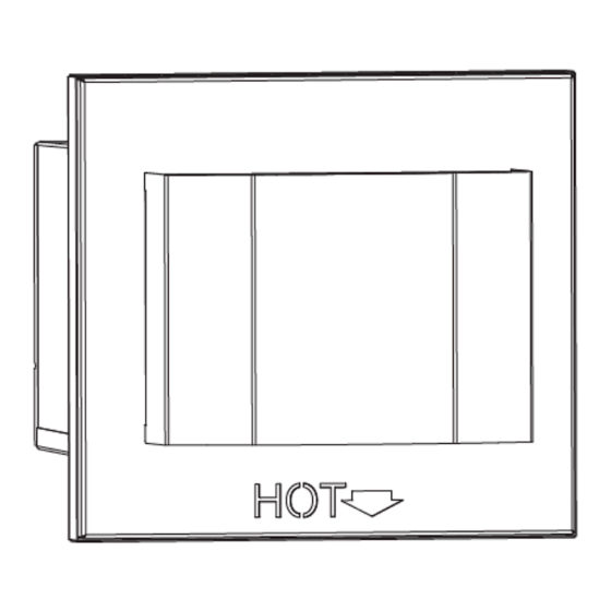
Page 4: Kozy Power Vent Dimensions
1.4 Kozy Power Vent Dimensions Figure 1.1 - #KPV Dimensions Rev. 11 — May 2023... -
Page 5: Unit Specific Requirements
Model #BHM-52 can have a 4" x 6-5/8" reducer right off the top of the appliance. • Model #ALP-36S can have a 4” x 6 - 5/8” reducer right • If your venting configuration has more vertical length off the top of the appliance. -
Page 6: Venting
2.0 Venting 2.1 Venting Requirements For information on standard procedures for venting the appliance, refer to the venting section of your specific ap- pliance installation manual. The #KPV is for use 4" x 6-5/8" coaxial rigid direct vent pipe. Depending on your appliance, the vent size must be reduced to 4"... - Page 7 Table 2.1 - KPV Venting Guidelines Maximum Elbows (8) 90° or (16) 45° Minimum Total Horizontal Vent Run Models #ALP-36S, #CLW-40, #CLW-50, #CLW-ST, #CLW-72, #NDK-41-DV: 6’ (1.8m) Models #BHM-38, #BHM-44, #BHM-52: 10’ (3m) Maximum Total Horizontal Vent Run 60’ (18.3m) Do not exceed 60’...
-
Page 8: Draft Bypass Adjustment
To adjust the draft bypass, loosen the locking screw. Adjust clock wise or counter clockwise depending on your specific installation. See Figures 2.4, 2.5, and 2.6. Table 2.2 - #ALP-36S, #BHM-38, #BHM-44, #BHM-52, #CLW-40, #CLW-50, #CLW-ST, #NDK-41-DV Draft Bypass Setting Chart Natural Gas... -
Page 9: Termination Locations
3.0 Termination Locations 3.1 Termination Cap Clearances Figure 3.1 - Minimum Termination Cap Clearances Canadian Installations US Installations Clearance above grade, veranda, porch, desk, or balcony. 12” (30cm) 12” (30cm) Clearance to window or door that may be opened 12” (30cm) 9”... -
Page 10: Framing And Clearances
4.0 Framing and Clearances 4.1 Framing Dimensions IMPORTANT: Framework for #KPV must be level • Dimensions are shown in Figure 4.1 to ensure precipitation does not build up inside the power vent unit. • Construct a framework as shown in Figure 4.2. Frame- work material should be the same dimensions as the material used for the wall framing. -
Page 11: Rooftop Termination
4.3 Rooftop Termination If the #KPV is going to terminate on a flat roof, an enclosure similar to the one shown in Figure 4.3 needs to be construction. Figure 4.3 - Roof top termination example Figure 4.4 - Termination Top Cleareance Figure 4.5 - Minimum Clearances for Rooftop Termination Rev. -
Page 12: Finishing Materials
5.0 Finishing Materials NOTE: If your installation has exterior finishing materials greater than 1" (25mm) thick, a #KPV-FEK Finishing Ex- tension Kit will be needed. The extension kit must be installed to allow for thicker exterior finishing materials for proper installation and fitting of the #KPV. IMPORTANT: IT IS IMPERATIVE THAT #KPV-FEK IS LEVEL TO ENSURE THE POWER VENT IS LEVEL. -
Page 13: Installations
6.0 Installation 6.1 Installing Vent Cap Remove the (4) screws securing the front cover to the Kozy Power Vent. Remove the eight screws securing the back assembly to the cap. See Figure 6.1. Slide the exhaust assembly out of the back of the cap. See Figure 6.2. - Page 14 Figure 6.6 - Secure Power Vent to Exterior Figure 6.5 - Silicone Backside Figure 6.7 - Installation to FEK Figure 6.8 - Installation to Exterior Wall Rev. 11 — May 2023...
-
Page 15: Installing Vent Pipe
6.2 Installing Vent Pipe • Refer to Section 2.0 Venting for vent requirements. • Apply a bead of the provided sealant around the inner exhaust pipe connection on the fireplace and the power vent as- sembly. See Figures 6.9 and 6.10. •... -
Page 16: Installing Power Vent Wire Harness
6.3 Installing Power Vent Wire Harness See Figure 6.13, Power Vent Internal Wiring on Page 17 for wiring schematic accompanying these instructions. Complete the necessary electrical preparation in Section 7.0 before connecting the wire harness to the fireplace. After mounting the wiring harness to the back assembly of the Kozy Power Vent in step #4 of Section 6.1 you will pro- ceed with wiring connections at the power vent. - Page 17 Figure 6.13 - Power Vent Internal wiring Rev. 11 — May 2023...
- Page 18 NOTE: Use Figure 7.4 (pg. 21) as wiring schematic refer- ences when following the individual instructions below. Next we are wiring the other end of the wire harness to the fireplace. Locate the power vent wire harness hole(s) on the fireplace. Your model may have one hole on one side of the fireplace, or one hole on ei- ther side of the fireplace.
- Page 19 Now we will connect the power vent wire harness to the control module and fireplace wire harness. The power vent wire harness has the black hot wire split with two female quick connections on either end. Plugs these into the black leads that have quick connections coming off the control module in the X12 combustion blower location.
-
Page 20: Electrical Information For Installation
7.0 Electrical Information for Installation 7.1 Wiring to the Appliance NOTE: Electrical wiring must be done in accordance with national, pro- vincial, and/or local electrical codes. WARNING: Disconnect electrical power from fireplace/power vent be- fore performing any maintenance, repair, or electrical wiring. NOTE: Electrical service of 120 VAC-60Hz must be supplied to the junc- tion box of the fireplace in order for the power vent to operate correct- ly. - Page 21 Figure 7.4 - Electrical Diagram Rev. 11 — May 2023...
-
Page 22: Maintenance
8.0 Maintenance WARNING: Before performing any maintenance or repair to the power vent assembly, make sure electrical power is disconnected to the fireplace. Vent System: Inspect all components and connections annu- ally. Replace, seal, or tighten pipe connections if necessary. Motor: the fan motor bearings are sealed and no further lubrication is necessary. -
Page 23: Replace Vacuum Switch
8.2 Replace Vacuum Switch NOTE: It may be easier to access and remove the vacuum switch by first removing the fan assembly as shown in Section 8.1. Remove (4) screws securing the front cover assembly and set aside. See Figure 8.1. Disconnect the vacuum tube from the fan assembly. - Page 24 Figure 8.7 - Fan Assembly Removal Figure 8.8 - Screws Securing Vacuum Switch Bracket Figure 8.9 - Vacuum Switch Removal Rev. 11 — May 2023...
-
Page 25: Troubleshooting
9.0 Troubleshooting Issue Cause Solution Pilot will not light Electrical power interrupted or Restore electrical power to appliance. disconnected Wiring disconnection Use wiring schematics in this manual to determine that all wiring connections are secure and correct. Gas supply turned off Check remote shut-off valves from the appliance. - Page 26 Issue Cause Solution Pilot and burner extinguish No propane in tank Check propane tank, refill if necessary. while in operation Incorrect glass assembly installation Adjust if necessary. See appliance installation manual. Incorrect vent cap installation Adjust if necessary. Vent cap blockage Remove debris if necessary.
-
Page 27: Replacement Parts
10.0 Replacement Parts Replacement parts are available through your local dealer. Contact your local dealer for availability and pricing. The following warning is for replacement parts for this appliance. ⚠ WARNING: This product can expose you to chemicals including Lead, which is [are] known to the State of California to cause cancer, birth defects P.O. - Page 28 Rev. 11 — May 2023...
- Page 29 KOZY POWER VENT #KPV Kozy Power Vent foyers approuvés: #ALP-36S, #BHM38, #BHM-44, #BHM-52, #CLW-40, #CLW-50, #CLW-72, #CLW-ST, #NDK-41-DV LISEZ TOUTES CES ÉTAPES AVANT DE COMMENCER L’INSTALLATION. 1.0 Introduction ............31 LAISSEZ CE MANUEL AVEC L’APPAREIL. 1.1 Informations générales.......... 31 Ce kit doit être installé par un centre de service ou un in- 1.2 Composants requis ..........
- Page 30 Rev. 11 — May 2023...
-
Page 31: Introduction
à une planification minutieuse lors de Le S.I.T. Le module de commande d'évent motorisé est l'installation du système. requis pour l'installation #KPV. Les foyers Kozy Heat sont livrés avec un module de commande standard (sans venti- 1.3.2 Directives d'installation lation). -
Page 32: Dimensions De L'évent Électrique Kozy
1.3.3 Exigences électriques Le #KPV fonctionne sur un service électrique de 120 VAC, 60 Hz qui est fourni à la boîte de jonction du foyer. La consomma- tion de courant de cet appareil est de 0,85 ampère. 1.3.4 Exigences de peinture Le #KPV peut être peint à... -
Page 33: Exigences Spécifiques À L'unité
Le modèle #BHM-52 peut avoir un réducteur de 4" x 6 -5/8" directement sur le dessus de l'appareil. • Le modèle #ALP-36S peut avoir un réducteur de 4" x 6 • Si votre configuration de ventilation a plus de lon- - 5/8"... -
Page 34: Ventilation
2.0 Ventilation 2.1 Exigences de ventilation Pour plus d'informations sur les procédures standard de ventilation de l'appareil, reportez-vous à la section de ven- tilation du manuel d'installation de votre appareil spécifique. Le #KPV est destiné à être utilisé avec un tuyau d'évent direct rigide coaxial de 4"... - Page 35 Tableau 2.1 - Directives de ventilation KPV Maximum Elbows (8) 90° or (16) 45° Course de ventilation horizontale Models #ALP-36S, #CLW-40, #CLW-50, #CLW-ST, #CLW-72, #NDK-41-DV: 6’ (1.8m) totale minimale Models #BHM-38, #BHM-44, #BHM-52: 10’ (3m) Course de ventilation horizontale 60’ (18.3m) Ne pas dépasser 60’...
-
Page 36: Réglage Du Brouillon De Brouillon
Voir les figures 2.4, 2.5 et 2.6. Tableau 2.2 - #ALP-36S, #BHM-38, #BHM-44, #BHM-52, #CLW- 40, #CLW-50, #CLW-ST, #NDK-41-DV Tableau de réglage de dérivation de tirage Figure 2.4 - Desserrer la vis de verrouillage... -
Page 37: Emplacements De Terminaison
3.0 Emplacements de terminaison 3.1 Dégagements du chapeau de terminaison Figure 3.1 - Dégagements minimaux du chapeau de terminaison Canadian Installations US Installations Dégagement au-dessus d'un terrain, véranda, galerie, terrasse ou balcon 12” (30cm) 12” (30cm) Dégagement à une porte ou fenêtre ouvrante 12”... -
Page 38: Encadrement Et Dégagements
4.0 Encadrement et dégagements 4.1 Dimensions de l'encadrement IMPORTANT : Le cadre pour #KPV doit être de • Les dimensions sont indiquées sur la figure 4.1 niveau pour s'assurer que les précipitations ne s'accumulent pas à l'intérieur de l'unité d'évacu- •... -
Page 39: Terminaison Sur Le Toit
4.3 Terminaison sur le toit Si le #KPV doit se terminer sur un toit plat, une enceinte similaire à celle illustrée à la Figure 4.3 doit être construite. Figure 4.3 - Exemple de terminaison sur le toit Figure 4.4 - Dégagement supérieur de résiliation Figure 4.5 - Dégagements minimaux pour la terminaison sur le toit Rev. -
Page 40: Matériaux De Finition
5.0 Matériaux de finition REMARQUE : Si votre installation comporte des maté- riaux de finition extérieurs de plus de 1 po (25 mm) d'épaisseur, un kit d'extension de finition #KPV-FEK sera nécessaire. Le kit d'extension doit être installé pour per- mettre des matériaux de finition extérieurs plus épais pour une installation et un ajustement corrects du #KPV. -
Page 41: Installations
6.0 Installation 6.1 Installation du capuchon d'aération 1. Retirez les (4) vis fixant le couvercle avant au Kozy Power Vent. 2. Retirez les huit vis fixant l'ensemble arrière au capuchon. Voir Figure 6.1. 3. Faites glisser l'ensemble d'échappement hors de l'arrière du capuchon. - Page 42 Figure 6.6 - Fixez l'évent électrique à l'extérieur Figure 6.5 - Dos en silicone Figure 6.7 - Installation sur FEK Figure 6.8 - Installation sur un mur extérieur Rev. 11 — May 2023...
-
Page 43: Installation Du Tuyau De Ventilation
6.2 Installation du tuyau de ventilation • Reportez-vous à la section 2.0 Ventilation pour les exigences de ventilation. • Appliquez un cordon du scellant fourni autour de la connexion intérieure du tuyau d'évacuation sur le foyer et l'ensem- ble d'évacuation forcée. Voir les figures 6.9 et 6.10. •... -
Page 44: Installation Du Faisceau De Câbles D'évent Motorisé
6.3 Installation du faisceau de câbles d'évent motorisé Voir Figure 6.13, Câblage interne de l'évent motorisé à la page 17 pour le schéma de câblage accompagnant ces instructions. Complétez la préparation électrique nécessaire à la section 7.0 avant de connecter le faisceau de câbles au foyer. Après avoir monté... - Page 45 Figure 6.13 - Câblage interne Rev. 11 — May 2023...
- Page 46 REMARQUE : Utilisez la Figure 7.4 (p. 21) comme schémas de câblage lorsque vous suivez les instructions individuelles ci- dessous. 3. Ensuite, nous câblerons l'autre extrémité du faisceau de câbles au foyer. Localisez le(s) trou(s) du faisceau de câbles de l'évent électrique sur le foyer. Votre modèle peut avoir un trou d'un côté...
- Page 47 Nous allons maintenant connecter le faisceau de câbles de l'évent électrique au module de commande et au faisceau de câbles du foyer. Le faisceau de câbles de ventilation électrique a le fil chaud noir divisé avec deux connexions rapides femelles à chaque extrémité. Branchez-les dans les fils noirs qui ont des connexions rapides sortant du module de com- mande à...
-
Page 48: Informations Électriques Pour L'installation
7.0 Informations électriques pour l'installation 7.1 Câblage à l'appareil REMARQUE : Le câblage électrique doit être effectué conformément aux codes électriques nationaux, provinciaux et/ou locaux. AVERTISSEMENT : Débranchez l'alimentation électrique du foyer/de l'évent avant d'effectuer tout entretien, réparation ou câblage élec- trique. - Page 49 Figure 7.4 - Schéma électrique Rev. 11 — May 2023...
-
Page 50: Entretien
8.0 Entretien AVERTISSEMENT : Avant d'effectuer tout entretien ou répa- ration de l'ensemble d'évacuation forcée, assurez-vous que l'alimentation électrique est débranchée du foyer. Système de ventilation : Inspectez tous les composants et connexions chaque année. Remplacer, sceller ou serrer les raccords de tuyauterie si nécessaire.. -
Page 51: Remplacer Le Vacuostat
8.2 Remplacer le vacuostat REMARQUE : Il peut être plus facile d'accéder à l'interrupteur à vide et de le retirer en retirant d'abord le ventilateur, comme indiqué à la section 8.1. Retirez les (4) vis fixant le capot avant et mettez-les de côté. Voir Figure 8.1. Débranchez le tube d'aspiration de l'assemblage du ventilateur. - Page 52 Figure 8.7 - Retrait de l'assemblage du ventilateur Figure 8.8 - Vis fixant le support de l'in- terrupteur à vide Figure 8.9 - Retrait du vacuostat Rev. 11 — May 2023...
-
Page 53: Dépannage
6.0 DEPANNAGE Problème Cause Solution La veilleuse ne Alimentation électrique interrompue ou Rétablir l’alimentation électrique du foyer. s’allume pas débranchée Câblage déconnecté À partir du schéma de câblage de ce manuel, vérifier que tous les câbles et fils sont connectés correctement et les connexions bien serrées. Alimentation de gaz fermée Vérifier les robinets d’arrêt manuels éloignés du foyer. - Page 54 Problème Cause Solution La veilleuse et le brûleur Réservoir de propane vide Vérifier le réservoir de propane. Remplir, au besoin. s’éteignent après avoir fonction- Installation incorrecte du cadre vitré Ajuster au besoin. Voir le manuel d’installation de l’appareil. né Installation incorrecte du chapeau d’évacu- Ajuster au besoin.
-
Page 55: Pièces De Rechange
10.0 Pièces de rechange Les pièces de rechange sont disponibles auprès de votre revendeur local. Con- tactez votre revendeur local pour connaître la disponibilité et les prix. L'aver- tissement suivant concerne les pièces de rechange de cet appareil. ⚠ AVERTISSEMENT : Ce produit peut vous exposer à des produits chimiques, y compris le plomb, qui est [sont] reconnus par l'État de Californie pour causer P.O. - Page 56 Rev. 11 — May 2023...
Need help?
Do you have a question about the ALP-36S and is the answer not in the manual?
Questions and answers