Table of Contents
Advertisement
Quick Links
Advertisement
Table of Contents

Related Manuals for Supermicro 7044H-T


Summary of Contents for Supermicro 7044H-T
- Page 1 UPER ® 7044H-T UPER ERVER 7044H-TR UPER ERVER USER’S MANUAL 1.0a...
- Page 2 Clara County in the State of California, USA. The State of California, County of Santa Clara shall be the exclusive venue for the resolution of any such disputes. Supermicro's total liability for all claims will not exceed the price paid for the hardware product.
-
Page 3: Preface
It provides information for the installation and use of the SuperServer 7044H- T/7044H-TR. Installation and maintainance should be performed by experienced technicians only. The SuperServer 7044H-T/7044H-TR is a high-end server based on the SC743T- 650/SC743T-R760 tower/4U rackmount chassis and the X6DHT-G, a dual processor serverboard that supports Intel speed of 800 MHz and up to 16/32 GB of registered ECC DDR333/266 SDRAM. - Page 4 UPER ERVER 7044H-T/7044H-TR User's Manual Chapter 4: System Safety You should thoroughly familiarize yourself with this chapter for a general overview of safety precautions that should be followed when installing and servicing the SuperServer 7044H-T/7044H-TR. Chapter 5: Advanced Serverboard Setup Chapter 5 provides detailed information on the X6DHT-G serverboard, including the locations and functions of connections, headers and jumpers.
- Page 5 Preface Notes...
-
Page 6: Table Of Contents
UPER ERVER 7044H-T/7044H-TR User's Manual Table of Contents Preface About This Manual ... iii Manual Organization ... iii Chapter 1: Introduction Overview ... 1-1 Serverboard Features ... 1-2 Server Chassis Features ... 1-3 Contacting Supermicro ... 1-6 Chapter 2: Quick Setup Overview ... - Page 7 Chapter 5: Advanced Serverboard Setup Handling the Serverboard ... 5-1 Processor and Heatsink Installation ... 5-2 Connecting Cables ... 5-4 Connecting Data Cables ... 5-4 Connecting Power Cables ... 5-4 Connecting the Control Panel ... 5-5 I/O Ports ... 5-6 Installing Memory ...
- Page 8 UPER ERVER 7044H-T/7044H-TR User's Manual Alarm Reset ... 5-17 Jumper Settings ... 5-17 Explanation of Jumpers ... 5-17 CMOS Clear ... 5-17 JLAN Enable/Disable ... 5-18 VGA Enable/Disable ... 5-18 Watch Dog Enable/Disable ... 5-18 Third Power Supply Alarm Enable/Disable ... 5-19 5-10 Onboard Indicators ...
- Page 9 Table of Contents Appendices: Appendix A: BIOS POST Codes ... A-1 Appendix B: Software Installation ... B-1 Appendix C: System Specifi cations ... C-1...
- Page 10 UPER ERVER 7044H-T/7044H-TR User's Manual Notes...
-
Page 11: Chapter 1: Introduction
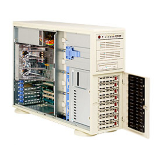
Overview The Supermicro SuperServer 7044H-T/7044H-TR is a high-end server that is com- prised of two main subsystems: the SC743T-650/SC743T-R760 tower/4U server chassis and the X6DHT-G Intel Xeon dual processor serverboard. Please refer to our web site for information on operating systems that have been certifi ed for use with the SuperServer 7044H-T/7044H-TR (www.supermicro.com). -
Page 12: Serverboard Features
ERVER 7044H-T/7044H-TR User's Manual Serverboard Features At the heart of the SuperServer 7044H-T/7044H-TR lies the X6DHT-G, a dual processor serverboard based on the Intel E7520 chipset and designed to provide maximum performance. Below are the main features of the X6DHT-G. (See Figure 1-1 for a block diagram of the E7520 chipset). -
Page 13: Server Chassis Features
The following is a general outline of the main features of the SC743T-650/SC743T- R760 server chassis. System Power: 7044H-T The SC743T-650 features a single 650W power supply. The system must be shut down and the AC power cord removed before replacing or performing any service on the power supply unit. - Page 14 Serial ATA drives. Front Control Panel The SuperServer 7044H-T/7044H-TR's control panel provides you with system monitoring and control. LEDs indicate system power, HDD activity, network activ- ity, system overheat and power supply failure. A main power button and a system reset button are also included.
-
Page 15: System Block Diagram
Figure 1-1. Intel E7520 Chipset: System Block Diagram Note: This is a general block diagram. Please see Chapter 5 for details. 1_PCIX-100 1_PCIX-100 Slot Slot SATA SATA HC2_8Ports HC2_8Ports PCIX BUS(100 MHZ) PCIX BUS(100 MHZ) 1_PCIX-100 1_PCIX-100 GRN_Slot GRN_Slot PXH#1 PXH#1 1_PCIX-133 1_PCIX-133... -
Page 16: Contacting Supermicro
UPER ERVER 7044H-T/7044H-TR User's Manual Contacting Supermicro Headquarters Address: SuperMicro Computer, Inc. 980 Rock Ave. San Jose, CA 95131 U.S.A. Tel: +1 (408) 503-8000 Fax: +1 (408) 503-8008 Email: marketing@supermicro.com (General Information) support@supermicro.com (Technical Support) Web Site: www.supermicro.com Europe Address: SuperMicro Computer B.V. -
Page 17: 2-1 Overview
The 7044H-T/7044H-TR may be employed either as a tower or mounted in a rack as a 4U rackmount chassis. If using it as a tower unit, please read the Server Precautions in the next section and then skip ahead to Section 2-5. -
Page 18: Choosing A Setup Location
UPER ERVER 7044H-T/7044H-TR User's Manual Choosing a Setup Location - Leave enough clearance in front of the system to enable you to open the front door completely (~25 inches). - Leave approximately 30 inches of clearance in the back of the system to allow for suffi... -
Page 19: Rack Mounting Considerations
Chapter 2: Server Installation Rack Mounting Considerations Ambient Operating Temperature If installed in a closed or multi-unit rack assembly, the ambient operating tempera- ture of the rack environment may be greater than the ambient temperature of the room. Therefore, consideration should be given to installing the equipment in an environment compatible with the manufacturer’s maximum rated ambient tempera- ture (Tmra). -
Page 20: Installing The System Into A Rack
UPER ERVER 7044H-T/7044H-TR User's Manual Installing the System into a Rack This section provides information on installing the system into a rack unit. Rack installation requires the use of the optional rackmount kit [CSE-PT26(B)]. If the system has already been mounted into a rack or if you are using it as a tower, you can skip ahead to Sections 2-5 and 2-6. -
Page 21: Installing The Chassis Rails
Chapter 2: Server Installation Installing the Chassis Rails You will need to remove the top cover and the feet to add rack rails to the chassis. First, remove the top and right covers (top and left covers when standing as a tower chassis) by fi... -
Page 22: Installing The Rack Rails
Figure 2-3. Installing the Rails to the Chassis Installing the Rack Rails Determine where you want to place the SuperServer 7044H-T/7044H-TR in the rack. (See Rack and Server Precautions in Section 2-3.) Position the fi xed rack rail/sliding rail guide assemblies at the desired location in the rack, keeping the sliding rail guide facing the inside of the rack. -
Page 23: Installing The Server Into The Rack
Chapter 2: Server Installation Installing the Server into the Rack You should now have rails attached to both the chassis and the rack unit. The next step is to install the server into the rack. You should have two brackets in the rack mount kit. -
Page 24: Checking The Serverboard Setup
UPER ERVER 7044H-T/7044H-TR User's Manual Checking the Serverboard Setup After setting up the the system, you will need to open the unit to make sure the serverboard is properly installed and all the connections have been made. 1. Accessing the inside of the system (see Figure 2-5) [If rack mounted, fi... -
Page 25: Checking The Drive Bay Setup
Figure 2-5. Accessing the Inside of the System (Rack Confi guration shown) Checking the Drive Bay Setup Next, you should check to make sure the peripheral drives and the Serial ATA drives and SATA backplane have been properly installed and all connections have been made. - Page 26 UPER ERVER 7044H-T/7044H-TR User's Manual 4. Check the SATA disk drives Depending upon your system's confi guration, your system may have one or more drives already installed. If you need to install SATA drives, please refer to Chapter 6. 5. Check the airfl ow Airfl...
-
Page 27: Chapter 3: System Interface
System Interface Overview The control panel on the 7044H-T/7044H-TR has several LEDs and two buttons. There is also an LED on each Serial ATA drive carrier. These LEDs keep you constantly informed of the overall status of the system and the activity and health of specifi... -
Page 28: Control Panel Leds
UPER ERVER 7044H-T/7044H-TR User's Manual Control Panel LEDs The control panel located on the front of the SC743T-650/SC743T-R760 chassis has six LEDs that provide you with critical information related to different parts of the system. This section explains what each LED indicates when illuminated and any corrective action you may need to take. -
Page 29: Power Fail
Power Fail (7044H-TR only): Indicates a power supply module has failed. This should be accompanied by an audible alarm. A backup power supply module will take the load and keep the system running but the failed module will need to be replaced. - Page 30 UPER ERVER 7044H-T/7044H-TR User's Manual Notes...
-
Page 31: Chapter 4: System Safety
Electrical Safety Precautions Basic electrical safety precautions should be followed to protect yourself from harm and the SuperServer 7044H-T/7044H-TR from damage: Be aware of the locations of the power on/off switch on the chassis as well as the room's emergency power-off switch, disconnection switch or electrical outlet. -
Page 32: General Safety Precautions
General Safety Precautions Follow these rules to ensure general safety: Keep the area around the SuperServer 7044H-T/7044H-TR clean and free of clutter. The SuperServer 7044H-T/7044H-TR weighs approximately 64/70 lbs (29.1/31.8 kg.) when fully loaded. When lifting the system, two people at either end should lift slowly with their feet spread out to distribute the weight. -
Page 33: Esd Safety Precautions
After accessing the inside of the system, close the system back up and secure it to the rack unit with the retention screws after ensuring that all connections ESD Precautions Electrostatic discharge (ESD) is generated by two objects with different electrical charges coming into contact with each other. -
Page 34: Operating Precautions
Care must be taken to assure that the chassis cover is in place when the 7044H-T/7044H-TR is operating to assure proper cooling. Out of warranty damage to the 7044H-T/7044H-TR system can occur if this practice is not strictly followed. Figure 4-1. Installing the Onboard Battery... -
Page 35: Chapter 5: Advanced Serverboard Setup
Advanced Serverboard Setup This chapter covers the steps required to install processors and heatsinks to the X6DHT-G serverboard, connect the data and power cables and install add-on cards. All serverboard jumpers and connections are described and a layout and quick reference chart are included in this chapter. Remember to close the chas- sis completely when you have fi... -
Page 36: Processor And Heatsink Installation
UPERSERVER 7044H-T/7044H-TR User’s Manual Processor and Heatsink Installation When handling the processor package, avoid placing direct pressure on the label area of the fan. Also, do not place the serverboard on a conductive surface, which can damage the BIOS battery and prevent the system from booting up. - Page 37 5. Screw in two diagonal screws until just snug (do not fully tighten), then do the same with the remaining two diagonal screws. Finish by fully tightening all four screws (see Figure 5-2). 6. If installing two processors, repeat these steps to install the second processor in the CPU #2 slot.
-
Page 38: Connecting Cables
UPERSERVER 7044H-T/7044H-TR User’s Manual Connecting Cables Now that the processors are installed, the next step is to connect the cables to the serverboard. These include the data (ribbon) cables for the peripherals and control panel and the power cables. Connecting Data Cables The ribbon cables used to transfer data from the peripheral devices have been carefully routed in preconfi... -
Page 39: Connecting The Control Panel
Connecting the Control Panel JF1 contains header pins for various front control panel connectors. See Figure 5-3 for the pin locations of the various front control panel buttons and LED indi- cators. Please note that even and odd numbered pins are on opposite sides of each header. -
Page 40: I/O Ports
Figure 5-4 below for the colors and locations of the various I/O ports. Figure 5-4. Rear Panel I/O Ports Installing Memory Note: Check the Supermicro web site for recommended memory modules. Exercise extreme care when installing or removing DIMM modules to prevent any possible damage. Also note that the memory is inter- leaved to improve performance (see step 1). - Page 41 3. Gently press down on the DIMM module until it snaps into place in the slot. Repeat for all modules (see step 1 above). Memory Support The X6DHT-G supports up to 32 GB of DDR266 or up to 16 GB of DDR333 SDRAM.
-
Page 42: Adding Pci Cards
UPERSERVER 7044H-T/7044H-TR User’s Manual Adding PCI Cards PCI slots The X6DHT-G has two PCI-Express x8 slots, one 64-bit 133 MHz PCI-X slot, two 64-bit 100 MHz PCI-X slots and one 32-bit PCI slot. The SC743T-650/SC743T- R760 chassis accommodates up to six standard size PCI cards. PCI cards are installed directly to the serverboard (riser cards are not needed). -
Page 43: Serverboard Details
Serverboard Details Figure 5-6. SUPER X6DHT-G Layout FAN6 FAN5 DIMM 1A Bank 1 USB0/1 DIMM 1B Bank 1 DIMM 2A Bank 2 COM1 DIMM 2B Bank 2 DIMM 3A Bank 3 DIMM 3B Bank 3 DIMM 4A Bank 4 DIMM 4B Bank 4 JLAN1 JLAN2... -
Page 44: X6Dht-G Quick Reference
UPERSERVER 7044H-T/7044H-TR User’s Manual X6DHT-G Quick Reference Jumper Description 3rd Power Supply Detect JBT1 CMOS Clear JPG1 VGA Enable/Disable JPL1/JPL2 JLAN1/2 Enable/Disable JPS1 Marvell SATA Enable/Disable Watchdog Connector Description ATX POWER Primary 24-pin ATX Power Connector COM1/COM2 COM1/COM2 Serial Port Connectors... -
Page 45: Connector Defi Nitions
Connector Defi nitions ATX Power Connection The power supply connector meets the SSI (Superset ATX) 24-pin specifi - cation. Make sure that the orientation of the connector is correct. See the table on the right for pin defi nitions. PWR_SEC Connection In addition to the Primary ATX power connector (above), the Secondary 12v 4-pin J15 connector (J38) must... -
Page 46: Hdd Led
UPERSERVER 7044H-T/7044H-TR User’s Manual HDD LED The HDD (IDE Hard Disk Drive) LED connection is located on pins 13 and 14 of JF1. Attach the IDE hard drive LED cable to display disk activity. Refer to the table on the right for pin defi... -
Page 47: Reset Button
Reset Button The Reset Button connection is lo- cated on pins 3 and 4 of JF1. Attach it to the hardware reset switch on the computer case. Refer to the table on the right for pin defi nitions. Power Button The Power Button connection is located on pins 1 and 2 of JF1. -
Page 48: Serial Ports
UPERSERVER 7044H-T/7044H-TR User’s Manual Serial Ports The COM1 serial port is located beside the mouse port. COM2 is a header on the serverboard (see serverboard layout for location). See the table on the right for pin defi nitions. Power Fail Header... -
Page 49: Extra Universal Serial Bus Headers
Extra Universal Serial Bus Headers Two additional USB headers (USB2/3) are located near the battery on the serverboard. These are included for connection to the ports on the front of the chassis. A USB cable (not included) is needed for the connec- tion. -
Page 50: Wake-On-Lan
UPERSERVER 7044H-T/7044H-TR User’s Manual Wake-On-LAN The Wake-On-LAN header is desig- nated WOL. See the table on the right for pin defi nitions. You must enable the LAN Wake-Up setting in BIOS to use this feature. You must also have a LAN card with a Wake-on-LAN con- nector and cable. -
Page 51: Alarm Reset
Alarm Reset (JAR) The system will notify you in the event of a power supply failure. This feature assumes that Supermicro redundant power supply units are installed in the chassis. If you only have a single power supply installed, you should not connect anything to this jumper to prevent false alarms. -
Page 52: Jlan Enable/Disable
UPERSERVER 7044H-T/7044H-TR User’s Manual JLAN Enable/Disable Change the setting of jumper JPL1 to enable or disable the onboard LAN ports (JLAN1 and JLAN2) on the serverboard. See the table on the right for jumper settings. The default setting is enabled... -
Page 53: 5-10 Onboard Indicators
JP13 to prevent false alarms. See the table on right for pin defi nitions. Note: this feature can only be used on the 7044H-TR. JP10 should be dis- abled on the 7044H-T, which has only a single power supply. 5-10 Onboard Indicators JLAN1/JLAN2 LEDs The Ethernet ports (located beside the VGA port) have two LEDs. -
Page 54: 5-11 Parallel Port, Floppy And Hard Drive Connections
UPERSERVER 7044H-T/7044H-TR User’s Manual 5-11 Parallel Port, Floppy and Hard Drive Connections Note the following when connecting the fl oppy and hard disk drive cables: • The fl oppy disk drive cable has seven twisted wires. • A red mark on a wire typically designates the location of pin 1. -
Page 55: Floppy Connector
Floppy Connector The fl oppy connector is located on J12. See the table below for pin defi nitions. Chapter 5: Advanced Serverboard Setup Floppy Drive Connector Pin Defi nitions (J12) Pin# Defi nition Pin # Defi nition Ground FDHDIN Ground Reserved FDEDIN Ground... -
Page 56: Ide Connectors
UPERSERVER 7044H-T/7044H-TR User’s Manual IDE Connectors There are no jumpers to confi g- ure the onboard IDE#1 and #2 connectors. See the table on the right for pin defi nitions. IDE Drive Connectors Pin Defi nitions (J5, J6) Pin# Defi nition Pin # Defi... -
Page 57: Chapter 6: Advanced Chassis Setup
Advanced Chassis Setup This chapter covers the steps required to install components and perform simple maintenance on the SC743T-650/SC743T-R760 chassis. Following the component installation steps in the order given will eliminate most common problems. If some steps are unnecessary, skip ahead to the step that follows. Refer to Chapter 2 for instructions on installing the system as a 4U rackmount. - Page 58 UPER ERVER 7044H-T/7044H-TR User's Manual Figure 6-1. Chassis Front View System LEDs USB Ports Main Power System Reset 5.25" Drive Bays (2) Floppy Drive 8 Serial ATA Drive Bays (behind locking bezel)
-
Page 59: Front Control Panel
Front Control Panel The front control panel must be connected to the JF1 connector on the serverboard to provide you with system status and alarm indications. A ribbon cable has bundled these wires together to simplify this connection. Connect the cable from JF1 on the serverboard (making sure the red wire plugs into pin 1) to the appropriate comnnec- tor on the front control panel PCB (printed circuit board). -
Page 60: System Fans
Installing a new system fan Replace the failed fan with an identical one (Supermicro p/n FAN-0072). Install it in (and then reassemble) the fan housing, then plug the housing back into its slot; it should click into place when fully inserted. Check that the fan is working then replace the top/left side chassis panel. - Page 61 Chapter 6: Advanced Chassis Setup Figure 6-3. Removing a Chassis Fan Figure 6-4. Removing the Air Shroud...
-
Page 62: Drive Bay Installation/Removal
UPER ERVER 7044H-T/7044H-TR User's Manual Drive Bay Installation Serial ATA Drives A total of eight SATA drives may be housed in the SC743T-650/SC743T-R760 chassis. The drive IDs are preconfi gured as 0 through 7 in order from bottom to top (or from left to right if rackmounted). A bezel covers the SATA drive area but does not need to be removed to access the drives;... - Page 63 Figure 6-5. Removing a Serial ATA Drive Carrier Figure 6-6. Mounting a Serial ATA Drive in a Carrier Important! Use extreme caution when working around the SATA backplane. Do not touch the backplane with any metal objects and make sure no ribbon cables touch the backplane or obstruct the airfl...
-
Page 64: Installing A Component In The 5.25" Drive Bay
Installing Components in the 5.25" Drive Bays 1. Drive bay confi guration The 7044H-T/7044H-TR has two 5.25" drive bays. Components such as an extra fl oppy drive, IDE hard drives or CD-ROM drives can be installed into these 5.25" drive bays. -
Page 65: Power Supply
Replace with the same model - SP650-RP (p/n PWS-0056), which can be ordered directly from Supermicro (see Contact Information in the Preface). As there is only one power supply unit in the 7044H-T, the server must be powered down before removing and/or replacing the power supply for whatever reason. -
Page 66: Removing/Replacing The Power Supply
The PWR Fail LED will illuminate and remain on until the failed unit has been replaced. Re- placement units can be ordered directly from Supermicro (see contact information in the Preface). The power supply modules have a hot-swap capability, meaning you can replace the failed module without powering down the system. -
Page 67: Chapter 7: Bios
When an option is selected in the left frame, it is highlighted in white. Often a text message will accompany it. (Note that BIOS has default text messages built in. Supermicro retains the option to include, omit, or change any of these text mes- sages.) Options printed in Bold are the default settings. -
Page 68: Running Setup
UPER ERVER 7044H-T/7044H-TR User's Manual Running Setup *Default settings are in bold text unless otherwise noted. The BIOS setup options described in this section are selected by choosing the appropriate text from the main BIOS Setup screen. All displayed text is described in this section, although the screen display is often all you need to understand how to set the options (see on next page). -
Page 69: Main Bios Setup Menu
Chapter 7: BIOS Main BIOS Setup Menu Main Setup Features System Time To set the system date and time, key in the correct information in the appropriate fi elds. Then press the <Enter> key to save the data. System Date Using the arrow keys, highlight the month, day and year fi... - Page 70 UPER ERVER 7044H-T/7044H-TR User's Manual Parallel ATA This setting allows the user to enable or disable the function of Parallel ATA. The options are Disabled, Channel 0, Channel 1 and Both. Serial ATA This setting allows the user to enable or disable the function of Serial ATA. The options are Disabled and Enabled.
- Page 71 CHS Format The following items will be displayed by the BIOS: TYPE: This item displays the type of CPU. Cylinders: This item indicates the status of Cylinders. Headers: This item indicates the number of headers. Sectors: This item displays the number of sectors. Maximum Capacity: This item displays the maximum storage capacity of the system.
-
Page 72: Advanced Setup
UPER ERVER 7044H-T/7044H-TR User's Manual System Memory This display informs you how much system memory is recognized as being present in the system. Extended Memory This display informs you how much extended memory is recognized as being present in the system. - Page 73 Chapter 7: BIOS Quick Boot Mode If enabled, this feature will speed up the POST (Power On Self Test) routine by skipping certain tests after the computer is turned on. The settings are Enabled and Disabled. If Disabled, the POST routine will run at normal speed. Quiet Boot This setting allows you to Enable or Disable the diagnostic screen during boot-up.
- Page 74 UPER ERVER 7044H-T/7044H-TR User's Manual Memory Cache Cache System BIOS Area This setting allows you to designate a reserve area in the system memory to be used as a System BIOS buffer to allow the BIOS write (cache) its data into this reserved memory area.
- Page 75 Chapter 7: BIOS data back directly from the buffer without writing data to the System Memory for fast CPU data processing and operation. The options are "Uncached", "Write Through", "Write Protect", and "Write Back". Cache Extended Memory If enabled, this feature will allow the data stored in the extended memory area to be cached (written) into a buffer, a storage area in the Static DRM (SDROM) or written into L1, L2, L3 cache inside the CPU to speed up CPU operations .
- Page 76 UPER ERVER 7044H-T/7044H-TR User's Manual PCI Confi guration Access the submenu to make changes to the following settings for PCI devices. Onboard GLAN1/ GLAN2 (Gigabit- LAN) OPROM Confi gure Enabling this option provides the capability to boot from GLAN1/GLAN2. The options are Disabled and Enabled.
- Page 77 Enable Master This setting allows you to enable the selected device as the PCI bus master. The options are Enabled and Disabled. Latency Timer This setting allows you to set the clock rate for Bus Master. A high-priority, high-throughout device may benefi t from a greater Clock rate. The options are Default, 0020h, 0040h, 0060h, 0080h, 00A0h, 00C0h, and 00E0h.
- Page 78 UPER ERVER 7044H-T/7044H-TR User's Manual ECC Error Type This setting lets you select which type of interrupt to be activated as a result of an ECC error. The options are None, NMI (Non-Maskable Interrupt), SMI (System Management Interrupt) and SCI (System Control Interrupt.) SERR Signal Condition This setting specifi...
- Page 79 Thermal Management 2 If enabled, this feature allows you to select between Thermal Manager 1 and Thermal Manager 2. The options are Disable or Enable. Processor Power Management This feature allows the user to determine the processor power management mode. The options are Disabled and C States Only. If set to Disabled, C States and GV1/GV3 are disabled.
- Page 80 UPER ERVER 7044H-T/7044H-TR User's Manual Onboard COM2 This setting allows you to assign control of serial port B. The options are Enabled (user defi ned), Disabled, Auto (BIOS controlled) and OS controlled. Mode Specify the type of device that will be connected to serial port B. The options are Normal, and IR (for an infrared device).
- Page 81 DMA Channel This item allows you to specify the DMA channel for the parallel port. The options are DMA1 and DMA3. Floppy Disk Controller This setting allows you to assign control of the fl oppy disk controller. The options are Enabled (user defi ned), Disabled, and Auto (BIOS and OS controlled). Base I/O Address Select the base I/O address for the parallel port.
- Page 82 UPER ERVER 7044H-T/7044H-TR User's Manual Console Redirection Access the submenu to make changes to the following settings. COM Port Address This item allows you to specifi es to redirect the console to Onboard COM A or Onboard COM B. This setting can also be Disabled.
- Page 83 Hardware Monitor Logic CPU Temperature Threshold This option allows the user to set a CPU temperature threshold that will activate the alarm system when the CPU temperature reaches this pre-set temperature threshold. The options are 85 Highlight this and hit <Enter> to see monitor data for the following items: CPU1 Temperature: This item displays CPU1 Temperature.
-
Page 84: Security
UPER ERVER 7044H-T/7044H-TR User's Manual Security Choose Security from the Phoenix BIOS Setup Utility main menu with the arrow keys. You should see the following display. Security setting options are displayed by highlighting the setting using the arrow keys and pressing <Enter>. All Security BIOS settings are described in this section. - Page 85 Chapter 7: BIOS Set User Password When the item "Set User Password" is highlighted, hit the <Enter> key. When prompted, type the user's password in the dialogue box to set or to change the user's password, which allows access to the system at boot-up. Fixed Disk Boot Sector This setting may offer some protection against viruses when set to Write Protect, which protects the boot sector on the hard drive from having a virus written to it.
-
Page 86: Boot
UPER ERVER 7044H-T/7044H-TR User's Manual Boot Choose Boot from the Phoenix BIOS Setup Utility main menu with the arrow keys. You should see the following display. Highlighting a setting with a + or - will expand or collapse that entry. See details on how to change the order and specs of boot devices in the Item Specifi... -
Page 87: Exit
Chapter 7: BIOS Exit Choose Exit from the Phoenix BIOS Setup Utility main menu with the arrow keys. You should see the following display. All Exit BIOS settings are described in this section. Exit Saving Changes Highlight this item and hit <Enter> to save any changes you made and to exit the BIOS Setup utility. - Page 88 UPER ERVER 7044H-T/7044H-TR User's Manual Notes 7-22...
-
Page 89: Appendix A: Bios Post Codes
Appendix A BIOS POST Codes This section lists the POST (Power On Self Test) codes for the PhoenixBIOS. POST codes are divided into two categories: recoverable and terminal. Recoverable POST Errors When a recoverable type of error occurs during POST, the BIOS will display an POST code that describes the problem. - Page 90 UPER ERVER 7044H-T/7044H-TR User'sManual POST Code Description 8254 timer initialization 8237 DMA controller initialization Reset Programmable Interrupt Controller 1-3-1-1 Test DRAM refresh 1-3-1-3 Test 8742 Keyboard Controller Set ES segment register to 4 GB Auto size DRAM Initialize POST Memory Manager...
- Page 91 POST Code Description Test RAM between 512 and 640 kB Test extended memory Test extended memory address lines Jump to UserPatch1 Confi gure advanced cache registers Initialize Multi Processor APIC Enable external and CPU caches Setup System Management Mode (SMM) area Display external L2 cache size Load custom defaults (optional) Display shadow-area message...
- Page 92 UPER ERVER 7044H-T/7044H-TR User'sManual POST Code Description Check for SMART Drive (optional) Shadow option ROMs Set up Power Management Initialize security engine (optional) Enable hardware interrupts Determine number of ATA and SCSI drives Set time of day Check key lock...
- Page 93 POST Code Description Re-map I/O and memory for PCMCIA Initialize digitizer and display message Unknown interrupt The following are for boot block in Flash ROM POST Code Description Initialize the chipset Initialize the bridge Initialize the CPU Initialize system timer Initialize system I/O Check force recovery boot Checksum BIOS ROM...
- Page 94 UPER ERVER 7044H-T/7044H-TR User'sManual Notes...
-
Page 95: Appendix B: Software Installation
After all the hardware has been installed, you must fi rst confi gure the Adaptec Embedded Serial ATA RAID Driver before you install the Windows operating system. The necessary drivers are all included on the Supermicro bootable CDs that came packaged with your motherboard. (For Adaptec's SCSI Host RAID Utility, please refer to the CDs that came with your motherboard.) - Page 96 I/O throughput and providing data acces- sibility regardless of a single disk failure. By incorporating Adaptec Embedded Serial ATA into the motherboard design, Supermicro offers the user the benefi ts of SATA RAID without the high costs associated with RAID hardware.
- Page 97 Appendix B: Software Installation To run the Adaptec RAID Confi guration Utility, you will need to enable the RAID function in the system BIOS (refer to Chapter 7 for System BIOS Confi gurations), and then press the Ctrl and A keys simultaneously when prompted to do so dur- ing the system startup.
- Page 98 UPER ERVER 7044H-T/7044H-TR User's Manual Managing Arrays Select this option to view array properties and delete arrays. The following sec- tions describe the operations Of "Managing Arrays". To select this option, use the arrow keys and the Enter key to select Managing...
- Page 99 Viewing Array Properties To view the properties of an existing array: 1. At the BIOS prompt, press Ctrl+A. 2. From the ARC menu, select Array Confi guration Utility (ACU). 3. From the ACU menu, select Manage Arrays (as shown on the previous screen.) 4.
- Page 100 UPER ERVER 7044H-T/7044H-TR User's Manual Creating Arrays Before creating arrays, make sure the disks for the array are connected and installed in your system. Note that disks with no usable space, or disks that are un-initialized are shown in gray and cannot be used. See Initializing Disk Drives.
- Page 101 Appendix B: Software Installation Assigning Array Properties Once you've create a new array, you are ready to assign properties to the ar- ray. Caution: Once the array is created and its properties are assigned, you cannot change the array properties using the ACU. You will need to use the Adaptec Storage Manager - Browser Edition.
- Page 102 UPER ERVER 7044H-T/7044H-TR User's Manual 4. The item "Create RAID via" allows you to select between the different meth- ods of creating RAID 0 and RAID 1. The following table gives examples of when each is appropriate. Raid Level Create Via...
- Page 103 Appendix B: Software Installation Notes 1. Before adding a new drive to an array, back up any data contained on the new drive. Otherwise, all data will be lost. 2. If you stop the build or clear process on a RAID 1 from ACU, you can restart it by pressing Ctrl+R.
- Page 104 UPER ERVER 7044H-T/7044H-TR User's Manual Adding a Bootable Array 1. From the Main menu, select Manage Arrays. 2. From the list of arrays, select the array you want to make bootable and press Ctrl+B. 3. Enter Y to create a bootable array when the following message is displayed: "This will make all other existing bootable array non-bootable.
- Page 105 Appendix B: Software Installation Adding/Deleting Hotspares Note: In order to rebuild a RAID (RAID 0 or RAID 1), you need to add a new HDD as a hotspare. 1. Turn on your computer and press Ctrl+A as prompted to access the ARC Utility.
- Page 106 UPER ERVER 7044H-T/7044H-TR User's Manual Initializing Disk Drives If an installed disk does not appear in the disk selection list for creating a new array or if it appears grayed out, you may have to initialize it before you can use it as part of an array.
- Page 107 Appendix B: Software Installation 5. Repeat Step 4 so that both drives to be initialized are selected (as shown on the following screen). B-13...
- Page 108 UPER ERVER 7044H-T/7044H-TR User's Manual 6. Press Enter. 7. Read the warning message as shown on the screen below. 8. Make sure that you have selected the correct disk drives to initialize. If cor- rect, type Y to continue. Rebuilding Arrays Note 1: Rebuilding applies to Fault Tolerant arrays (RAID 1) only.
-
Page 109: Using The Disk Utilities
Appendix B: Software Installation Using the Disk Utilities The Disk Utilities enable you to format or verify the media of your Serial ATA hard disks. To access the disk utilities: 1. Turn on your computer and press Ctrl+A when prompted to access the ARC utility. - Page 110 UPER ERVER 7044H-T/7044H-TR User's Manual To Exit Adaptec RAID Confi guration Utility 1. Once you have completed RAID array confi gurations, press ESC to exit. The following screen will appear. 2. Press Yes to exit the Utility. For more information regarding the Adaptec RAID Utility, please refer to Adaptec's User's Guide in the CD included in your shipping package.
- Page 111 Appendix B: Software Installation B-2 Installing Intel's 6300ESB Driver by Adaptec and Windows OS 1. Insert Supermicro's bootable CD that came with the package into the CD drive during the system reboot. The "Super Micro Driver Diskette Maker" screen will appear.
- Page 112 UPER ERVER 7044H-T/7044H-TR User's Manual B-3 Installing Other Software Programs and Drivers Installing Other Drivers After you've installed the Windows Operating System, a screen (as shown in Figure B-1) will appear. You are now ready to install additional software programs and drivers.
- Page 113 Appendix B: Software Installation Supero Doctor III The Supero Doctor III program is a web-based management tool that offers both remote and local management tools. The local management application is called SD III Client. The Supero Doctor III program included on the CDROM that came with your motherboard allows you to monitor the environment and operations of your system.
- Page 114 Figure B-3. Supero Doctor III: Remote Control Display Note: SD III Software Revision 1.0 can be downloaded from our Web site at: ftp://ftp.supermicro.com/utility/Supero_Doctor_III/. You can also download the SDIII User's Guide at: http://www.supermicro.com/PRODUCT/Manuals/SDIII/ UserGuide.pdf. For Linux, we recommend using Supero Doctor II.
-
Page 115: Appendix C: System Specifi Cations
Appendix C: System Specifi cations Appendix C System Specifi cations Processors Single or dual Intel® Xeon™ 604-pin processors to 3.60 GHz at a front side (system) bus speed of 800 MHz. Note: Please refer to our web site for a complete listing of supported processors. Chipset Intel E7520 chipset BIOS... - Page 116 Rated Output Power: 760W (Model# SP762-TS, Part# PWS-0050/PWS- 0050M)* Rated Output Voltages: +3.3V (36A), +5V (36A), +12V (50A), +5Vsb (3.5A), -12V (1A) BTU Rating 7044H-T: 3431 BTUs/hr (for rated output power of 650W) 7044H-TR: 3725 BTUs/hr (for rated output power of 760W)
- Page 117 Appendix C: System Specifi cations Operating Environment Operating Temperature: 10º to 35º C (50º to 95º F) Non-operating Temperature: -40º to 70º C (-40º to 158º F) Operating Relative Humidity: 8% to 90% (non-condensing) Non-operating Relative Humidity: 5 to 95% (non-condensing) Regulatory Compliance Electromagnetic Emissions: FCC Class B, EN 55022 Class B, EN 61000-3-2/-3-3, CISPR 22 Class B...
- Page 118 UPER ERVER 7044H-T/7044H-TR User's Manual Notes...
Need help?
Do you have a question about the 7044H-T and is the answer not in the manual?
Questions and answers