Table of Contents
Advertisement
Quick Links
Advertisement
Table of Contents

Related Manuals for Supermicro SuperServer 7049P-TRT


Summary of Contents for Supermicro SuperServer 7049P-TRT
- Page 1 SuperServer ® 7049P-TR 7049P-TRT USER’S MANUAL Revision 1.0a...
- Page 2 State of California, USA. The State of California, County of Santa Clara shall be the exclusive venue for the resolution of any such disputes. Supermicro's total liability for all claims will not exceed the price paid for the hardware product.
- Page 3 If you have any questions, please contact our support team at: support@supermicro.com This manual may be periodically updated without notice. Please check the Supermicro website for possible updates to the manual revision level. Warnings Special attention should be given to the following symbols used in this manual.
-
Page 4: Table Of Contents
SuperServer 7049P-TR(T) User's Manual Contents Chapter 1 Introduction 1.1 Overview ..........................8 1.2 Unpacking the System ......................8 1.3 System Specifications ......................9 1.4 Server Chassis Features ....................10 Control Panel ........................10 Front Features ........................11 Rear Features ........................12 1.5 Motherboard Layout ......................13 Chapter 2 Rack Mount Installation 2.1 Overview ..........................17 2.2 Preparing for Rack Mounting .....................17 Choosing a Setup Location ....................17... - Page 5 Preface Chapter 3 Maintenance and Component Installation 3.1 Removing Power ........................28 3.2 Accessing the System ......................29 3.3 Motherboard Components ....................30 Processor and Heatsink Installation ..................30 The Xeon Scalable Processor ..................30 Overview of the Processor Socket Assembly ..............31 Heatsinks ........................32 Overview of the Processor Heatsink Module (PHM) .............33 Assembling the Processor Package ................34 Assembling the Processor Heatsink Module (PHM) .............36 Preparing the CPU Socket for Installation..............37...
- Page 6 SuperServer 7049P-TR(T) User's Manual Chapter 4 Motherboard Connections 4.1 Power Connections ......................59 4.2 Headers and Connectors ....................60 Control Panel ........................64 Data Cables ........................66 4.3 Input/Output Ports and Interface Buttons ................67 4.4 Jumpers ..........................68 Explanation of Jumpers ....................68 4.5 LED Indicators ........................70 Chapter 5 Software 5.1 OS Installation ........................72 Installing the Windows OS for a RAID System ..............72...
- Page 7 Super Micro Computer, Inc. 980 Rock Ave. San Jose, CA 95131 U.S.A. Tel: +1 (408) 503-8000 Fax: +1 (408) 503-8008 Email: marketing@supermicro.com (General Information) support@supermicro.com (Technical Support) Website: www.supermicro.com Europe Address: Super Micro Computer B.V. Het Sterrenbeeld 28, 5215 ML...
-
Page 8: Overview
SuperServer 7049P-TR(T) User's Manual Chapter 1 Introduction 1.1 Overview This chapter provides a brief outline of the functions and features of the 7049P-TR(T). The 7049P-TR(T) is based on the X11DPi-N(T) motherboard and the SC745BAC-R1K28B chassis. The server offers two network ports: •... -
Page 9: System Specifications
Chapter 1: Introduction 1.3 System Specifications The following table provides an overview of the main features of the 7049P-TR(T) server. Refer to Appendix C for additional specifications. System Specifications Motherboard X11DPi-N (7049P-TR), X11DPi-NT (7049P-TRT) Chassis SC745BAC-R1K28B Supports dual Intel 81xx/61xx/51xx/41xx/31xx series (Socket P0) processors which offer Intel UltraPath Interconnect (UPI) of up to 10.4 GT/s Memory Supports up to 2 TB of 3DS LRDIMM/LRDIMM/3DS RDIMM/RDIMM/NV-DIMM DDR4 (288-pin) ECC... -
Page 10: Server Chassis Features
SuperServer 7049P-TR(T) User's Manual 1.4 Server Chassis Features Control Panel The switches and LEDs located on the control panel are described below. See Chapter 4 for details on the control panel connections. Figure 1-1. Control Panel View Control Panel Features Item Feature Description... -
Page 11: Front Features
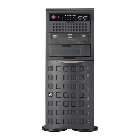
Chapter 1: Introduction Front Features The SC745BAC-R1K28B is a tower chassis. See the illustration below for the features included on the front of the chassis. Figure 1-2. Chassis Front View Front Chassis Features Item Feature Description Control Panel Front control panel with LEDs and buttons (see preceding page) Peripheral Drive Bays Three 5.25"... -
Page 12: Rear Features
SuperServer 7049P-TR(T) User's Manual Rear Features The illustration below shows the features included on the rear of the chassis. Figure 1-3. Chassis Rear View Rear Chassis Features Item Feature Description Power Supply Redundant 1280 W Platinum Level Power Supplies I/O Back Panel Rear I/O ports (see Section 4.3) Fans Two 8-cm exhaust fans... -
Page 13: Motherboard Layout
Chapter 1: Introduction 1.5 Motherboard Layout Below is a layout of the X11DPi-N(T) with jumper, connector and LED locations shown. See the table on the following pages for descriptions. For detailed descriptions, pinout information and jumper settings, refer to Chapter 4. IPMI LAN LEDM1 SLOT6... - Page 14 Gigabit LAN/10G LAN Ethernet Ports on the IO back panel (10G LAN ports on LAN1/LAN2 X11DPi-NTX11DPi-N(T) only) S-SATA0-3 S-SATA 3.0 iPass header supported by the Intel SCU S-SATA Ports with built-in power pins and with support of Supermicro SuperDOM (Disk On Module) S-SATA4/S-SATA5 devices SLOT1/SLOT3 PCI-Express 3.0 X8 Slots supported by CPU1 SLOT2 PCI-Express 3.0 X16 Slot supported by CPU1...
- Page 15 Chapter 1: Introduction Connector Description USB0/1 Back panel USB 2.0 Ports USB2/3 Front Accessible USB 2.0 Header USB4/5 Back panel USB 3.0 Ports USB6 Type A USB 3.0 Header USB7/8 Front Accessible USB 3.0 Header VGA Port Description State: Status UID (Unit Identifier) LED Solid Blue: Unit identified Onboard Power LED...
- Page 16 SuperServer 7049P-TR(T) User's Manual VCCP0 VCCP1 DDR4 DDR4 SLOT 2 PCI-E X16 G3 (LANE REVERSE) PCI-E X8 G3 PCI-E X16 G3 SLOT 1 PCI-E X8 G3 PCI-E X16 G3 SLOT 4 PCI-E X16 G3 2 x NVME PCI-E X8 G3 SLOT 3 (LANE REVERSE) DMI3...
-
Page 17: Chapter 2 Rack Mount Installation
Chapter 2: Rack Mount Installation Chapter 2 Rack Mount Installation 2.1 Overview This chapter provides instructions for preparing and mounting your chassis in a rack. By default, the chassis is shipped configured as a tower. The tower top cover and bottom feet must be removed to mount in a rack. -
Page 18: Server Precautions
SuperServer 7049P-TR(T) User's Manual • You should extend only one server or component at a time; extending two or more simul- taneously may cause the rack to become unstable. • When initially installing the server to a rack, test that the rail locking tabs engage to prevent the server from being overextended. -
Page 19: Circuit Overloading
Chapter 2: Rack Mount Installation Circuit Overloading Consideration should be given to the connection of the equipment to the power supply circuitry and the effect that any possible overloading of circuits might have on overcurrent protection and power supply wiring. Appropriate consideration of equipment nameplate ratings should be used when addressing this concern. -
Page 20: Chassis Preparation
SuperServer 7049P-TR(T) User's Manual 2.3 Chassis Preparation The chassis is shipped with the tower top cover and feet installed. Both must be removed for before installing the rails. Removing the Tower Top Cover 1. Locate the chassis cover lock (blue lever) at the rear of the chassis cover. 2. -
Page 21: Installing The Rails
Chapter 2: Rack Mount Installation 2.4 Installing the Rails There are a variety of rack units on the market, which may require a slightly different assembly procedure. Do not use a two post "telco" type rack. This rail set fits a rack between 26" and 35.9"... -
Page 22: Installing The Inner Rails
SuperServer 7049P-TR(T) User's Manual Installing the Inner Rails Identify the left and right inner rails. 1. Attach the handles to the front sides of the chassis with three screws each. 2. Position the inner rails along the side of the chassis making sure the screw holes line 3. -
Page 23: Assembling And Installing The Outer Rails
Chapter 2: Rack Mount Installation Assembling and Installing the Outer Rails Each outer rail comes in three sections that require assembly before mounting onto the rack. 1. Find the outer rail mounting brackets in the chassis accessory box. • A pair of long brackets for the rear of each rail •... -
Page 24: Installing The Server Into The Rack
SuperServer 7049P-TR(T) User's Manual 2.5 Installing the Server into the Rack After attaching rails to both the chassis and the rack, slide the server into the rack. 1. Pull the middle rail out of the front of the outer rail and make sure that the ball bearing shuttle is locked at the front of the middle rail. -
Page 25: Removing The Chassis From The Rack
Chapter 2: Rack Mount Installation Removing the Chassis from the Rack Caution! It is dangerous for a single person to off-load the heavy chassis from the rack without assistance. Be sure to have sufficient assistance supporting the chassis when removing it from the rack. -
Page 26: Control Panel Orientation
SuperServer 7049P-TR(T) User's Manual 2.6 Control Panel Orientation The server can be configured for either tower or server rack orientation. It is shipped in tower mode and can be immediately used as desktop server. To use it in a rack, rotate the module that contains the control panel and the three drive trays ( in Figure 2-6) 90 degrees. - Page 27 Chapter 2: Rack Mount Installation Rotating the Control Panel/Drive Module for Rack Mounting 1. Power down the system as described in section 3.1 and open the chassis cover. 2. Disconnect any cables from the back of the Control Panel/Drive Module. 3.
-
Page 28: Chapter 3 Maintenance And Component Installation
SuperServer 7049P-TR(T) User's Manual Chapter 3 Maintenance and Component Installation This chapter provides instructions on installing and replacing main system components. To prevent compatibility issues, only use components that match the specifications and/or part numbers given. Installation or replacement of most components require that power first be removed from the system. -
Page 29: Accessing The System
Chapter 3: Maintenance and Component Installation 3.2 Accessing the System The chassis offers a removable side cover (top, if rack mounted) which allows access to the internal components. Removing the Side Cover 1. Locate the latch on the cover, depress where it says "push," then lift the latch to release the cover. -
Page 30: Motherboard Components
When receiving a motherboard without a processor pre-installed, make sure that the plastic CPU socket cap is in place and none of the socket pins are bent; otherwise, contact your retailer immediately. • Refer to the Supermicro website for updates on CPU support. The Xeon Scalable Processor SKX Processor SKX-F Processor Figure 3-2. -
Page 31: Overview Of The Processor Socket Assembly
Chapter 3: Maintenance and Component Installation Overview of the Processor Socket Assembly The processor socket assembly contains 1) the Intel SKX(-F) CPU, 2) the narrow processor clip, 3) the dust cover, and 4) the CPU socket. 1. SKX (-F) CPU (for the non-F model) 2. -
Page 32: Heatsinks
SuperServer 7049P-TR(T) User's Manual Heatsinks The 7049P-TR(T) server uses this heatsink design for each processor. Figure 3-3. Heatsink SNK-P0068PS... -
Page 33: Overview Of The Processor Heatsink Module (Phm)
Chapter 3: Maintenance and Component Installation Overview of the Processor Heatsink Module (PHM) The Processor Heatsink Module (PHM) contains 1) a heatsink, 2) a narrow processor clip, and 3) the SKX(-F) processor. 1. Heatsink 2. Narrow processor clip 3. SKX(-F) Processor (Bottom View for a non-F Model) (Bottom View for an F Model;... -
Page 34: Assembling The Processor Package
SuperServer 7049P-TR(T) User's Manual Assembling the Processor Package Attach the processor to the narrow processor clip to create the processor package. Caution: Be careful handling the CPU. Do not touch the underside. Wear ESD gloves. 1. On the top corner of the CPU, locate pin 1 (A), marked by a triangle. Also, locate notch B and notch C (and notch D for -F models) on the CPU as shown below. - Page 35 Chapter 3: Maintenance and Component Installation CPU (Upside Down) Align Notch D of the CPU w/CPU LGA Lands up and Notch D of the Processor Clip Align Notch C of the CPU Pin 1 and Notch C of the Processor Clip Align Notch B of the CPU and Notch B of the Processor Clip CPU/Heatsink Package...
-
Page 36: Assembling The Processor Heatsink Module (Phm)
SuperServer 7049P-TR(T) User's Manual Assembling the Processor Heatsink Module (PHM) After creating the processor package assembly, mount it onto the heatsink to create the processor heatsink module (PHM). 1. Locate "1" on the heatsink label and the corner next to it. With your index finger pressing against the screw at this corner, turn the heatsink upside down with the thermal grease side facing up. -
Page 37: Preparing The Cpu Socket For Installation
Chapter 3: Maintenance and Component Installation Preparing the CPU Socket for Installation This motherboard comes with the CPU socket assembled in the factory. It includes a dust cover, a socket bracket, the CPU socket (P0), and a back plate. CPU Socket with Dust Cover On Removing the Dust Cover from the CPU Socket Remove the dust cover from the CPU socket, exposing the socket pins as shown below. -
Page 38: Installing The Processor Heatsink Module (Phm)
SuperServer 7049P-TR(T) User's Manual Installing the Processor Heatsink Module (PHM) 1. Locate the triangle (pin 1) on the CPU socket, and locate the triangle (pin 1) at the corner of the PHM that is closest to "1." (If you have difficulty locating pin 1, turn the PHM upside down. -
Page 39: Connecting An Hfi Carrier Card
Chapter 3: Maintenance and Component Installation Connecting an HFI Carrier Card A host fabric interface (HFI) carrier card can be connected the JHFI sideband header and to an SKX-F processor. Two HFI headers are located on the X11DPi-N(T) motherboard. JHFI1 is used for CPU 1, and JHFI2 is for CPU2. -
Page 40: Removing The Processor Heatsink Module From The Motherboard
SuperServer 7049P-TR(T) User's Manual Removing the Processor Heatsink Module from the Motherboard Before removing the processor heatsink module (PHM), power down as described in Section 3.1. 1. Using a T30 Torx-bit screwdriver, loosen and remove the screws on the PHM from the socket, starting with the screw marked #4, in the sequence of 4, 3, 2, 1. -
Page 41: Memory
DIMMs in one channel while populating one DIMM in another channel on the same motherboard will result in reduced memory performance. Check the Supermicro website for possible updates to memory support. DIMM Module Population Configuration For optimal memory performance, follow the specifications below when populating memory. - Page 42 SuperServer 7049P-TR(T) User's Manual Key Parameters for DIMM Configurations Parameters Possible Values Number of Channels 1, 2, 3, 4, 5, or 6 Number of DIMMs per Channel 1DPC (1 DIMM Per Channel) or 2DPC (2 DIMMs Per Channel) DIMM Type RDIMM (w/ECC), LRDIMM, 3DS-LRDIMM DIMM Construction - non-3DS RDIMM Raw Cards: A/B (2RX4), C (1RX4), D (1RX8), E (2RX8) - 3DS RDIMM Raw Cards: A/B (4RX4)
-
Page 43: Install Procedure
Chapter 3: Maintenance and Component Installation Install Procedure The DIMM slots must be populated in the following order: P1-DIMMA1, P1-DIMMD1, P1- DIMMB1, P1-DIMME1, and P1-DIMMC1, P1-DIMMF1. The blue slots must be populated first. Caution: Exercise caution when installing or removing memory modules to prevent damage to the DIMMs or slots. -
Page 44: Pcie M.2 Slot
SuperServer 7049P-TR(T) User's Manual PCIe M.2 Slot The motherboard has one M.2 slot. M.2 was formerly Next Generation Form Factor (NGFF) and serves to replace mini-PCIe. M.2 allows for a variety of card sizes, increased functionality, and spatial efficiency. The M.2 socket on the motherboard supports PCIe 3.0 X4 (32 Gb/s) SSD cards in the 2280 and 22110 form factors. -
Page 45: Motherboard Battery
Chapter 3: Maintenance and Component Installation Motherboard Battery The motherboard uses non-volatile memory to retain system information when system power is removed. This memory is powered by a lithium battery residing on the motherboard. Replacing the Battery Begin by removing power from the system as described in section 3.1. 1. -
Page 46: Chassis Components
2.5" drives with a bracket. Or two 5.25" bays can be replaced by an optional enclosure called a mobile rack that houses eight hot-swap 2.5" drives. Additional cables are also required. Note: Enterprise level hard disk drives are recommended for use in Supermicro chassis and servers. For information on recommended HDDs, visit the Supermicro website at http://www. -
Page 47: Installing The Standard 3.5" Drives
Chapter 3: Maintenance and Component Installation Installing the Standard 3.5" Drives Removing Drive Carriers from the Chassis 1. Swing open the front bezel. 2. Press the release button on the drive carrier. This extends the drive carrier handle. Figure 3-7. Removing a Drive Carrier 3. - Page 48 SuperServer 7049P-TR(T) User's Manual Installing a Hard Drive 1. Place the hard drive carrier on a flat surface. 2. Insert the hard drive into the carrier with the printed circuit board side facing downward and so that the mounting holes in the drive align with those in the drive carrier. 3.
-
Page 49: Configuring The 5.25" Drive Bays
Chapter 3: Maintenance and Component Installation Configuring the 5.25" Drive Bays The control panel/drive module includes three 5.25" drive bays under the front control panel. It can be set up in a variety of configurations to suit the user's needs. • Up to three 5.25" peripheral drives, such as a DVD drive •... - Page 50 SuperServer 7049P-TR(T) User's Manual Installing a Storage Drive into a 5.25" Tray One 3.5" drive, or two 2.5" drives with an optional bracket (pn MCP-220-00044-0N) can be installed. An optional expansion card and cables are also required. 1. Remove the tray from the drive bay. 2.
- Page 51 Chapter 3: Maintenance and Component Installation Installing a 5.25" Peripheral Device An optional peripheral device such as a DVD drive can be installed in a 5.25" bay. 1. Remove the tray from the drive bay. 2. Re-use the side rails from the tray and install them onto the peripheral device. Drive Tray Side Rails Figure 3-13.
-
Page 52: Additional Storage Drives In A Mobile Rack
SuperServer 7049P-TR(T) User's Manual Additional Storage Drives in a Mobile Rack The chassis accepts a Supermicro mobile rack (pn CSE-M28SABP) in place of two 5.25" bays. This adds eight hot-swap 2.5" SAS or SATA drives. An optional expansion card and cables are also required. - Page 53 Chapter 3: Maintenance and Component Installation Rail Figure 3-15. Mobile Rack with Drive Tray Rails 3. Install a drive tray rail onto each side of the mobile rack. Make sure the arrow on the rail points toward the front of the chassis. 4.
-
Page 54: Installing Expansion Cards
SuperServer 7049P-TR(T) User's Manual Installing Expansion Cards The system can accommodate six PCIe cards. The chassis has seven slots, but the slot nearest the chassis top is not supported by this motherboard. Expansion Card Chassis Slots Figure 3-16. PCI Slots Installing an Expansion Card 1. -
Page 55: System Cooling
Chapter 3: Maintenance and Component Installation System Cooling Three 8-cm fans located in the center of the chassis provide cooling airflow while two 8-cm exhaust fans at the rear of the chassis expel hot air. The chassis is also fitted with an air shroud to concentrate the flow of cooling air over the areas of highest generated heat. -
Page 56: Air Shroud
SuperServer 7049P-TR(T) User's Manual Air Shroud Air shrouds concentrate airflow to maximize fan efficiency. It covers the processors and heatsinks. Installing the Air Shroud The air shroud fits behind the two fans closest to the power supply. Align the pins and press the air shroud into the chassis. -
Page 57: Power Supply
The hot-swap capability of the power supply modules allows you to replace the failed module without powering down the system. Replacement units can be ordered directly from Supermicro (see contact information in the Preface). -
Page 58: Removing The Front Bezel
SuperServer 7049P-TR(T) User's Manual Replacing the Power Supply You do not need to shut down the system to replace a power supply module. 1. Unplug the AC power cord from the failed power supply module. 2. Push the release tab on the power module to the side to unlock it then grasp the handle to pull it from the chassis. -
Page 59: Chapter 4 Motherboard Connections
Chapter 4: Motherboard Connections Chapter 4 Motherboard Connections This section describes the connections on the motherboard and provides pinout definitions. Note that depending on how the system is configured, not all connections are required. The LEDs on the motherboard are also described here. A motherboard layout indicating component locations may be found in Chapter 1. -
Page 60: Headers And Connectors
SATA is supported on the X11DPi-N(T) motherboard by three iPass connectors and two SATA powered ports. The powered ports, S-SATA4/S-SATA5, are yellow connectors with power pins built in. They can be used with Supermicro SuperDOMs and do not require external power cables. - Page 61 Chapter 4: Motherboard Connections TPM Header The JTPM1 header is used to connect a Trusted Platform Module (TPM)/Port 80, which is available from a third-party vendor. A TPM/Port 80 connector is a security device that supports encryption and authentication in hard drives. It allows the motherboard to deny access if the TPM associated with the hard drive is not installed in the system.
- Page 62 SuperServer 7049P-TR(T) User's Manual Power SMBus (I C) Header The Power System Management Bus (I C) connector (JPI C1) monitors the power supply, fan, and system temperatures. Power SMB Header Pin Definitions Pin# Definition Clock Data PMBUS_Alert Ground +3.3V 4-pin BMC External I C Header A System Management Bus header for IPMI 2.0 is located at JIPMB1.
- Page 63 C) headers (JNVI2C1/2) are used for PCIe SMBus clock and data connections and provide hot-plug support by a dedicated SMBus interface. This feature is only available for a Supermicro complete system with a proprietary NVMe add-on card and cable installed. NVMe SMBus Header...
-
Page 64: Control Panel
SuperServer 7049P-TR(T) User's Manual Control Panel JF1 contains header pins for various control panel connections. See the figure below for the pin locations and definitions of the control panel buttons and LED indicators. All JF1 wires have been bundled into a single cable to simplify this connection. Make sure the red wire plugs into pin 1 as marked on the motherboard. - Page 65 Chapter 4: Motherboard Connections Power Fail LED The Power Fail LED connection is located on pins 5 and 6 of JF1. Power Fail LED Pin Definitions (JF1) Pin# Definition 3.3V PWR Supply Fail Overheat (OH)/Fan Fail Connect an LED cable to pins 7 and 8 of JF1 to use the Overheat/Fan Fail LED connections. The LED on pin 8 provides warnings of overheat or fan failure.
-
Page 66: Data Cables
SuperServer 7049P-TR(T) User's Manual HDD LED/UID Switch The HDD LED/UID Switch connection is located on pins 13 and 14 of JF1. Attach a cable to Pin 14 to show hard drive activity status. Attach a cable to Pin 13 to use UID switch. Refer to the table below for pin definitions. -
Page 67: Input/Output Ports And Interface Buttons
Chapter 4: Motherboard Connections 4.3 Input/Output Ports and Interface Buttons The rear I/O panel offers these ports and control switches. Figure 4-2. Back Panel I/O Ports Back Panel I/O Ports Description No. Description COM1 USB 1 USB 4 GLAN1 (7049P-TR), 10G_LAN1 7049P-TRT) USB 5 GLAN2 (7049P-TR), 10G_LAN2 (7049P-TRT) IPMI LAN... -
Page 68: Jumpers
SuperServer 7049P-TR(T) User's Manual 4.4 Jumpers Explanation of Jumpers To modify the operation of the motherboard, jumpers are used to choose between optional settings. Jumpers create shorts between two pins to change the function associated with it. Pin 1 is identified with a square solder pad on the printed circuit board. See the motherboard layout page for jumper locations. - Page 69 Chapter 4: Motherboard Connections Management Engine (ME) Recovery Use jumper JPME1 to select ME Firmware Recovery mode, which will limit resource allocation for essential system operation only in order to maintain normal power operation and management. In the single operation mode, online upgrade will be available via Recovery mode.
-
Page 70: Led Indicators
SuperServer 7049P-TR(T) User's Manual I2C Bus for VRM Jumpers JVRM1 and JVRM2 allow the BMC or the PCH to access CPU and memory VRM controllers. Jumper Settings Jumper Setting Definition BMC (Normal) 4.5 LED Indicators LAN LEDs The LAN ports are located on the I/O back panel on the motherboard. Each Ethernet LAN port has two LEDs. - Page 71 Chapter 4: Motherboard Connections BMC Heartbeat LED LEDM1 is the BMC heartbeat indicator. When the LED is blinking green, BMC is functioning normally. BMC Heartbeat LED Indicator LED Color Definition Green: BMC Normal Blinking Onboard Power LED The Onboard Power LED is located at LE2 on the motherboard. When this LED is on, the system is on.
-
Page 72: Chapter 5 Software
You must first configure RAID settings (if using RAID) before you install the Windows OS and the software drivers. To configure RAID settings, please refer to the RAID Configuration User Guides posted on our website at www.supermicro.com/support/manuals. Installing the Windows OS for a RAID System 1. -
Page 73: Driver Installation
Chapter 5: Software 5.2 Driver Installation The Supermicro FTP site contains drivers and utilities for your system at ftp://ftp.supermicro. com. Some of these must be installed, such as the chipset driver. After accessing the FTP site, go into the CDR_Images directory and locate the ISO file for your motherboard. -
Page 74: Superdoctor ® 5
5.3 SuperDoctor ® The Supermicro SuperDoctor 5 is a program that functions in a command-line or web-based interface for Windows and Linux operating systems. The program monitors such system health information as CPU temperature, system voltages, system power consumption, fan speed, and provides alerts via email or Simple Network Management Protocol (SNMP). -
Page 75: Ipmi
The X11DPi-N(T) support the Inteliigent Platform Management Interface (IPMI). IPMI is used to provide remote access, monitoring and management. There are several BIOS settings that are related to IPMI. For general documentation and information on IPMI, please visit our website at: http://www.supermicro.com/products/nfo/IPMI.cfm. -
Page 76: Chapter 6 Bios
SuperStorage Server 7049P-TR(T) User's Manual Chapter 6 BIOS 6.1 Introduction This chapter describes the AMI BIOS setup utility for the X11DPi-N(T) and provides the instructions on navigating the setup screens. The BIOS is stored in a Flash EEPROM and can be updated. Note: Due to periodic changes to the BIOS, some settings may have been added or deleted since this manual was published. - Page 77 HH:MM:SS format. Note: The time is in the 24-hour format. For example, 5:30 P.M. appears as 17:30:00. The date's default value is 01/01/2016 after RTC reset. Supermicro X11DPi-N/X11DPi-NT (Motherboard model) BIOS Version Build Date (of the BIOS)
-
Page 78: Advanced Setup Configurations
SuperStorage Server 7049P-TR(T) User's Manual 6.3 A dvanced Setup Configurations Use the arrow keys to select the Advanced tab and press <Enter> to access the submenu items. Caution: Take caution when changing the Advanced settings. An incorrect value, a very high DRAM frequency, or an incorrect DRAM timing setting may make the system unstable. If this occurs, revert to the manufacture default settings. - Page 79 Chapter 6: BIOS Option ROM Messages Use this feature to set the display mode for the Option ROM. Select Keep Current to use the current AddOn ROM display setting. Select Force BIOS to use the Option ROM display mode set by the system BIOS. The options are Force BIOS and Keep Current. Bootup NumLock State Use this feature to set the Power-on state for the Numlock key.
- Page 80 SuperStorage Server 7049P-TR(T) User's Manual CPU Configuration Warning: Setting the wrong values in the following sections may cause the system to malfunc- tion. Processor Configuration The following CPU information will be displayed: • Processor BSP Revision • Processor Socket • Processor ID •...
- Page 81 Chapter 6: BIOS PPIN Control Select Unlock/Enable to use the Protected-Processor Inventory Number (PPIN) in the system. The options are Unlock/Enable and Unlock/Disable. Hardware Prefetcher (Available when supported by the CPU) If this feature is set to Enable, the hardware prefetcher will prefetch streams of data and instructions from the main memory to the Level 2 (L2) cache to improve CPU performance.
- Page 82 SuperStorage Server 7049P-TR(T) User's Manual Advanced Power Management Configuration CPU P State Control SpeedStep (PStates) EIST (Enhanced Intel SpeedStep Technology) allows the system to automatically adjust processor voltage and core frequency in an effort to reduce power consumption and heat dissipation. Please refer to Intel’s website for detailed information. The options are Disable and Enable.
- Page 83 Chapter 6: BIOS Enhanced Halt State (C1E) Select Enable to enable "Enhanced Halt State" support, which will significantly reduce the CPU's power consumption by minimizing CPU's clock cycles and reduce voltage during a "Halt State." The options are Disable and Enable. Package C State Control ...
- Page 84 SuperStorage Server 7049P-TR(T) User's Manual Link L0p Enable Select Enable to enable Link L0p. The options are Disable, Enable, and Auto. Link L1 Enable Select Enable to enable Link L1 (Level 1 link). The options are Disable, Enable, and Auto. IO Directory Cache Select Enable for the IODC (I/O Directory Cache) to generate snoops instead of generating memory lockups for remote IIO (InvIToM) and/or WCiLF (Cores).
- Page 85 Chapter 6: BIOS Memory Topology This item displays the information of onboard memory modules as detected by the BIOS. • P1 DIMMA1 • P1 DIMMB1 • P2 DIMMA1 • P2 DIMMB1 Memory RAS (Reliability_Availability_Serviceability) Configuration Use this submenu to configure the following Memory RAS settings. Static Virtual Lockstep Mode Select Enable to support Static Virtual Lockstep mode to enhance memory performance.
- Page 86 SuperStorage Server 7049P-TR(T) User's Manual roughly 64 GB of memory behind the IO hub will be scrubbed every day. The options are Enable and Disable. Patrol Scrub Interval Use this item to specify the number of hours (between 0 to 24) required for the system to complete a full patrol scrubbing.
- Page 87 Chapter 6: BIOS • PCI-E Port Link Max • PCI-E Port Link Speed PCI-E Port Max (Maximum) Payload Size (Available for CPU 1 Configuration only) Select Auto for the system BIOS to automatically set the maximum payload value for a PCI-E device specified by to user to enhance system performance. The options are Auto, 128B, and 256B.
- Page 88 SuperStorage Server 7049P-TR(T) User's Manual PassThrough DMA Select Enable for the Non-Iscoh VT-d engine to pass through DMA (Direct Memory Access) to enhance system performance. The options are Enable and Disable. Select Enable to enable ATS (Address Translation Services) support for the Non-Iscoh VT-d engine to enhance system performance.
- Page 89 Chapter 6: BIOS South Bridge The following South Bridge information will display: • USB Module Version • USB Devices Legacy USB Support Select Enabled to support onboard legacy USB devices. Select Auto to disable legacy support if there are no legacy USB devices present. Select Disable to have all USB devices available for EFI applications only.
- Page 90 SuperStorage Server 7049P-TR(T) User's Manual SATA Configuration When this submenu is selected, the AMI BIOS automatically detects the presence of the SATA devices that are supported by the Intel PCH chip and displays the following items: SATA Controller This item enables or disables the onboard SATA controller supported by the Intel PCH chip. The options are Enable and Disable.
- Page 91 Chapter 6: BIOS SATA Device Type Use this item to specify if the device installed on the SATA port selected by the user should be connected to a Solid State drive or a Hard Disk Drive. The options are Hard Disk Drive and Solid State Drive.
- Page 92 SuperStorage Server 7049P-TR(T) User's Manual Spin Up Device On an edge detect from 0 to 1, set this item to allow the sSATA device installed on the sSATA port specified by the user to start a COMRESET initialization. The options are Enable and Disable.
- Page 93 Chapter 6: BIOS MMCFG Base This feature determines the lowest MMCFG (Memory-Mapped Configuration) base assigned to PCI devices. The options are 1G, 1.5G, 1.75G. 2G, 2.25G, and 3G. VGA Priority Use this item to select the graphics device to be used as the primary video display for system boot.
- Page 94 SuperStorage Server 7049P-TR(T) User's Manual Ipv4 PXE Support Select Enabled to enable Ipv4 PXE boot support. If this feature is disabled, it will not create the Ipv4 PXE boot option. The options are Disabled and Enabled. Ipv4 HTTP Support Select Enabled to enable Ipv4 HTTP boot support. If this feature is disabled, it will not create the Ipv4 HTTP boot option.
- Page 95 Chapter 6: BIOS The options for Serial Port 1 are Auto, (IO=3F8h; IRQ=4), (IO=3F8h; IRQ=3, 4, 5, 6, 7, 9, 10, 11, 12), (IO=2F8h; IRQ=3, 4, 5, 6, 7, 9, 10, 11, 12); (IO=3E8h; IRQ=3, 4, 5, 6, 7, 9, 10, 11, 12), and (IO=2E8h;...
- Page 96 SuperStorage Server 7049P-TR(T) User's Manual Bits Per second Use this feature to set the transmission speed for a serial port used in Console Redirection. Make sure that the same speed is used in the host computer and the client computer. A lower transmission speed may be required for long and busy lines.
- Page 97 Chapter 6: BIOS Putty KeyPad This feature selects Function Keys and KeyPad settings for Putty, which is a terminal emulator designed for the Windows OS. The options are VT100, LINUX, XTERMR6, SCO, ESCN, and VT400. Redirection After BIOS Post Use this feature to enable or disable legacy Console Redirection after BIOS POST. When the option-Bootloader is selected, legacy Console Redirection is disabled before booting the OS.
- Page 98 SuperStorage Server 7049P-TR(T) User's Manual Odd if the parity bit is set to 0, and the number of 1's in data bits is odd. Select None if you do not want to send a parity bit with your data bits in transmission. Select Mark to add a mark as a parity bit to be sent along with the data bits.
- Page 99 Chapter 6: BIOS Legacy Console Redirection Settings Legacy Console Redirection Settings Use the feature to select the COM port to display redirection of Legacy OS and Legacy OPROM messages. The default setting is COM1. Serial Port for Out-of-Band Management/Windows Emergency Management Services (EMS) The submenu allows the user to configure Console Redirection settings to support Out-of- Band Serial Port management.
- Page 100 SuperStorage Server 7049P-TR(T) User's Manual ACPI Settings Use this feature to configure Advanced Configuration and Power Interface (ACPI) power management settings for your system. NUMA Support (Available when the OS supports this feature) Select Enabled to enable Non-Uniform Memory Access support to enhance system perfor- mance.
- Page 101 Chapter 6: BIOS • Active PCR Banks • Available PCR Banks Pending Operation Use this feature to schedule a TPM-related operation to be performed by a security (TPM) device at the next system boot to enhance system data integrity. Your system will reboot to carry out a pending TPM operation.
- Page 102 "IIO Configuration" in the "Chipset/North Bridge" submenu). Note 2: For more information on TPM, please refer to the TPM manual at http://www. supermicro.com/manuals/other. Intel Virtual RAID on CPU When this submenu is selected and the RAID devices are detected, the BIOS screen displays the following items: Intel VROC with VMD Technology 5.0.0.1205...
-
Page 103: Event Logs
Chapter 6: BIOS 6.4 Event Logs Use this tab page to configure Event Log settings. Change SMBIOS Event Log Settings Enabling/Disabling Options SMBIOS Event Log Select Enabled to enable SMBIOS (System Management BIOS) Event Logging during system boot. The options are Enabled and Disabled. Erasing Settings Erase Event Log Select Enabled to erase all error events in the SMBIOS (System Management BIOS) log... - Page 104 SuperStorage Server 7049P-TR(T) User's Manual SMBIOS Event Log Standard Settings Log System Boot Event Select Enabled to log system boot events. The options are Enabled and Disabled. MECI (Multiple Event Count Increment) Enter the increment value for the multiple event counter. Enter a number between 1 to 255. The default setting is 1.
-
Page 105: Ipmi
Chapter 6: BIOS 6.5 IPMI Use this tab page to configure Intelligent Platform Management Interface (IPMI) settings. The following items will be displayed: • IPMI Firmware Revision • Status of BMC System Event Log Enabling/Disabling Options SEL Components Select Enabled for all system event logging at bootup. The options are Enabled and Disabled. Erasing Settings Erase SEL Select Yes, On next reset to erase all system event logs upon next system reboot. - Page 106 SuperStorage Server 7049P-TR(T) User's Manual When SEL is Full This feature allows the user to determine what the BIOS should do when the system event log is full. Select Erase Immediately to erase all events in the log when the system event log is full.
-
Page 107: Security
Chapter 6: BIOS IPMI LAN Selection Use this feature to select the type of the IPMI LAN. The options are Dedicated, Shared, and Failover. VLAN Select Enabled to enable IPMI VLAN function support. The options are Enabled and Disabled. Configuration Address Source Use this item to select the IP address source for this computer. - Page 108 SuperStorage Server 7049P-TR(T) User's Manual User Password Use this feature to set the user password which is required to enter the BIOS setup utility. The length of the password should be from 3 characters to 20 characters long. Password Check Select Setup for the system to check for a password at Setup.
- Page 109 Chapter 6: BIOS Save All Secure Boot Variables This feature allows the user to set and save the secure boot key variables specified by the user. Secure Boot Variables Secure Boot Variable/Size/Key#/Key Sources Platform Key (PK) This feature allows the user to enter and configure a set of values to be used as a platform firmware key for the system.
-
Page 110: Boot
SuperStorage Server 7049P-TR(T) User's Manual 6.7 Boot Use this tab page to configure Boot Settings. Boot Mode Select Use this feature to select the type of devices that the system is going to boot from. The options are Legacy, UEFI (Unified Extensible Firmware Interface), and Dual. Fixed Boot Order Priorities This feature prioritizes the order of a bootable device from which the system will boot. - Page 111 Chapter 6: BIOS Add New Boot Option This feature allows the user to add a new boot option to the boot priority features for your system. Add Boot Option Use this item to specify the name for the new boot option. Path for Boot Option Use this feature to enter the path for the new boot option in the format fsx:\path\filename.efi.
- Page 112 SuperStorage Server 7049P-TR(T) User's Manual Delete Drive Option Select the target boot driver to delete from the boot priority list. Hard Disk Drive BBS Priorities • Boot Option #1 - #5 Network Drive BBS Priorities • Boot Option #1 ...
-
Page 113: Save & Exit
Chapter 6: BIOS 6.8 Save & Exit Use this tab page to configure Save & Exit settings. Save Options Discard Changes and Exit Select this option to quit the BIOS setup without making any permanent changes to the system configuration and reboot the computer. Select Discard Changes and Exit from the Exit menu and press <Enter>. - Page 114 SuperStorage Server 7049P-TR(T) User's Manual Default Options Restore Optimized Defaults To set this feature, select Restore Defaults from the Exit menu and press <Enter> to load manufacturer default settings which are intended for maximum system performance but not for maximum stability. Save As User Defaults To set this feature, select Save as User Defaults from the Exit menu and press <Enter>.
-
Page 115: Appendix A Bios Error Codes
Appendix A: BIOS Error Codes Appendix A BIOS Error Codes A-1 BIOS Error Beep (POST) Codes During the POST (Power-On Self-Test) routines, which are performed each time the system is powered on, errors may occur. Non-fatal errors are those which, in most cases, allow the system to continue the boot-up process. - Page 116 When BIOS performs the Power On Self Test, it writes checkpoint codes to I/O port 0080h. If the computer cannot complete the boot process, a diagnostic card can be attached to the computer to read I/O port 0080h (Supermicro p/n AOC-LPC80-20). For information on AMI updates, please refer to http://www.ami.com/products/.
-
Page 117: Appendix B Standardized Warning Statements For Ac Systems
Supermicro's Technical Support department for assistance. Only certified technicians should attempt to install or configure components. Read this appendix in its entirety before installing or configuring components in the Supermicro chassis. These warnings may also be found on our website at http://www.supermicro.com/about/... - Page 118 Appendix B: Standardized Warning Statements Warnung WICHTIGE SICHERHEITSHINWEISE Dieses Warnsymbol bedeutet Gefahr. Sie befinden sich in einer Situation, die zu Verletzungen führen kann. Machen Sie sich vor der Arbeit mit Geräten mit den Gefahren elektrischer Schaltungen und den üblichen Verfahren zur Vorbeugung vor Unfällen vertraut. Suchen Sie mit der am Ende jeder Warnung angegebenen Anweisungsnummer nach der jeweiligen Übersetzung in den übersetzten Sicherheitshinweisen, die zusammen mit diesem Gerät ausgeliefert wurden.
- Page 119 SuperServer 7049P-TR(T) User's Manual . ٌ ا ك ً ف حالة و ٌ يك أى تتسبب ف اصابة جسذ ة ٌ هذا الزهز ع ٌ خطز !تحذ ز قبل أى تعول عىل أي هعذات،يك عىل علن بالوخاطز ال ا ٌجوة عي الذوائز ٍ...
- Page 120 Appendix B: Standardized Warning Statements Warnung Vor dem Anschließen des Systems an die Stromquelle die Installationsanweisungen lesen. ¡Advertencia! Lea las instrucciones de instalación antes de conectar el sistema a la red de alimentación. Attention Avant de brancher le système sur la source d'alimentation, consulter les directives d'installation. .יש...
- Page 121 SuperServer 7049P-TR(T) User's Manual Warnung Dieses Produkt ist darauf angewiesen, dass im Gebäude ein Kurzschluss- bzw. Überstromschutz installiert ist. Stellen Sie sicher, dass der Nennwert der Schutzvorrichtung nicht mehr als: 250 V, 20 A beträgt. ¡Advertencia! Este equipo utiliza el sistema de protección contra cortocircuitos (o sobrecorrientes) del edificio.
- Page 122 Appendix B: Standardized Warning Statements Power Disconnection Warning Warning! The system must be disconnected from all sources of power and the power cord removed from the power supply module(s) before accessing the chassis interior to install or remove system components. 電源切断の警告...
- Page 123 SuperServer 7049P-TR(T) User's Manual يجب فصم اننظاو من جميع مصادر انطاقت وإ ز انت سهك انكهرباء من وحدة امداد انطاقت قبم انىصىل إىن امنناطق انداخهيت نههيكم نتثبيج أو إ ز انت مكىناث الجهاز 경고! 시스템에 부품들을 장착하거나 제거하기 위해서는 섀시 내부에 접근하기 전에 반드시 전원 공급장치로부터...
- Page 124 Appendix B: Standardized Warning Statements Attention Il est vivement recommandé de confier l'installation, le remplacement et la maintenance de ces équipements à des personnels qualifiés et expérimentés. !אזהרה .צוות מוסמך בלבד רשאי להתקין, להחליף את הציוד או לתת שירות עבור הציוד واملدربيه...
- Page 125 SuperServer 7049P-TR(T) User's Manual Warnung Diese Einheit ist zur Installation in Bereichen mit beschränktem Zutritt vorgesehen. Der Zutritt zu derartigen Bereichen ist nur mit einem Spezialwerkzeug, Schloss und Schlüssel oder einer sonstigen Sicherheitsvorkehrung möglich. ¡Advertencia! Esta unidad ha sido diseñada para instalación en áreas de acceso restringido. Sólo puede obtenerse acceso a una de estas áreas mediante la utilización de una herramienta especial, cerradura con llave u otro medio de seguridad.
- Page 126 Appendix B: Standardized Warning Statements Battery Handling Warning! There is the danger of explosion if the battery is replaced incorrectly. Replace the battery only with the same or equivalent type recommended by the manufacturer. Dispose of used batteries according to the manufacturer's instructions 電池の取り扱い...
- Page 127 SuperServer 7049P-TR(T) User's Manual هناك خطر من انفجار يف حالة اسحبذال البطارية بطريقة غري صحيحة فعليل اسحبذال البطارية فقط بنفس النىع أو ما يعادلها مام أوصث به الرشمة املصنعة جخلص من البطاريات املسحعملة وفقا لحعليامت الرشمة الصانعة 경고! 배터리가 올바르게 교체되지 않으면 폭발의 위험이 있습니다. 기존 배터리와 동일하거나 제 조사에서...
- Page 128 Appendix B: Standardized Warning Statements ¡Advertencia! Puede que esta unidad tenga más de una conexión para fuentes de alimentación. Para cortar por completo el suministro de energía, deben desconectarse todas las conexiones. Attention Cette unité peut avoir plus d'une connexion d'alimentation. Pour supprimer toute tension et tout courant électrique de l'unité, toutes les connexions d'alimentation doivent être débranchées.
- Page 129 SuperServer 7049P-TR(T) User's Manual Backplane Voltage Warning! Hazardous voltage or energy is present on the backplane when the system is operating. Use caution when servicing. バックプレーンの電圧 システムの稼働中は危険な電圧または電力が、 バックプレーン上にかかっています。 修理する際には注意く ださい。 警告 当系统正在进行时,背板上有很危险的电压或能量,进行维修时务必小心。 警告 當系統正在進行時,背板上有危險的電壓或能量,進行維修時務必小心。 Warnung Wenn das System in Betrieb ist, treten auf der Rückwandplatine gefährliche Spannungen oder Energien auf.
- Page 130 Appendix B: Standardized Warning Statements هناك خطز مه التيار الكهزبايئ أوالطاقة املىجىدة عىل اللىحة عندما يكىن النظام يعمل كه حذ ر ا عند خدمة هذا الجهاس 경고! 시스템이 동작 중일 때 후면판 (Backplane)에는 위험한 전압이나 에너지가 발생 합니다. 서비스 작업 시 주의하십시오. Waarschuwing Een gevaarlijke spanning of energie is aanwezig op de backplane wanneer het systeem in gebruik is.
- Page 131 SuperServer 7049P-TR(T) User's Manual תיאום חוקי החשמל הארצי !אזהרה .התקנת הציוד חייבת להיות תואמת לחוקי החשמל המקומיים והארציים تركيب املعدات الكهربائية يجب أن ميتثل للقىاويه املحلية والىطىية املتعلقة بالكهرباء 경고! 현 지역 및 국가의 전기 규정에 따라 장비를 설치해야 합니다. Waarschuwing Bij installatie van de apparatuur moet worden voldaan aan de lokale en nationale elektriciteitsvoorschriften.
- Page 132 Appendix B: Standardized Warning Statements Attention La mise au rebut ou le recyclage de ce produit sont généralement soumis à des lois et/ou directives de respect de l'environnement. Renseignez-vous auprès de l'organisme compétent. סילוק המוצר !אזהרה .סילוק סופי של מוצר זה חייב להיות בהתאם להנחיות וחוקי המדינה التخلص...
- Page 133 SuperServer 7049P-TR(T) User's Manual Warnung Gefährlich Bewegende Teile. Von den bewegenden Lüfterblätter fern halten. Die Lüfter drehen sich u. U. noch, wenn die Lüfterbaugruppe aus dem Chassis genommen wird. Halten Sie Finger, Schraubendreher und andere Gegenstände von den Öffnungen des Lüftergehäuses entfernt.
- Page 134 Verbindungskabeln, Stromkabeln und/oder Adapater, die Ihre örtlichen Sicherheitsstandards einhalten. Der Gebrauch von anderen Kabeln und Adapter können Fehlfunktionen oder Feuer verursachen. Die Richtlinien untersagen das Nutzen von UL oder CAS zertifizierten Kabeln (mit UL/CSA gekennzeichnet), an Geräten oder Produkten die nicht mit Supermicro gekennzeichnet sind.
- Page 135 .قيرح وأ لطع يف ببستي دق ىرخأ تالوحمو تالباك يأ مادختسا .ميلسلا سباقلاو لصوملا مجح لبق نم ةدمتعملا تالباكلا مادختسا تادعملاو ةيئابرهكلا ةزهجألل ةمالسلا نوناق رظحيUL وأCSA ( ةمالع لمحت يتلاوUL/CSA) لبق نم ةددحملاو ةينعملا تاجتنملا ريغ ىرخأ تادعم يأ عمSupermicro.
- Page 136 사항을 준수하여 제공되거나 지정된 연결 혹은 구매 케이블, 전원 케이블 및 AC 어댑터를 사용하십시오. 다른 케이블이나 어댑터를 사용하면 오작동이나 화재가 발생할 수 있습니다. 전기 용품 안전법은 UL 또는 CSA 인증 케이블 (코드에 UL / CSA가 표시된 케이블)을 Supermicro 가 지정한 제품 이외의 전기 장치에 사용하는 것을 금지합니다. Stroomkabel en AC-Adapter...
-
Page 137: Appendix C System Specifications
Eight SATA 3.0 ports supported by Intel PCH (I-SATA 0-3, I-SATA 4-7) Four S-SATA 3.0 ports supported by Intel SCU Two SATA 3.0 ports with power-pins built-in, with support for Supermicro SuperDOM (S-SATA4/S-ISATA5) Storage Drives Eight 3.5" hot-swap SATA drive bays PCI Expansion Slots Two PCI-Express 3.0 x8 slots... - Page 138 SuperServer 7049P-TR(T) User's Manual Regulatory Compliance Electromagnetic Emissions: FCC Class A, EN 55032 Class A, EN 61000-3-2/3-3, CISPR 22 Class A Electromagnetic Immunity: EN 55024/CISPR 24, (EN 61000-4-2, EN 61000-4-3, EN 61000-4-4, EN 61000-4-5, EN 61000-4-6, EN 61000-4-8, EN 61000-4-11) Safety: CSA/EN/IEC/UL 60950-1 Compliant, UL or CSA Listed (USA and Canada), CE Marking (Europe) Perchlorate Warning California Best Management Practices Regulations for Perchlorate Materials: This Perchlorate warning applies...
-
Page 139: Appendix D Uefi Bios Recovery
Warning: Do not upgrade the BIOS unless your system has a BIOS-related issue. Flashing the wrong BIOS can cause irreparable damage to the system. In no event shall Supermicro be liable for direct, indirect, special, incidental, or consequential damages arising from a BIOS update. - Page 140 USB device or a writable CD/DVD. Notes: 1. If you cannot locate the "Super.ROM" file in your drive disk, visit our website www.supermicro.com to download the BIOS package. Extract the BIOS binary im- age into a USB flash device and rename it "Super.ROM" for the BIOS recovery use. 2.
- Page 141 Appendix D: UEFI BIOS Recovery 3. After locating the healthy BIOS binary image, the system will enter the BIOS Recovery menu as shown below. Note: At this point, you may decide if you want to start the BIOS recovery. If you decide to proceed with BIOS recovery, follow the procedures below.
- Page 142 SuperServer 7049P-TR(T) User Manual 5. After the BIOS recovery process is complete, press any key to reboot the system. 6. Using a different system, extract the BIOS package into a USB flash drive. 7. Press <Del> continuously during system boot to enter the BIOS Setup utility. From the top of the tool bar, select Boot to enter the submenu.
- Page 143 Appendix D: UEFI BIOS Recovery 8. When the UEFI Shell prompt appears, type fs# to change the device directory path. Go to the directory that contains the BIOS package you extracted earlier from Step 6. Enter flash.nsh BIOSname.### at the prompt to start the BIOS update process. Note: Do not interrupt this process until the BIOS flashing is complete.
Need help?
Do you have a question about the SuperServer 7049P-TRT and is the answer not in the manual?
Questions and answers