Table of Contents
Advertisement
Quick Links
Advertisement
Table of Contents

Related Manuals for Supermicro SuperServer 7089P-TR4T


Summary of Contents for Supermicro SuperServer 7089P-TR4T
- Page 1 SuperServer ® 7089P-TR4T USER’S MANUAL Revision 1.0...
- Page 2 State of California, USA. The State of California, County of Santa Clara shall be the exclusive venue for the resolution of any such disputes. Supermicro's total liability for all claims will not exceed the price paid for the hardware product.
- Page 3 About this Manual This manual is written for professional system integrators and PC technicians. It provides information for the installation and use of the SuperServer 7089P-TR4T. Installation and maintenance should be performed by experienced technicians only. Please refer to the 7089P-TR4T server specifications page on our website for updates on supported memory, processors and operating systems (http://www.supermicro.com).
-
Page 4: Table Of Contents
Preface Table of Contents Chapter 1 Introduction 1.1 Overview ..........................9 1.2 Unpacking the System ......................9 1.3 System Specifications ......................10 1.4 Server Chassis Features ....................11 Control Panel/CPU Module Indicators ................11 Front Features ........................12 Rear Features ........................13 1.5 CPU Board Layout ......................14 Location of the X11OPi Board ..................15 Major Components on the X11OPi Board ...............16 Processor and Memory Support on the X11OPi .............17... - Page 5 SuperServer 7089P-TR4T User's Manual Chapter 2 Server Installation 2.1 Overview ..........................35 2.2 Preparing for Setup ......................35 Choosing a Setup Location ....................35 Rack Precautions ......................35 Server Precautions ......................36 Rack Mounting Considerations ..................36 Ambient Operating Temperature ..................36 Airflow ..........................36 Mechanical Loading .......................36 Circuit Overloading ......................37...
- Page 6 Preface Installing DIMM Modules on the X11OPi-CPU Board ...........53 3.4 PCI-E Expansion Card Installation ..................54 PCIE Module ........................54 CPU Module ........................58 Storage Module .........................61 3.5 Onboard Battery .........................63 3.6 Chassis Components ......................65 Hot-Swap Hard Drives ......................65 Hard Drive Carrier Indicators ..................66 Internal Hard Drives ......................67 Removing a Storage Module ..................67 Removing/Installing Internal Hard Drives ..............68...
- Page 7 SuperServer 7089P-TR4T User's Manual Chapter 6 UEFI BIOS 3-1 Introduction .........................86 Starting the Setup Utility ....................86 6-2 Main Setup .........................87 6-3 Advanced Setup Configurations ..................88 6-4 Event Logs ........................115 6-5 IPMI ..........................117 6-6 Security Settings ......................120 6-7 Boot Settings ........................123 6-8 Save &...
- Page 8 Super Micro Computer, Inc. 980 Rock Ave. San Jose, CA 95131 U.S.A. Tel: +1 (408) 503-8000 Fax: +1 (408) 503-8008 Email: marketing@supermicro.com (General Information) support@supermicro.com (Technical Support) Website: www.supermicro.com Europe Address: Super Micro Computer B.V. Het Sterrenbeeld 28, 5215 ML...
-
Page 9: Chapter 1 Introduction
KVM Board for the System AOM-X11OPi-KVM 1.2 Unpacking the System Inspect the box the SuperServer 7089P-TR4T was shipped in and note if it was damaged in any way. If any equipment appears damaged, please file a damage claim with the carrier who delivered it. -
Page 10: System Specifications
SuperServer 7089P-TR4T User's Manual 1.3 System Specifications The following table provides you with an overview of the main features and specifications of the 7089P-TR4T. Please refer to Appendix C for additional specifications. System Specifications Motherboard X11OPi Chassis SC718SAC-R4800 The 7089P-TR4T system includes 8 X11OPi-CPU boards, and supports up to 8 Intel® Xeon Intel® 81xx series processor, which offers 3 full-width Intel UltraPath Interconnect (UPI) links with the data transfer rates of up to 10.4 GT/s in each direction... -
Page 11: Server Chassis Features
Chapter 1: Introduction 1.4 Server Chassis Features Control Panel/CPU Module Indicators The switches and LEDs located on the control panel are described below. Figure 1-1. Chassis Control Panel Figure 1-2. CPU Module LED Indicators Control Panel/CPU Module LED Indicators Item Feature Description Indicates power is being supplied to the system power supply. -
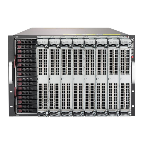
Page 12: Front Features
SuperServer 7089P-TR4T User's Manual Front Features The SC718SAC-R4800 is a 7U chassis. See the illustration below for the features included on the front of the chassis. Figure 1-3. Chassis Front View Front Chassis Features Item Feature Description Eight CPU modules (designated CPU1-CPU8) for CPU, memory, NVMe, PCI-E CPU Modules card and GPU. -
Page 13: Rear Features
Chapter 1: Introduction Rear Features The illustration below shows the features included on the rear of the chassis. From CPU8 From CPU6 From CPU4 From CPU7 From CPU5 Figure 1-4. Chassis Rear View Rear Chassis Features Item Feature Description PCI-E Modules Hot-plug* PCI-E modules 1 through 5 (#1 = PCIE module 1, etc.) 6-13 Hot-swap Fans... -
Page 14: Cpu Board Layout
SuperServer 7089P-TR4T User's Manual 1.5 CPU Board Layout Below is a layout of the X11OPi with connector locations shown. See the table below for descriptions. Figure 1-5. CPU Board Layout... -
Page 15: Location Of The X11Opi Board
Chapter 1: Introduction Location of the X11OPi Board X11OPi-CPU Board BPN-X11OPi Midplane X11OPi Board Figure 1-6. One (1) CPU Board on the Front Side of the 7089P-TR4T Midplane Figure 1.7. Eight (8) CPU Boards (max.) on the Front Side of the 7089P-TR4T Midplane... -
Page 16: Major Components On The X11Opi Board
SuperServer 7089P-TR4T User's Manual Major Components on the X11OPi Board J6 J4 JPWR4 JPWR3 JPWR5 NVME3 NVME2 NVME1 NVME0 Figure 1-8. CPU Board Major Components Connectors on the X11OPi Connector Description J3/J6 High speed interconnect J2/J4 High speed interconnect PCI-E 3.0 x16 slot supported by the CPU (Slot1) PCI-E 3.0 x16 slot supported by the CPU (Slot2) -
Page 17: Processor And Memory Support On The X11Opi
Notes: 1. Memory speed support depends on the CPUs used in the motherboard. For the DIMMF1/F2 latest CPU/memory updates, please refer to our website at http://www.supermicro.com/ products/motherboard. 2. Please refer to the memory configuration & population tables to maximize memory performance. -
Page 18: Aom-X11Opi-Lbg Layout
SuperServer 7089P-TR4T User's Manual 1.6 AOM-X11OPi-LBG Layout Your system comes with the AOM-X11OPi-LBG card, which is to be installed on the BPN- X11OPi midplane. This section provides the information on the Intel PCH add-on module. Below is a layout of the AOM-X11OPi-LBG with connector locations shown. See the table on the following page for descriptions. -
Page 19: Location Of The Aom-X11Opi-Lbg Card
Chapter 1: Introduction Location of the AOM-X11OPi-LBG Card AOM-X11OPi-LBG Card AOM-X11OPi-LBG Card on the Reverse side of the Midplane BPN-X11OPi Midplane (Reverse Side) Figure 1-11. AOM-X11OPi-LBG Card on the Reverse Side of the 7089P-TR4T Midplane... -
Page 20: Major Components On The Aom-X11Opi-Lbg Card
SuperServer 7089P-TR4T User's Manual Major Components on the AOM-X11OPi-LBG Card The locations of the major components on the AOM-X11OPi-LBG card are shown below. UID Switch IPMI LAN LED1 UID LED JUIDB1 IPMI LAN Battery (BT1) TPM/Port80 RAID Key BIOS BMC LED SIOM: CPU3 PCIE 3.0x16... -
Page 21: Quick Reference To The Components On The Aom-X11Opi-Lbg
DVD ROM power header (optional) JRK1 RAIDKey header JSD1/JSD2 Power Connectors 1/2 for I-SATA DOM (Disk_on_Module) devices SIOM (Super I/O Module) PCI-E 3.0 x16 slot supported by CPU3 for use of a Supermicro- JSIOM1 proprietary add-on card JTPM1 TPM (Trusted Platform Module)/Port 80 header JUSB1 Type A USB 3.0 header with support of USB 3.0 Port1, USB 2.0 Port2... -
Page 22: Rsc-X11Opi-Pcie Card
SuperServer 7089P-TR4T User's Manual 1-7 RSC-X11OPi-PCIE Card This section provides the information on the RSC-X11OPi-PCIE add-on card. RSC-X11OPi-PCIE Connectors (5) BPN-X11OPi Midplane (Reverse Side) Figure 1-13. RSC-X11OPi-PCIE Card Layout (Reverse Side) Location of the RSC-X11OPi-PCIE Cards RSC-X11OPi-PCIE (PCI-E Card) (5 Max.) -
Page 23: Major Components On The Rsc-X11Opi-Pcie Card
Chapter 1: Introduction Five (5) RSC-X11OPi-PCIE on the Rear side of Midplane BPN-X11OPi Midplane (Reverse Side) Figure 1-15. RSC-X11OPi-PCIE Card on the Reverse Side of the 7089P-TR4T Midplane (w/5 PCI-E Cards max.) Major Components on the RSC-X11OPi-PCIE Card RSC-X11OPi-PCIE BAR CODE Rev. -
Page 24: Rsc-Blg-E16R Card
SuperServer 7089P-TR4T User's Manual 1-8 RSC-BLG-E16R Card This section provides the information on the RSC-BLG-E16R add-on card. Figure 1-18. RSC-BLG-E16R Card Layout (Front) Figure 1-19. RSC-BLG-E16R Card Layout (Rear) Major Components on the RSC-X11OPi-PCIE Location Description Detailed Description Front Side JPCIE1 PCI-E JPCIE1: PCI-E 3.0 x16 slot... -
Page 25: Rsc-S-6-Op Card
Chapter 1: Introduction 1-9 RSC-S-6-OP Card This section provides the information on the RSC-S-6-OP add-on card. Figure 1-20. RSC-S-6-OP Card Layout (Front) Figure 1-21. RSC-S-6-OP Card Layout (Rear) Major Components on the RSC-X11OPi-PCIE Location Description Detailed Description Front Side SLOT1 PCI-E Slot1: PCI-E 3.0 x16 slot... -
Page 26: Aom-X11Opi-Hdd Card
SuperServer 7089P-TR4T User's Manual 1-10 AOM-X11OPi-HDD Card This section provides the information on the AOM-X11OPi-HDD add-on card. Slot2 PCI-E 3.0 x8 in x16 (J7) SLOT2 PCI-E 3.0 X8 (IN X16) SLOT1 PCI-E 3.0 X8 (IN X16) AOM-X11OPi-HDD REV:1.00 BAR CODE Slot1 PCI-E 3.0 x8 in x16 (J6) -
Page 27: Bpn-X11Opi Midplane
Chapter 1: Introduction 1-11 BPN-X11OPi Midplane This section provides detailed information on the BPN-X11OPi midplane. BPN-X11OPi Rev.1.00 CUT OFF CUT OFF CUT OFF CUT OFF CUT OFF CUT OFF CUT OFF JG17 JG10 JG12 JG14 JG16 JG11 JG15 JG13 Figure 1-23. BPN-X11OPi Midplane Layout (Front Side) HPSXB2: PCIE SLOT1 CPU4 PCI-E 3.0 X16 HPSXB4: PCIE SLOT3... - Page 28 SuperServer 7089P-TR4T User's Manual Figure 1-25. Front View of the BPN-X11OPi Midplane Figure 1-26. Rear View of the BPN-X11OPi Midplane...
-
Page 29: Location Of The Bpn-X11Opi Midplane
Chapter 1: Introduction Location of the BPN-X11OPi Midplane The CPU Board The BPN-X11OPi Midplane (Front Side) Figure 1-27. BPN-X11OPiMidplane (Front Side) The BPN-X11OPi Midplane (Reverse Side) Power Supply Figure 1-28. BPN-X11OPi Midplane (Rear Side) -
Page 30: Major Components On The Bpn-X11Opi Midplane
SuperServer 7089P-TR4T User's Manual Major Components on the BPN-X11OPi Midplane Components on the Front Side of the Midplane The following section provides detailed information of the major components on the front side of the BPN-X11OPi midplane. Please note that all CPU boards and HDD card are installed on the front side of the midplane, and can be accessed from the front side of your system. -
Page 31: Major Components On The Rear Side Of The Bpn-X11Opi Midplane
Chapter 1: Introduction Major Components on the Rear Side of the BPN-X11OPi Midplane The following section provides the information of the major components on the reverse side of the BPN-X11OPi midplane. Please note that the PCH card, PCI-E card, power supply modules, and cooling fans are installed on the reverse side of the midplane, and can be accessed from the rear side of your system. -
Page 32: Major Reverse Side Components Of The Bpn-X11Opi Midplane
SuperServer 7089P-TR4T User's Manual Major Reverse Side Components of the BPN-X11OPi Midplane Major Components on the Reverse Side of the BPN-X11OPi Item# Location Detailed Description J51/J52/J54/J55/J56 PCH Board Slot (SIOM) CPU1/CPU3 PCI-E 3.0 x16 Slot (for the AOM- X11OPi-LBG) HPSXB2: Slot1 CPU4 PCI-E 3.0 x 16 HPSXB3: Slot2 CPU5 PCI-E 3.0 x 16... -
Page 33: Bpn-Sas3-213A Midplane
Chapter 1: Introduction 1-12 BPN-SAS3-213A Midplane This section provides detailed information on the BPN-SAS3-213A midplane. Figure 1-31. BPN-SAS3-213A Midplane Image (Front Side) Major Front Side Components of the BPN-SAS3-213A Midplane Major Components on the Front Side of the BPN-SAS3-213A Item# Description Detailed Description JP3, JP4, JP5 and JP6... -
Page 34: System Block Diagram
SuperServer 7089P-TR4T User's Manual 1-13 System Block Diagram This section provides a detailed block diagram of the system. UPI 10.4GT/s CPU7 PCIE X16, X16, X16 CPU3 PCIE X16, X16, X16 CPU6 PCIE X16, X16, X16 CPU1 PCIE X16, X16, X16 DDR4 CH.A... -
Page 35: Chapter 2 Server Installation
SuperServer 7089P-TR4T User's Manual Chapter 2 Server Installation 2.1 Overview This chapter provides advice and instructions for mounting your system in a server rack. If your system is not already fully integrated with processors, system memory etc., refer to Chapter 4 for details on installing those specific components. -
Page 36: Server Precautions
Chapter 2: Server Installation • Always make sure the rack is stable before extending a server or other component from the rack. • You should extend only one server or component at a time - extending two or more simul- taneously may cause the rack to become unstable. -
Page 37: Circuit Overloading
SuperServer 7089P-TR4T User's Manual Circuit Overloading Consideration should be given to the connection of the equipment to the power supply circuitry and the effect that any possible overloading of circuits might have on overcurrent protection and power supply wiring. Appropriate consideration of equipment nameplate ratings should be used when addressing this concern. -
Page 38: Installing The System Into A Rack
Chapter 2: Server Installation 2.3 Installing the System Into a Rack This section provides information on installing the system into a rack. There are a variety of rack units on the market, meaning the procedure may differ slightly. Refer to the Enclosure Template that was included with the system for help. - Page 39 SuperServer 7089P-TR4T User's Manual 3. The two rail sections are screwed together to keep them immobile during shipping. Release these screws just enough to allow the rails to slide apart. Note the arrow on the rail, which indicates the end that attaches to the front of the rack.
- Page 40 Chapter 2: Server Installation Figure 2-3. Attaching the Optional Handles WARNING: Be sure that the system is empty of all CPU modules, storage modules, power supplies, PCI-E modules and the PCH module BEFORE lifting (as shown in the figure above with the chassis empty).
-
Page 41: Chapter 3 Maintenance And Component Installation
Chapter 3: Maintenance and Component Installation Chapter 3 Maintenance and Component Installation This chapter provides instructions on installing and replacing main system components. To prevent compatibility issues, only use components that match the specifications and/or part numbers given. Installation or replacement of most components require that power first be removed from the system. -
Page 42: Cpu Modules
SuperServer 7089P-TR4T User's Manual 3.3 CPU Modules Removing/Installing a CPU Module 1. Begin by removing power from the system as described in Section 3-1. 2. Pull the top thumb lock outward while slightly lifting the top lever. Repeat this procedure for the bottom thumb lock and lever. -
Page 43: Installing The Xeon Intel® 81Xx Series Processor On The X11Opi-Cpu Board
When receiving a system without a processor pre-installed, make sure that the plastic CPU socket cap is in place and that none of the socket pins are bent; otherwise, contact your retailer immediately. Refer to the Supermicro website for updates on CPU support. The Intel® 81xx series Series Processor Note: All graphics shown in this manual were based upon the latest PCB revision available at the time of publishing this manual. -
Page 44: Overview Of The Processor Socket Assembly
SuperServer 7089P-TR4T User's Manual Overview of the Processor Socket Assembly The processor socket assembly contains 1) Intel Xeon Intel® 81xx series processor (Note below), 2) the narrow processor clip, 3) the dust cover, and 4) the CPU socket Notes: Intel Intel® 81xx series series processors contain the F model and the non-F model processors. -
Page 45: Overview Of The Processor Heatsink Module (Phm)
Chapter 3: Maintenance and Component Installation Overview of the Processor Heatsink Module (PHM) The Processor Heatsink Module (PHM) contains 1) a heatsink, 2) a narrow processor clip, and 3) the Intel Intel® 81xx series processor. 1. Heatsink 2. Narrow processor clip 3. -
Page 46: Attaching The Intel Intel® 81Xx Series Processor To The Narrow Processor Clip To Create The Processor Package Assembly
SuperServer 7089P-TR4T User's Manual Attaching the Intel Intel® 81xx series Processor to the Narrow Processor Clip to Create the Processor Package Assembly 1. Locate pin 1 (notch A), which is the triangle located on the top of the narrow processor clip. -
Page 47: Attaching The Processor Package Assembly To The Heatsink To Form The Processor Heatsink Module (Phm)
Chapter 3: Maintenance and Component Installation Attaching the Processor Package Assembly to the Heatsink to Form the Processor Heatsink Module (PHM) After you have made a processor package assembly by following the instructions on the previous page, please follow the steps below to mount the processor package assembly onto the heatsink to create the Processor Heatsink Module (PHM). -
Page 48: Preparing The Cpu Socket For Installation
SuperServer 7089P-TR4T User's Manual Preparing the CPU Socket for Installation This motherboard comes with the CPU socket pre-assembled in the factory. The CPU socket contains 1) a dust cover, 2) a socket bracket, 3) the CPU socket, and 4) a back plate. These components are pre-installed on the motherboard before shipping. -
Page 49: Installing The Processor Heatsink Module (Phm)
Chapter 3: Maintenance and Component Installation Installing the Processor Heatsink Module (PHM) 1. Once you have assembled the processor heatsink module (PHM), you are ready to install the processor heatsink module (PHM) into the CPU socket on the motherboard. To install the PHM into the CPU socket, follow the instructions below. 2. -
Page 50: Removing The Processor Heatsink Module (Phm) From The Motherboard
SuperServer 7089P-TR4T User's Manual Removing the Processor Heatsink Module (PHM) from the Motherboard Before removing the processor heatsink module (PHM), unplug power cord from the power outlet. 1. Using a T30 Torx-bit screwdriver, turn the screws on the PHM counterclockwise to loosen them from the socket, starting with screw marked #4 (in the sequence of 4, 3, 2, 2. -
Page 51: Memory Support And Installation
Chapter 3: Maintenance and Component Installation Memory Support and Installation Note: Check the Supermicro website for recommended memory modules. Memory Support Each CPU board supports up to 1.5 TB of DDR4 3DS Load Reduced (3DS LRDIMM), Load Reduced (LRDIMM), or Registered (RDIMM) ECC 2666 Mhz memory in 12 slots. With eight... -
Page 52: Memory Support Tables
SuperServer 7089P-TR4T User's Manual Memory Support Tables DDR4 Memory Support for the Intel Intel® 81xx series Processor Platform Speed (MT/s); Voltage (V); Slots per Channel (SPC) and DIMMs per Channel (DPC) Ranks DIMM Capacity (GB) Per DIMM 2 Slots per Channel... -
Page 53: Installing Dimm Modules On The X11Opi-Cpu Board
CAUTION Exercise extreme care when installing or removing DIMM modules to prevent any possible damage. Check Supermicro's website for recommended memory modules. 1. Install the desired number of DIMM modules on the CPU board; each board supports up to 12 DIMMs. When installing memory, be sure to always populate the blue slots first, starting with DIMMA1, DIMMB1, DIMMC1, DIMMD1, DIMME1, and DIMMF1. -
Page 54: Pci-E Expansion Card Installation
SuperServer 7089P-TR4T User's Manual 3.4 PCI-E Expansion Card Installation The 7089P-TR4T supports up to twenty-three (23) PCI-E 3.0 slots: five (5) are in the rear five (5) PCI-E modules, sixteen (16) are in the eight (8) front CPU modules, two (2) are inside the storage module. - Page 55 Chapter 3: Maintenance and Component Installation 5. Press and rotate the silver locking tab to fully release the PCI-E card. 6. Pull the card out of the PCI-E board. Figure 3-3. Removing a PCI-E Module...
- Page 56 SuperServer 7089P-TR4T User's Manual Figure 3-4. Removing a PCI-E Card from a PCIE Module...
- Page 57 Chapter 3: Maintenance and Component Installation Adding a Hot-Plug PCI-E Card 1. Insert the PCI-E card into the PCIE board, making sure the card bracket aligns with the optional screw hole. 2. Secure the PCI-E card by locking the silver locking tab. Insert the PCI-E module back to the chassis and fully close the lever before locking it by pushing the red release tab to left.
-
Page 58: Cpu Module
SuperServer 7089P-TR4T User's Manual CPU Module Perform the following steps to install a PCI-E card in any of the eight CPU modules at the front of the system. Power must be removed from the system (as described in Section 3.1) when performing this procedure. - Page 59 Chapter 3: Maintenance and Component Installation Figure 3-6. Installing a PCI-E Card in a CPU Module...
- Page 60 SuperServer 7089P-TR4T User's Manual Figure 3-7. Installing a PCI-E Card in a CPU Module (cont.)
-
Page 61: Storage Module
Chapter 3: Maintenance and Component Installation Storage Module Perform the following steps to install a PCI-E card in the HDD storage module at the front of the system. Power must be removed from the system as described in Section 3.1 when performing this procedure. - Page 62 SuperServer 7089P-TR4T User's Manual Figure 3-9. Installing a PCI-E Card in a Storage Module...
-
Page 63: Onboard Battery
Chapter 3: Maintenance and Component Installation 3.5 Onboard Battery The system uses non-volatile memory to retain system information when system power is removed. This memory is powered by a lithium battery on the PCH board. Replacing the Battery 1. Begin by removing power from the system as described in Section 3-1. 2. - Page 64 SuperServer 7089P-TR4T User's Manual Figure 3-11. Installing the Battery...
-
Page 65: Chassis Components
Chapter 3: Maintenance and Component Installation 3.6 Chassis Components Hot-Swap Hard Drives The 7089P-TR4T includes one storage module that supports sixteen (16) 2.5" which can be removed without powering down the system. Only enterprise level SAS or SATA HDDs are recommended. -
Page 66: Hard Drive Carrier Indicators
SuperServer 7089P-TR4T User's Manual Installing a Hard Drive into a Drive Carrier 1. Insert a drive into the carrier with the PCB side facing down and the connector end toward the rear of the carrier. 2. Align the drive in the carrier so that the mounting holes of both are aligned. Note that there are holes in the carrier marked "SAS"... -
Page 67: Internal Hard Drives
Chapter 3: Maintenance and Component Installation Internal Hard Drives The storage module in the 7089P-TR4T supports up to six 3.5" or eight 2.5" fixed HDDs. Installing or removing these drives requires the module to be removed from the chassis. Removing a Storage Module 1. -
Page 68: Removing/Installing Internal Hard Drives
SuperServer 7089P-TR4T User's Manual Removing/Installing Internal Hard Drives To remove the cover of the storage module, depress the two release buttons and push the cover toward the rear of the module as shown below. 2.5" HDDs The 2.5" hard drives are mounted in brackets or directly secured to the bottom of the storage module tray. - Page 69 Chapter 3: Maintenance and Component Installation Figure 3-16. Installing/Removing 2.5" HDDs with bracket...
- Page 70 SuperServer 7089P-TR4T User's Manual 3.5" HDDs The 3.5" hard drives are mounted in brackets or directly secured to the bottom of the storage module tray. See Figure 3-17 for the case without brackets. 1. Remove the bracket (if any) holding the drive you wish to replace by unscrewing from the bottom of the storage module.
-
Page 71: System Cooling
Chapter 3: Maintenance and Component Installation System Cooling Eight hot-swapable 9-cm counter-rotating fans at the rear of the chassis provide the cooling for the system. Each fan unit is made up of two fans joined back-to-back, which rotate in opposite directions. This counter-rotating action generates exceptional airflow and is effective in dampening vibration levels. -
Page 72: Power Supply
If a power supply unit fails, the others will take on the load to allow the system to continue operation without interruption. The amber Power Fail LED will illuminate and remain on until the failed unit has been replaced. Replacement units can be ordered directly from Supermicro (see contact information in the Preface). -
Page 73: Chapter 4 Board Connections
Chapter 4: Board Connections Chapter 4 Board Connections This section describes the connections on the various boards in the system and provides pinout definitions. The LEDs on the motherboard are also described here. A severboard layout indicating component locations may be found in Appendix B. Please review the Safety Precautions in Chapter 3 before installing or removing components. -
Page 74: Aom-X11Opi-Lbg Connections, Jumpers And Leds
SuperServer 7089P-TR4T User's Manual NVM Express Connections Two NVM Express ports are located on the serverboard. JNVME ports 1/2 provide high-speed, low-latency PCI-Exp. 3.0 x4 connections directly from the CPU to NVMe Solid State (SSD) drives. This greatly increases SSD data-throughput performance and significantly reduces PCI-E latency by simplifying driver/software requirements resulted from direct PCI-E interface from the CPU to the NVMe SSD drives. - Page 75 Chapter 4: Board Connections VGA Enable Jumper JPG1 allows the user to enable or the VGA support in your system. The default setting is "1-2" to enable the connection. Refer to the table below for jumper settings. VGA Enable Jumper Settings Jumper Setting Definition Enabled (Default)
-
Page 76: Headers And Connectors
I-SATA 3/4 & M.2 Connectors Two-SATA 3.0 connectors (I-SATA 3/4) are located on the AOM-X11OPi-LBG. These SATA ports are supported by the Intel PCH chip and are used with Supermicro SuperDOM (Disk- on-Module) connectors with power-pins built in. The SuperDOM connectors are backward- compatible with regular SATA HDDs and SATA DOMs. - Page 77 Chapter 4: Board Connections Universal Serial Bus (USB) An internal USB header, located at JUSB1, provides two USB 2.0 connections (USB 5/USB6) for your system. In addition, a Type A 3.0 header (JUSB2) also provides USB 3.0 Port 1 and USB 2.0 Port 2 connections for internal access.
- Page 78 SuperServer 7089P-TR4T User's Manual DOM Power Connectors Two power connectors for SATA DOM (Disk_On_Module) devices are located at JSD1/JSD2. Connect appropriate cables here to provide power support for your Serial Link DOM devices. DOM PWR Pin Definitions Pin# Definition Ground Ground RAID Key The Intel RAID key header (JRK1) is used to enable RAID support for your system.
-
Page 79: Led Indicators
~3, 4~7) on the AOM-X11OPI-HDD card. These ports, supported by the Intel PCH, provide serial-link signal connections, which are faster than the connections of Parallell ATA. Note: For more information on SATA HostRAID configuration, please refer to the Intel SATA HostRAID User's Guide posted on our Website @ http://www.supermicro.com. -
Page 80: Bpn-X11Opi Connections
SuperServer 7089P-TR4T User's Manual 4.4 BPN-X11OPi Connections Fan Headers There are 16 system/CPU fan headers (Fans 1-8_1) on reverse side of the BPN-X11OPi midplane. All these 4-pin fans headers are backward-compatible with the traditional 3-pin fans. However, fan speed control is available for 4-pin fans only by Thermal Management via the IPMI 2.0 interface. -
Page 81: Chapter 5 Software
USB/SATA DVD drive, or a USB flash drive, or the IPMI KVM console. 2. Retrieve the proper RST/RSTe driver. Go to the Supermicro web page for your motherboard and click on "Download the Latest Drivers and Utilities", select the proper driver, and copy it to a USB flash drive. - Page 82 SuperServer 7089P-TR4T User's Manual 4. During Windows Setup, continue to the dialog where you select the drives on which to install Windows. If the disk you want to use is not listed, click on “Load driver” link at the bottom left corner.
-
Page 83: Driver Installation
The Supermicro website contains drivers and utilities for your system at https://www. supermicro.com/wftp/driver. Some of these must be installed, such as the chipset driver. After accessing the website, go into the CDR_Images (in the parent directory of the above link) and locate the ISO file for your motherboard. Download this file to to a USB flash drive or a DVD. -
Page 84: Superdoctor ® 5
5.3 SuperDoctor ® The Supermicro SuperDoctor 5 is a program that functions in a command-line or web-based interface for Windows and Linux operating systems. The program monitors such system health information as CPU temperature, system voltages, system power consumption, fan speed, and provides alerts via email or Simple Network Management Protocol (SNMP). -
Page 85: Ipmi
The X11OPi supports the Intelligent Platform Management Interface (IPMI). IPMI is used to provide remote access, monitoring and management. There are several BIOS settings that are related to IPMI. For general documentation and information on IPMI, please visit our website at: http://www.supermicro.com/products/nfo/IPMI.cfm. -
Page 86: Chapter 6 Uefi Bios
SuperServer 7089P-TR4T User's Manual Chapter 6 UEFI BIOS 3-1 Introduction This chapter describes the UEFI BIOS Setup utility for the X11OPi-CPU motherboard. The BIOS is stored on a chip and can be easily upgraded using a flash program. Note: Due to periodic changes to the BIOS, some settings may have been added or deleted and might not yet be recorded in this manual. -
Page 87: Main Setup
Note: The time is in the 24-hour format. For example, 5:30 P.M. appears as 17:30:00. The date's default value is 01/01/2014 after RTC reset. Supermicro X11OPi BIOS Version This item displays the version of the BIOS ROM used in the system. -
Page 88: Advanced Setup Configurations
SuperServer 7089P-TR4T User's Manual Total Memory This item displays the total size of memory available in the system. Memory Speed This item displays the default speed of the memory modules installed in the system. 6-3 Advanced Setup Configurations Use the arrow keys to select the Advanced submenu and press <Enter> to access the submenu items: Warning: Take Caution when changing the Advanced settings. - Page 89 Chapter 6: BIOS Bootup NumLock State Use this feature to set the Power-on state for the Numlock key. The options are Off and On. Interrupt 19 Trap Capture Interrupt 19 is the software interrupt that handles the boot disk function. When this item is set to Immediate, the ROM BIOS of the host adaptors will "capture"...
- Page 90 SuperServer 7089P-TR4T User's Manual CPU Configuration Warning: Setting the wrong values in the features below may cause the system to malfunction. Processor Configuration The following CPU information will be displayed: Processor BSP Revision Processor Socket Processor ID Processor Frequency Processor Max Ratio...
- Page 91 Chapter 6: BIOS Hardware Prefetcher (Available when supported by the CPU) If this feature is set to Enable, the hardware prefetcher will prefetch streams of data and instructions from the main memory to the Level 2 (L2) cache to improve CPU performance. The options are Disable and Enable.
- Page 92 SuperServer 7089P-TR4T User's Manual Advanced Power Management Configuration Super Performance Mode Select Enable to support Super Performance mode to enhance system performance. The options are Disable and Enable. CPU P State Control SpeedStep (PStates) EIST (Enhanced Intel SpeedStep Technology) allows the system to automatically adjust processor voltage and core frequency in an effort to reduce power consumption and heat dissipation.
- Page 93 Chapter 6: BIOS CPU C6 Report Select Enable to allow the BIOS to report the CPU C6 state (ACPI C3) to the operating system. During the CPU C6 state, power to all caches is turned off. The options are Auto, Enable, and Disable.
- Page 94 SuperServer 7089P-TR4T User's Manual Degrade Precedence Use this feature to select the degrading precedence option for Ultra Path Interconnect (UPI) connections. Select Topology Precedent to degrade UPI features if system options are in conflict. Select Feature Precedent to degrade UPI topology if system options are in conflict.
- Page 95 Chapter 6: BIOS Data Scrambling for DDR4 Select Enable to enable data scrambling for DDR4 memory to enhance system performance and security. The options are Auto, Disable, and Enable. tCCD_L Relaxation If this feature is set to Enable, SPD (Serial Presence Detect) will override tCCD_L ("Column to Column Delay-Long", or “Command to Command Delay-Long”...
- Page 96 SuperServer 7089P-TR4T User's Manual Memory Map Use this submenu to configure the following Memory Map settings. Volatile Memory Mode Select 1LM to use 1LM memory mode for volatile memory modules installed in the system. Select 2LM to use 2LM memory mode for volatile memory modules installed in the system.
- Page 97 Chapter 6: BIOS Mirror Mode Use this feature to configure the mirror mode settings for all 1LM/2LM memory modules installed in the system which will create a duplicate copy of data stored in the memory to increase memory security, but it will reduce the memory capacity into half. The options are Disable, Mirror Mode 1LM, and Mirror Mode 2LM.
- Page 98 SuperServer 7089P-TR4T User's Manual Socket 1 Configuration - Socket 8 Configuration IOU0 (IIO PCIe Br1) This feature configures the PCI-E Bifuraction setting for a PCI-E port specified by the user. The options are x4x4x4x4, x4x4x8, x8x4x4, x8x8, x16, and Auto. IOU1 (IIO PCIe Br2) This feature configures the PCI-E Bifuraction setting for a PCI-E port specified by the user.
- Page 99 Chapter 6: BIOS Sck1 (Socket1) IOAT Configuration- Sck8 (Socket 8) IOAT Configuration Select Enable to enable DAC support. The default setting is Disable. IOAT Function 0 Items - IOAT Function 7 Items DMA (Direct Memory Access) Select Enable to enable DMA support. The default setting is Enable. No Snoop Select Enable to enable No Snoop support.
- Page 100 SuperServer 7089P-TR4T User's Manual PassThrough DMA Select Enable for the Non-Iscoh VT-d engine to pass through DMA (Direct Memory Access) to enhance system performance. The options are Enable and Disable. Select Enable to enable ATS (Address Translation Services) support for the Non-Iscoh VT-d engine to enhance system performance.
- Page 101 Chapter 6: BIOS Legacy USB Support Select Enabled to support onboard legacy USB devices. Select Auto to disable legacy support if there are no legacy USB devices present. Select Disable to have all USB devices available for EFI applications only. The options are Enabled, Disabled and Auto. XHCI Hand-Off This is a work-around solution for operating systems that do not support XHCI (Extensible Host Controller Interface) hand-off.
- Page 102 SuperServer 7089P-TR4T User's Manual Configure SATA as (Available when the item above: SATA Controller is set to enabled) Select AHCI to configure a SATA drive specified by the user as an AHCI drive. Select RAID to configure a SATA drive specified by the user as a RAID drive. The options are AHCI and RAID.
- Page 103 Chapter 6: BIOS (PCH) sSATA Configuration When this submenu is selected, AMI BIOS automatically detects the presence of the sSATA devices that are supported by the PCH sSATA controller and displays the following items: sSATA Controller This item enables or disables the onboard sSATA controller supported by the Intel SCU. The options are Enable and Disable.
- Page 104 SuperServer 7089P-TR4T User's Manual sSATA Device Type Use this item to specify if the device installed on the sSATA port specified by the user should be connected to a Solid State drive or a Hard Disk Drive. The options are Hard Disk Drive and Solid State Drive.
- Page 105 Chapter 6: BIOS Onboard Video OPROM (Option ROM)/SIOM Module OPROM/NVMe Module OPROM/ GPU OPROM/HDD OPROM Use this feature to configure the Option ROM type for the device installed in the slot specified by the user for system boot. The options are Disabled, Legacy and EFI. PCIE Module Slot1 x16 OPROM (Option ROM)/PCIE Module Slot2 x16 OPROM/PCIE Module Slot3 x16 OPROM/PCIE Module Slot4 x16 OPROM/ PCIE Module Slot5 x16 OPROM...
- Page 106 SuperServer 7089P-TR4T User's Manual Super IO Configuration Super IO Chip AST2500 Serial Port 1 Configuration Serial Port Select Enabled to enable the onboard serial port specified by the user. The options are Enabled and Disabled. Device Settings This feature displays the base I/O port address and the Interrupt Request address of a serial port specified by the user.
- Page 107 Chapter 6: BIOS Serial Port 2 Attribute Select SOL to use COM Port 2 as a Serial_Over_LAN (SOL) port for console redirection. The options are COM and SOL. Serial Port Console Redirection COM 1 Console Redirection Select Enabled to enable COM Port 1 for Console Redirection, which will allow a client machine to be connected to a host machine at a remote site for networking.
- Page 108 SuperServer 7089P-TR4T User's Manual Flow Control Use this feature to set the flow control for Console Redirection to prevent data loss caused by buffer overflow. Send a "Stop" signal to stop sending data when the receiving buffer is full. Send a "Start" signal to start sending data when the receiving buffer is empty. The options are None and Hardware RTS/CTS.
- Page 109 Chapter 6: BIOS Console Redirection Settings (for SOL/COM2) Use this feature to specify how the host computer will exchange data with the client computer, which is the remote computer used by the user. Terminal Type Use this feature to select the target terminal emulation type for Console Redirection. Select VT100 to use the ASCII Character set.
- Page 110 SuperServer 7089P-TR4T User's Manual Recorder Mode Select Enabled to capture the data displayed on a terminal and send it as text messages to a remote server. The options are Disabled and Enabled. Resolution 100x31 Select Enabled for extended-terminal resolution support. The options are Disabled and Enabled.
- Page 111 Chapter 6: BIOS EMS Console Redirection Settings Out-of-Band Management Port The feature selects a serial port in a client server to be used by the Windows Emergency Management Services (EMS) to communicate with a remote host server. The options are COM1 (Console Redirection) and COM2/SOL (Console Redirection).
- Page 112 SuperServer 7089P-TR4T User's Manual High Precision Timer Select Enabled to activate the High Precision Event Timer (HPET) that produces periodic interrupts at a much higher frequency than a Real-time Clock (RTC) does in synchronizing multimedia streams, providing smooth playback and reducing the dependency on other timestamp calculation devices, such as an x86 RDTSC Instruction embedded in the CPU.
- Page 113 Chapter 6: BIOS If this option is set to Enable, the following screen and items will display: • Active PCR Banks • Available PCR Banks Pending Operation Use this feature to schedule a TPM-related operation to be performed by a security (TPM) device at the next system boot to enhance system data integrity.
- Page 114 SuperServer 7089P-TR4T User's Manual TXT Support Select Enabled to enable Intel Trusted Execution Technology (TXT) support to enhance system security and data integrity. The options are Disabled and Enabled. Note 1: If the option for this item (TXT Support) is set to Enabled, be sure to disable EV DFX (Device Function On-Hide) support for the system to work properly.
-
Page 115: Event Logs
Chapter 6: BIOS 6-4 Event Logs Use this feature to configure Event Log settings. Change SMBIOS Event Log Settings Enabling/Disabling Options SMBIOS Event Log Select Enabled to enable SMBIOS (System Management BIOS) Event logging during system boot. The options are Enabled and Disabled. Erasing Settings Erase Event Log Select Enabled to erase all error events in the SMBIOS (System Management BIOS) log... - Page 116 SuperServer 7089P-TR4T User's Manual MECI (Multiple Event Count Increment) Enter the increment value for the multiple event counter. Enter a number between 1 to 255. The default setting is 1. METW (Multiple Event Count Time Window) Use this feature to determine how long (in minutes) the multiple event counter should wait before generating a new event log.
-
Page 117: Ipmi
Chapter 6: BIOS 6-5 IPMI Use this feature to configure Intelligent Platform Management Interface (IPMI) settings. When you select this submenu and press the <Enter> key, the following information will display: • IPMI Firmware Revision: This feature indicates the IPMI firmware revision used in your system. - Page 118 SuperServer 7089P-TR4T User's Manual When SEL is Full This feature allows the user to determine what the BIOS should do when the system event log is full. Select Erase Immediately to erase all events in the log when the system event log is full.
- Page 119 Chapter 6: BIOS Update IPMI LAN Configuration Select Yes for the BIOS to implement all IP/MAC address changes at the next system boot. The default setting is No. If this option is set to Yes, the following items will display. IPMI LAN Selection (Available when Update IPMI LAN Configuration is set to Yes) Use this feature to configure the IPMI LAN mode setting. The options are Dedicated, Shared, and Failover.
-
Page 120: Security Settings
SuperServer 7089P-TR4T User's Manual 6-6 Security Settings This menu allows the user to configure the following security settings for the system. Administrator Password Use this feature to set the administrator password which is required to enter the BIOS setup utility. The length of the password should be from 3 characters to 20 characters long. - Page 121 Chapter 6: BIOS Attempt Secure Boot If this feature is set to Enabled, the BIOS will attempt to use secure boot settings for system boot. A Platform Key is a security key used to manage the security settings of the platform firmware used in your system.
- Page 122 SuperServer 7089P-TR4T User's Manual Key Exchange Keys This feature allows the user to enter and configure a set of values to be used as a Key- Exchange-Keys for the system. This set of values also indicate the size, the keys numbers, and the key source of the Key-Exchange-Keys.
-
Page 123: Boot Settings
Chapter 6: BIOS 6-7 Boot Settings Use this feature to configure Boot Settings: Boot Mode Select Use this feature to select the type of devices to be used for system boot. The options are Legacy, UEFI (Unified Extensible Firmware Interface), and Dual. Fixed Boot Order Priorities This feature prioritizes the order of a bootable device from which the system will boot. - Page 124 SuperServer 7089P-TR4T User's Manual Add New Boot Option This feature allows the user to add a new boot option to the boot priority features for your system. Add Boot Option Use this feature to specify the name for the new boot option.
- Page 125 Chapter 6: BIOS Delete Drive Option Select the target boot driver to delete from the boot priority list. Hard Disk Drive BBS Priorities • Boot Option #1 - #5 Network Drive BBS Priorities • Boot Option #1 USB Key Drive BBS Priorities •...
-
Page 126: Save & Exit
SuperServer 7089P-TR4T User's Manual 6-8 Save & Exit Select the Save & Exit tab from the BIOS setup screen to configure the settings below. Save Options Discard Changes and Exit Select this option to quit the BIOS setup without making any permanent changes to the system configuration and reboot the computer. - Page 127 Chapter 6: BIOS Default Options Restore Optimized Defaults To set this feature, select Restore Defaults from the Exit menu and press <Enter> to load manufacturer default settings which are intended for maximum system performance but not for maximum stability. Save As User Defaults To set this feature, select Save as User Defaults from the Exit menu and press <Enter>.
-
Page 128: Appendix A Bios Error Codes
SuperServer 7089P-TR4T User's Manual Appendix A BIOS Error Codes A-1 BIOS Error Beep (POST) Codes During the POST (Power-On Self-Test) routines, which are performed each time the system is powered on, errors may occur. Non-fatal errors are those which, in most cases, allow the system to continue the boot-up process. - Page 129 When BIOS performs the Power On Self Test, it writes checkpoint codes to I/O port 0080h. If the computer cannot complete the boot process, a diagnostic card can be attached to the computer to read I/O port 0080h (Supermicro p/n AOC-LPC80-20). For information on AMI updates, please refer to http://www.ami.com/products/.
-
Page 130: Appendix B Standardized Warning Statements For Ac Systems
Supermicro's Technical Support department for assistance. Only certified technicians should attempt to install or configure components. Read this appendix in its entirety before installing or configuring components in the Supermicro chassis. These warnings may also be found on our website at http://www.supermicro.com/about/... - Page 131 Appendix B: Standardized Warning Statements Warnung WICHTIGE SICHERHEITSHINWEISE Dieses Warnsymbol bedeutet Gefahr. Sie befinden sich in einer Situation, die zu Verletzungen führen kann. Machen Sie sich vor der Arbeit mit Geräten mit den Gefahren elektrischer Schaltungen und den üblichen Verfahren zur Vorbeugung vor Unfällen vertraut. Suchen Sie mit der am Ende jeder Warnung angegebenen Anweisungsnummer nach der jeweiligen Übersetzung in den übersetzten Sicherheitshinweisen, die zusammen mit diesem Gerät ausgeliefert wurden.
- Page 132 SuperServer 7089P-TR4T User's Manual !تحذٌز جسذٌة اصابة ًتتسبب ف حالة ٌوكي أى ًاًك ف خطز ًٌٌع هذا الزهز الذوائز بالوخاطز الٌاجوة عي ي على علن ، ك هعذات تعول على أي قبل أى الكهزبائٍة حىادث أي وقىع وٌع ل الىقائٍة...
- Page 133 Appendix B: Standardized Warning Statements Warnung Vor dem Anschließen des Systems an die Stromquelle die Installationsanweisungen lesen. ¡Advertencia! Lea las instrucciones de instalación antes de conectar el sistema a la red de alimentación. Attention Avant de brancher le système sur la source d'alimentation, consulter les directives d'installation. מתח...
- Page 134 SuperServer 7089P-TR4T User's Manual Warnung Dieses Produkt ist darauf angewiesen, dass im Gebäude ein Kurzschluss- bzw. Überstromschutz installiert ist. Stellen Sie sicher, dass der Nennwert der Schutzvorrichtung nicht mehr als: 250 V, 20 A beträgt. ¡Advertencia! Este equipo utiliza el sistema de protección contra cortocircuitos (o sobrecorrientes) del edificio.
- Page 135 Appendix B: Standardized Warning Statements Power Disconnection Warning Warning! The system must be disconnected from all sources of power and the power cord removed from the power supply module(s) before accessing the chassis interior to install or remove system components. 電源切断の警告...
- Page 136 SuperServer 7089P-TR4T User's Manual امداد وحدة من سهك انكهرباء وإزانت انطاقت مصادر من جميع اننظاو يجب فصم قبم انطاقت الجهاز مكىناث نتثبيج أو إزانت ههيكم ن انمناطق انداخهيت انىصىل إنى 경고! 시스템에 부품들을 장착하거나 제거하기 위해서는 섀시 내부에 접근하기 전에 반드시 전원...
- Page 137 Appendix B: Standardized Warning Statements Attention Il est vivement recommandé de confier l'installation, le remplacement et la maintenance de ces équipements à des personnels qualifiés et expérimentés. !אזהרה .הציוד או לתת שירות עבור הציוד אי להתקין, להחליף את צוות מוסמך בלבד רש هذا...
- Page 138 SuperServer 7089P-TR4T User's Manual Warnung Diese Einheit ist zur Installation in Bereichen mit beschränktem Zutritt vorgesehen. Der Zutritt zu derartigen Bereichen ist nur mit einem Spezialwerkzeug, Schloss und Schlüssel oder einer sonstigen Sicherheitsvorkehrung möglich. ¡Advertencia! Esta unidad ha sido diseñada para instalación en áreas de acceso restringido. Sólo puede obtenerse acceso a una de estas áreas mediante la utilización de una herramienta especial,...
- Page 139 Appendix B: Standardized Warning Statements Battery Handling Warning! There is the danger of explosion if the battery is replaced incorrectly. Replace the battery only with the same or equivalent type recommended by the manufacturer. Dispose of used batteries according to the manufacturer's instructions 電池の取り扱い...
- Page 140 SuperServer 7089P-TR4T User's Manual فعليل بطريقة غير صحيحة البطارية انفجار في حالة اسحبذال من هناك خطر اسحبذال البطارية به الشرمة المصنعة أوصث مما أو ما يعادلها بنفس النىع فقط حعليمات الشرمة الصانعة المسحعملة وفقا ل جخلص من البطاريات 경고! 배터리가 올바르게 교체되지 않으면 폭발의 위험이 있습니다. 기존 배터리와 동일하거나 제...
- Page 141 Appendix B: Standardized Warning Statements ¡Advertencia! Puede que esta unidad tenga más de una conexión para fuentes de alimentación. Para cortar por completo el suministro de energía, deben desconectarse todas las conexiones. Attention Cette unité peut avoir plus d'une connexion d'alimentation. Pour supprimer toute tension et tout courant électrique de l'unité, toutes les connexions d'alimentation doivent être débranchées.
- Page 142 SuperServer 7089P-TR4T User's Manual Backplane Voltage Warning! Hazardous voltage or energy is present on the backplane when the system is operating. Use caution when servicing. バックプレーンの電圧 システムの稼働中は危険な電圧または電力が、 バックプレーン上にかかっています。 修理する際には注意く ださい。 警告 当系统正在进行时,背板上有很危险的电压或能量,进行维修时务必小心。 警告 當系統正在進行時,背板上有危險的電壓或能量,進行維修時務必小心。 Warnung Wenn das System in Betrieb ist, treten auf der Rückwandplatine gefährliche Spannungen oder Energien auf.
- Page 143 Appendix B: Standardized Warning Statements اللىحة أوالطاقة المىجىدة على التيار الكهزبائي مه خطز هناك هذا الجهاس خدمة كه حذرا عند يعمل النظام عندما يكىن 경고! 시스템이 동작 중일 때 후면판 (Backplane)에는 위험한 전압이나 에너지가 발생 합니다. 서비스 작업 시 주의하십시오. Waarschuwing Een gevaarlijke spanning of energie is aanwezig op de backplane wanneer het systeem in gebruik is.
- Page 144 SuperServer 7089P-TR4T User's Manual תיאום חוקי החשמל הארצי !אזהרה הציוד חייבת להיות תואמת לחוקי החשמל המקומיים והארציים התקנת المتعلقة المحلية والىطىية قىاويه يجب أن يمتثل لل الكهربائية تركيب المعدات بالكهرباء 경고! 현 지역 및 국가의 전기 규정에 따라 장비를 설치해야 합니다.
- Page 145 Appendix B: Standardized Warning Statements Attention La mise au rebut ou le recyclage de ce produit sont généralement soumis à des lois et/ou directives de respect de l'environnement. Renseignez-vous auprès de l'organisme compétent. סילוק המוצר !אזהרה .חוקי המדינה סילוק סופי של מוצר זה חייב להיות בהתאם להנחיות ו القىانين...
- Page 146 SuperServer 7089P-TR4T User's Manual Warnung Gefährlich Bewegende Teile. Von den bewegenden Lüfterblätter fern halten. Die Lüfter drehen sich u. U. noch, wenn die Lüfterbaugruppe aus dem Chassis genommen wird. Halten Sie Finger, Schraubendreher und andere Gegenstände von den Öffnungen des Lüftergehäuses entfernt.
- Page 147 Brand entstehen. Elektrische Geräte und Material Safety Law verbietet die Verwendung von UL-oder CSA-zertifizierte Kabel, UL oder CSA auf der Code für alle anderen elektrischen Geräte als Produkte von Supermicro nur bezeichnet gezeigt haben. ¡Advertencia! Al instalar el producto, utilice los cables de conexión previstos o designados, los cables y adaptadores de CA.
- Page 148 Het gebruik van andere kabels en adapters kan leiden tot een storing of een brand. Elektrisch apparaat en veiligheidsinformatiebladen wet verbiedt het gebruik van UL of CSA gecertificeerde kabels die UL of CSA die op de code voor andere elektrische apparaten dan de producten die door Supermicro alleen.
-
Page 149: Appendix C System Specifications
Appendix C: System Specifications Appendix C System Specifications Processors Eight Intel® 81xx series in an Socket P type socket* Note: Please refer to the motherboard specifications page on our website for updates to supported processors. Chipset Intel C621 chipset BIOS 16 MB AMI® Flash ROM (on AOM-X11OPi-LBG) Memory Each CPU board supports up to 1.5 TB of twelve (12) DDR4 3DS Load Reduced (3DS LRDIMM), Load Re duced (LRDIMM), or Registered (RDIMM) ECC 2666/2400/2133/1866/1600/1333 MHz... - Page 150 SuperServer 7089P-TR4T User's Manual Regulatory Compliance Electromagnetic Emissions: FCC Class A, EN 55032 Class A, EN 61000-3-2/3-3, CISPR 32 Class A Electromagnetic Immunity: EN 55024/CISPR 24, (EN 61000-4-2, EN 61000-4-3, EN 61000-4-4, EN 61000-4-5, EN 61000-4-6, EN 61000-4-8, EN 61000-4-11)
-
Page 151: Appendix D Uefi Bios Recovery
Warning: Do not upgrade the BIOS unless your system has a BIOS-related issue. Flashing the wrong BIOS can cause irreparable damage to the system. In no event shall Supermicro be liable for direct, indirect, special, incidental, or consequential damages arising from a BIOS update. - Page 152 SuperServer 7089P-TR4T User's Manual CD/DVD ROM/RW device can be used for this purpose. However, a USB Hard Disk drive cannot be used for BIOS recovery at this time. The file system supported by the recovery block is FAT (including FAT12, FAT16, and FAT32) which is installed on a bootable or non-bootable USB-attached device.
- Page 153 Appendix D: UEFI BIOS Recovery 3. After locating the healthy BIOS binary image, the system will enter the BIOS Recovery menu as shown below. Note: At this point, you may decide if you want to start the BIOS recovery. If you decide to proceed with BIOS recovery, follow the procedures below.
- Page 154 SuperServer 7089P-TR4T User's Manual Note: Do not interrupt the BIOS flashing process until it has completed. 5. After the BIOS recovery process is complete, press any key to reboot the system. 6. Using a different system, extract the BIOS package into a USB flash drive.
- Page 155 Appendix D: UEFI BIOS Recovery 8. When the UEFI Shell prompt appears, type fs# to change the device directory path. Go to the directory that contains the BIOS package you extracted earlier from Step 6. Enter flash.nsh BIOSname.### at the prompt to start the BIOS update process. Note: Do not interrupt this process until the BIOS flashing is complete.
Need help?
Do you have a question about the SuperServer 7089P-TR4T and is the answer not in the manual?
Questions and answers