Table of Contents
Advertisement
Quick Links
Advertisement
Table of Contents

Related Manuals for Supero SC835TQ


Summary of Contents for Supero SC835TQ
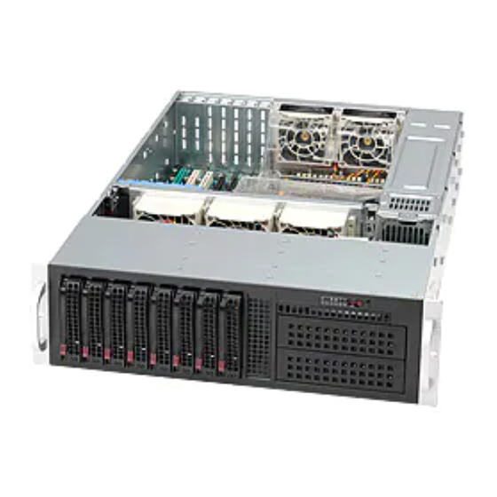
- Page 1 UPER ® SC835 Chassis Series SC835TQ - R800B SC835TQ - R920B USER’S MANUAL 1.0c...
- Page 2 SC835 Chassis Manual The information in this User’s Manual has been carefully reviewed and is believed to be accurate. The vendor assumes no responsibility for any inaccuracies that may be contained in this document, makes no commitment to update or to keep current the information in this manual, or to notify any person or organization of the updates.
- Page 3 Preface Preface About This Manual This manual is written for professional system integrators and PC technicians. It provides information for the installation and use of the SC835 3U chassis. Installa- tion and maintenance should be performed by experienced technicians only. Supermicro’s SC835 3U chassis features a unique and highly-optimized design for dual-core Xeon platforms.
- Page 4 SC835 Chassis Manual Manual Organization Chapter 1: Introduction The first chapter provides a checklist of the main components included with this chassis and contact information. Chapter 2: Warning Statements for AC Systems This chapter lists warnings, precautions, and system safety. You should thoroughly familiarize yourself with this chapter for a general overview of safety precautions that should be followed before installing and servicing this chassis.
-
Page 5: Table Of Contents
Preface Contents Chapter 1 Introduction Overview ......................1-1 Shipping List ....................1-1 Part Numbers ....................1-1 Contacting Supermicro ..................1-2 Returning Merchandise for Service..............1-3 Chapter 2 Standardized Warning Statements for AC Systems About Standardized Warning Statements ............2-1 Warning Definition ................... 2-1 Installation Instructions .................. - Page 6 SC835 Chassis Manual Chapter 4 System Interface Overview ......................4-1 Control Panel Buttons ..................4-2 Control Panel LEDs ..................4-3 Drive Carrier LEDs ..................4-4 Chapter 5 Chassis Setup and Maintenance Overview ......................5-1 Removing the Power Cord ................5-1 Removing the Chassis Cover .................
- Page 7 Preface Rack Mounting Instructions ................6-4 Identifying the Sections of the Rack Rails ............6-4 Locking Tabs ....................6-5 Releasing the Inner Rail ................. 6-5 Installing The Inner Rails on the Chassis ............6-6 Installing the Outer Rails on the Rack ............6-7 Standard Chassis Installation .................
- Page 8 SC835 Chassis Manual Notes viii...
-
Page 9: Chapter 1 Introduction
Please visit the following link for the latest shipping lists and part numbers for your particular chassis model: http://www.supermicro.com/products/chassis/3U/?chs=835 SC835 Chassis Series Power Model I/O Slots Supply 8x 3.5" SAS / SATA 800W SC835TQ-R800B hot swappable drive 7x FF Redundant trays 8x 3.5" SAS / SATA 920W Redundant SC835TQ-R920B hot swappable drive 7x FF... -
Page 10: Contacting Supermicro
SC835 Chassis Manual Contacting Supermicro Headquarters Address: Super Micro Computer, Inc. 980 Rock Ave. San Jose, CA 95131 U.S.A. Tel: +1 (408) 503-8000 Fax: +1 (408) 503-8008 Email: marketing@supermicro.com (General Information) support@supermicro.com (Technical Support) Web Site: www.supermicro.com Europe Address: Super Micro Computer B.V. Het Sterrenbeeld 28, 5215 ML 's-Hertogenbosch, The Netherlands Tel:... -
Page 11: Returning Merchandise For Service
Chapter 1: Introduction Returning Merchandise for Service A receipt or copy of your invoice marked with the date of purchase is required be- fore any warranty service will be rendered. You can obtain service by calling your vendor for a Returned Merchandise Authorization (RMA) number. When returning to the manufacturer, the RMA number should be prominently displayed on the outside of the shipping carton, and mailed prepaid or hand-carried. - Page 12 SC835 Chassis Manual Notes...
-
Page 13: Chapter 2 Standardized Warning Statements For Ac Systems
Chapter 2: Warning Statements for AC Systems Chapter 2 Standardized Warning Statements for AC Systems About Standardized Warning Statements The following statements are industry standard warnings, provided to warn the user of situations which have the potential for bodily injury. Should you have questions or experience difficulty, contact Supermicro's Technical Support department for assistance. - Page 14 SC835 Chassis Manual Warnung WICHTIGE SICHERHEITSHINWEISE Dieses Warnsymbol bedeutet Gefahr. Sie befinden sich in einer Situation, die zu Verletzungen führen kann. Machen Sie sich vor der Arbeit mit Geräten mit den Gefahren elektrischer Schaltungen und den üblichen Verfahren zur Vorbeugung vor Unfällen vertraut.
- Page 15 Chapter 2: Warning Statements for AC Systems جسذٌة اصابة ًتتسبب ف حالة ٌوكي أى ًاًك ف خطز ًٌٌع هذا الزهز !تحذٌز الذوائز بالوخاطز الٌاجوة عي ي على علن ، ك هعذات تعول على أي قبل أى الكهزبائٍة حىادث أي وقىع وٌع...
-
Page 16: Installation Instructions
SC835 Chassis Manual Installation Instructions Warning! Read the installation instructions before connecting the system to the power source. 設置手順書 システムを電源に接続する前に、 設置手順書をお読み下さい。 警告 将此系统连接电源前,请先阅读安装说明。 警告 將系統與電源連接前,請先閱讀安裝說明。 Warnung Vor dem Anschließen des Systems an die Stromquelle die Installationsanweisungen lesen. ¡Advertencia! Lea las instrucciones de instalación antes de conectar el sistema a la red de alimentación. -
Page 17: Circuit Breaker
Chapter 2: Warning Statements for AC Systems Circuit Breaker Warning! This product relies on the building's installation for short-circuit (overcurrent) protection. Ensure that the protective device is rated not greater than: 250 V, 20 A. サーキッ ト ・ ブレーカー この製品は、 短絡 (過電流) 保護装置がある建物での設置を前提としています。 保護装置の定格が250 V、... -
Page 18: Power Disconnection Warning
SC835 Chassis Manual 경고! 이 제품은 전원의 단락(과전류)방지에 대해서 전적으로 건물의 관련 설비에 의존합니다. 보호장치의 정격이 반드시 250V(볼트), 20A(암페어)를 초과하지 않도록 해야 합니다. Waarschuwing Dit product is afhankelijk van de kortsluitbeveiliging (overspanning) van uw electrische installatie. Controleer of het beveiligde aparaat niet groter gedimensioneerd is dan 220V, 20A. - Page 19 Chapter 2: Warning Statements for AC Systems ¡Advertencia! El sistema debe ser disconnected de todas las fuentes de energía y del cable eléctrico quitado de los módulos de fuente de alimentación antes de tener acceso el interior del chasis para instalar o para quitar componentes de sistema. Attention Le système doit être débranché...
-
Page 20: Equipment Installation
SC835 Chassis Manual Equipment Installation Warning! Only trained and qualified personnel should be allowed to install, replace, or service this equipment. 機器の設置 トレーニングを受け認定された人だけがこの装置の設置、 交換、 またはサービスを許可 されています。 警告 只有经过培训且具有资格的人员才能进行此设备的安装、更换和维修。 警告 只有經過受訓且具資格人員才可安裝、更換與維修此設備。 Warnung Das Installieren, Ersetzen oder Bedienen dieser Ausrüstung sollte nur geschultem, qualifiziertem Personal gestattet werden. -
Page 21: Restricted Area
Chapter 2: Warning Statements for AC Systems Waarschuwing Deze apparatuur mag alleen worden geïnstalleerd, vervangen of hersteld door geschoold en gekwalificeerd personeel. Restricted Area Warning! This unit is intended for installation in restricted access areas. A restricted access area can be accessed only through the use of a special tool, lock and key, or other means of security. -
Page 22: Battery Handling
SC835 Chassis Manual אזור עם גישה מוגבלת !אזהרה יש להתקין את היחידה באזורים שיש בהם הגבלת גישה. הגישה ניתנת בעזרת .)'כלי אבטחה בלבד (מפתח, מנעול וכד محظورة مناطق ٍنتركُبها ف هذه انىحذة تخصيص تم ،أداة خاصت من خالل استخذاو فقط محظورة... - Page 23 Chapter 2: Warning Statements for AC Systems Warnung Bei Einsetzen einer falschen Batterie besteht Explosionsgefahr. Ersetzen Sie die Batterie nur durch den gleichen oder vom Hersteller empfohlenen Batterietyp. Entsorgen Sie die benutzten Batterien nach den Anweisungen des Herstellers. Attention Danger d'explosion si la pile n'est pas remplacée correctement. Ne la remplacer que par une pile de type semblable ou équivalent, recommandée par le fabricant.
-
Page 24: Redundant Power Supplies
SC835 Chassis Manual Redundant Power Supplies Warning! This unit might have more than one power supply connection. All connections must be removed to de-energize the unit. 冗長電源装置 このユニッ トは複数の電源装置が接続されている場合があります。 ユニッ トの電源を切るためには、 すべての接続を取り外さなければなりません。 警告 此部件连接的电源可能不止一个,必须将所有电源断开才能停止给该部件供电。 警告 此裝置連接的電源可能不只一個,必須切斷所有電源才能停止對該裝置的供電。 Warnung Dieses Gerät kann mehr als eine Stromzufuhr haben. Um sicherzustellen, dass der Einheit kein trom zugeführt wird, müssen alle Verbindungen entfernt werden. -
Page 25: Backplane Voltage
Chapter 2: Warning Statements for AC Systems امداد الطاقة بوحدات عدة اتصاالت جهاز ال يكون لهذا قد الكهرباء عن وحدة ال لعسل كافة االتصاالت يجب إزالة 경고! 이 장치에는 한 개 이상의 전원 공급 단자가 연결되어 있을 수 있습니다. 이 장치에 전원을... -
Page 26: Comply With Local And National Electrical Codes
SC835 Chassis Manual מתח בפנל האחורי !הרה אז קיימת סכנת מתח בפנל האחורי בזמן תפעול המערכת. יש להיזהר במהלך .העבודה اللىحة أوالطاقة المىجىدة على التيار الكهزبائي مه خطز هناك هذا الجهاس خدمة كه حذرا عند يعمل النظام عندما يكىن 경고! 시스템이... -
Page 27: Product Disposal
Chapter 2: Warning Statements for AC Systems Attention L'équipement doit être installé conformément aux normes électriques nationales et locales. תיאום חוקי החשמל הארצי !אזהרה הציוד חייבת להיות תואמת לחוקי החשמל המקומיים והארציים התקנת المتعلقة المحلية والىطىية قىاويه يجب أن يمتثل لل الكهربائية... -
Page 28: Hot Swap Fan Warning
SC835 Chassis Manual ¡Advertencia! Al deshacerse por completo de este producto debe seguir todas las leyes y reglamentos nacionales. Attention La mise au rebut ou le recyclage de ce produit sont généralement soumis à des lois et/ou directives de respect de l'environnement. Renseignez-vous auprès de l'organisme compétent. - Page 29 Chapter 2: Warning Statements for AC Systems 警告 當您從機架移除風扇裝置,風扇可能仍在轉動。小心不要將手指、螺絲起子和其他 物品太靠近風扇。 Warnung Die Lüfter drehen sich u. U. noch, wenn die Lüfterbaugruppe aus dem Chassis genommen wird. Halten Sie Finger, Schraubendreher und andere Gegenstände von den Öffnungen des Lüftergehäuses entfernt. ¡Advertencia! Los ventiladores podran dar vuelta cuando usted quite ell montaje del ventilador del chasis.
-
Page 30: Power Cable And Ac Adapter
SC835 Chassis Manual Power Cable and AC Adapter Warning! When installing the product, use the provided or designated connection cables, power cables and AC adaptors. Using any other cables and adaptors could cause a malfunction or a fire. Electrical Appliance and Material Safety Law prohibits the use of UL or CSA -certified cables (that have UL/CSA shown on the code) for any other electrical devices than products designated by Supermicro only. - Page 31 Chapter 2: Warning Statements for AC Systems Attention Lors de l'installation du produit, utilisez les bables de connection fournis ou désigné. L'utilisation d'autres cables et adaptateurs peut provoquer un dysfonctionnement ou un incendie. Appareils électroménagers et de loi sur la sécurité Matériel interdit l'utilisation de UL ou CSA câbles certifiés qui ont UL ou CSA indiqué...
- Page 32 SC835 Chassis Manual Notes 2-20...
-
Page 33: Chapter 3 Chassis Components
Chapter 3: Chassis Components Chapter 3 Chassis Components This chapter describes some common components included with your chassis. For the latest information and shipping lists, visit: http://www.supermicro.com. Components Drive Bays The SC835 chassis supports all of the below: • Eight 3.5" SAS/SATA hot-swap hard drives. SAS or enterprise SATA are recom- mended. -
Page 34: Fans
SC835 Chassis Manual Fans The chassis accepts three 8cm hot-swappable central fans and two 8cm rear exhaust fan. These fans are powered by 3-pin connectors from the motherboard. . Air Shroud Air shrouds funnel air directly to where it is needed for cooling. Always use the air shroud included with your chassis. -
Page 35: Chapter 4 System Interface
Chapter 4: System Interface Chapter 4 System Interface Overview There are several LEDs on the control panel and others on the drive carriers to keep you informed of the overall status of the system and the activity and health of specific components. The chassis control panel includes a reset button and an on/off switch. -
Page 36: Control Panel Buttons
SC835 Chassis Manual Control Panel Buttons There are two push-buttons located on the front of the chassis. • Power: The main power switch is used to apply or remove power from the power supply to the server system. Turning off system power with this button removes the main power but keeps standby power supplied to the system. -
Page 37: Control Panel Leds
Chapter 4: System Interface Control Panel LEDs • The control panel on the front of the chassis has six status LEDs. • Power Failure: When this LED flashes, it indicates a power failure in the power supply. • Alert: This LED is illuminated when an alert condition occurs. Informational LED Status Description... -
Page 38: Drive Carrier Leds
SC835 Chassis Manual • HDD: Indicates IDE channel activity. SAS/SATA drive and/or DVD-ROM drive activity when flashing. • Power: Indicates power is being supplied to the system's power supply units. This LED should normally be illuminated when the system is operating. Drive Carrier LEDs Each SAS drive carrier has two LEDs on the front of the carrier. -
Page 39: Chapter 5 Chassis Setup And Maintenance
Chapter 5: Chassis Setup Chapter 5 Chassis Setup and Maintenance Overview This chapter covers the steps required to install components and perform mainte- nance on the chassis. The only tool required is a Phillips screwdriver. Review the warnings and precautions listed in the manual before setting up or servicing this chassis. -
Page 40: Removing The Chassis Cover
SC835 Chassis Manual Removing the Chassis Cover Release Tab Cover Screw Figure 5-1. Removing the Chassis Cover Removing the Chassis Cover 1. Press the release tabs to release the cover from the locked position. Press both tabs at the same time. It may also be necessary to remove the chassis cover screw. -
Page 41: Installing Drives
Chapter 5: Chassis Setup Installing Drives Each SC835 chassis provides carriers for eight 3.5" hard disk drives. There is also one optional slim DVD drive plus two 5.25" full height drive bays that can house additional hard disk drives or removable media drives. Installing 3.5"... - Page 42 SC835 Chassis Manual Installing a Hard Drive into the Drive Carrier 1. Remove the two screws securing the dummy drive to the drive carrier. 2. Lift the dummy drive out of the drive carrier. Drive Carrier Release Button Figure 5-3. Removing the Dummy Drive from the Carrier Note: Only enterprise level hard disk drives are recommended.
- Page 43 Chapter 5: Chassis Setup SAS/SATA Hard Drive Drive Carrier Use a hard, stable surface when installing the hard drive. Figure 5-4. Installing a Drive into a Hard Drive Carrier 3. Place the hard drive carrier on a flat, stable surface such as a desk or work bench.
-
Page 44: Installing The Slim Dvd Drive
SC835 Chassis Manual Installing the Slim DVD Drive The chassis supports a slim DVD drive just under the control panel. 1. Power down the system as described in Section 5-2. and remove the cover. 2. If a new front port panel is not being installed, remove the mini-bezel from the drive bay The mini-bezel is the small grating that covers the drive bay. -
Page 45: Installing The Motherboard
Chapter 5: Chassis Setup Installing the Motherboard Permanent and Optional Standoffs Standoffs prevent short circuits by securing space between the motherboard and the chassis surface. The SC835 chassis includes permanent standoffs in locations used by most motherboards. These standoffs accept the rounded Phillips head screws included in the accessories packaging. -
Page 46: Motherboard Installation Procedure
SC835 Chassis Manual Motherboard Installation Procedure Figure 5-6. Installing the Motherboard Installing the Motherboard 1. Review the documentation that came with your motherboard. Become familiar with component placement, requirements, and precautions. 2. Open the chassis cover. 3. Remove any packaging from the chassis. If the rear fan or the air shroud is in place, remove them. -
Page 47: Installing Expansion Cards
Chapter 5: Chassis Setup Installing Expansion Cards The chassis includes space for up to seven expansion cards. I/O Port Panel Expansion Card Slots Figure 5-7. Expansion Card Slots and I/O Ports Installing Expansion Cards 1. Remove the chassis cover. 2. Locate the motherboard port aligned with the card slot you want to install. 3. -
Page 48: Installing Cooling Elements
SC835 Chassis Manual Installing Cooling Elements Figure 5-8. Installing the Air Shroud Air shrouds concentrate airflow to maximize fan efficiency. The SC835 chassis air shroud does not require screws to set it up. Note that the rear fans must be removed prior to installing the air shroud. -
Page 49: System Fans
Chapter 5: Chassis Setup System Fans Five heavy-duty fans provide cooling for the chassis, three front fans and two rear fans. The fans are fully hot-swappable, that is they may be removed and replaced without having to power-down the server. Fan Release Tab Fan Release Tab Front Fan (3 total) -
Page 50: Rear System Fans
SC835 Chassis Manual Rear System Fans The standard rear fans must be installed after motherboard and air shroud setup. Figure 5-10. Installing the Rear Fan Installing the Rear System Fans Installing a the Rear System Fans 1. Confirm that the air shroud is correctly placed. 2. -
Page 51: Checking The Server Air Flow
Chapter 5: Chassis Setup Checking the Server Air Flow Checking the Air Flow 1. Make sure there are no objects to obstruct airflow in and out of the server. If necessary, route the cables through the cable rack. 2. Do not operate the chassis without drives or drive trays in the drive bays. 3. -
Page 52: Power Supply
SC835 Chassis Manual Power Supply The power supply is redundant and hot-swappable, meaning that the power supply can be changed without powering down the system. Replacing the Power Supply Replacing the Power Supply 1. The server may continue running if only one power supply module is removed at a time. -
Page 53: Replacing The Power Distributor
Chapter 5: Chassis Setup Replacing the Power Distributor The power distributor provides failover and redundancy. In the unlikely event the power distributor must be replaced, follow this procedure. Installing the Power Distributor 1. Power down the system as described in Section 5-2 and remove the cover. 2. - Page 54 SC835 Chassis Manual Notes 5-16...
-
Page 55: Chapter 6 Rack Installation
Chapter 6: Rack Installation Chapter 6 Rack Installation This chapter provides instructions and tips for installing the chassis into a rack. Preparing for Setup Please read this section in its entirety before beginning the installation procedure. Choosing a Setup Location Decide on a suitable location for the rack. -
Page 56: Circuit Overloading
SC835 Chassis Manual Circuit Overloading Avoid overloading the power supply circuitry or any overcurrent protection equip- ment. Use equipment nameplate ratings to calculate your requirements. Reliable Ground A reliable ground must be maintained at all times. To ensure this, ground the rack, itself. - Page 57 Chapter 6: Rack Installation • Allow the hard drives and power supply modules to cool before touching them. • Always keep the rack front door, all panels and all components on the servers closed when not servicing, to maintain proper cooling. Warning: Do not pick up the server by the front handles.
-
Page 58: Rack Mounting Instructions
SC835 Chassis Manual Rack Mounting Instructions This section provides information on installing the chassis into a rack unit with the rails provided. There are a variety of rack units on the market, which may mean that the assembly procedure will differ slightly from the instructions provided. You should also refer to the installation instructions that came with the rack unit you are using. -
Page 59: Locking Tabs
Chapter 6: Rack Installation Locking Tabs Each inner rail has a locking tab. This tab locks the chassis into place when installed and pushed fully into the rack. These tabs also lock the chassis in place when fully extended from the rack. This prevents the server from coming completely out of the rack when when the chassis is pulled out for servicing. -
Page 60: Installing The Inner Rails On The Chassis
SC835 Chassis Manual Figure 6-3. Installing the Inner Rail Extensions Installing The Inner Rails on the Chassis Installing the Inner Rails 1. Confirm that the left and right inner rails have been correctly identified. Place the inner rail firmly against the side of the chassis, aligning the hooks on the side of the chassis with the holes in the inner rail. -
Page 61: Installing The Outer Rails On The Rack
Chapter 6: Rack Installation SCREW screw the handles t outer rails for secur purpose if necessar Figure 6-4. Assembling the Outer Rails Installing the Outer Rails on the Rack Installing the Outer Rails 1. Press upward on the locking tab at the rear end of the middle rail. 2. -
Page 62: Standard Chassis Installation
SC835 Chassis Manual SCREW Figure 6-5. Installing the Chassis into a Rack Stability hazard. The rack stabilizing mechanism must be in place, or the rack must be bolted to the floor before you slide the unit out for servicing. Failure to stabilize the rack can cause the rack to tip over. Standard Chassis Installation Installing the Chassis into a Rack 1. -
Page 63: Appendix A Sc835 Chassis Cables
This appendix lists supported cables for your chassis system. It only includes the most commonly used components and configurations. For more compatible cables, refer to the manufacturer of the motherboard you are using and our Web site at: www.supermicro.com. A-2 Cables Included with SC835TQ Chassis (SAS/SATA) SC835TQ-R800B Part # Type... - Page 64 SC835 Chassis Manual A-3 Compatible Cables This section lists cables included with the SC835 Chassis packages. Alternate SAS Cables Some compatible motherboards have different connectors. If your motherboard has only one SAS connector that the SAS cables must share, use one of the following cables.
- Page 65 Appendix A: Chassis Cables Cascading/JBOD SAS Cables Use the following cables when setting up a cascading or JBOD system. Cable Name: SAS Cable Quantity: varies by setup Part #: CBL-0167L Placement: Internal cable Ports: Single Description: Internal cable. Connects the backplane to the Host Bus Adapter (HBA) or external port.
- Page 66 SC835 Chassis Manual Cable Name: SAS Cable Quantity: varies by setup Part #: CBL-0166L Placement: External cable Ports: Single or Dual Description: External cascading cable. Connects ports between servers. With most connectors, use one cable for single port connections and two cables for dual port connections.
- Page 67 Appendix A: Chassis Cables Extending Power Cables Although Supermicro chassis are designed with to be efficient and cost-effective, some compatible motherboards have power connectors located in different areas. To use these motherboards you may have to extend the power cables to the mother boards.
- Page 68 SC835 Chassis Manual Notes...
-
Page 69: Appendix B Power Supply Specifications
Appendix B: Power Supply Appendix B Power Supply Specifications This appendix lists power supply specifications for your chassis system. SC835TQ-R800B 800W (Redundant) MFR Part # PWS-801-1R 100 - 240V Rated AC Voltage 50 - 60Hz 10A - 4 Amp +5V standby 4 Amp... - Page 70 SC835 Chassis Manual Power Supply Connections Connect each of the following cables, as required, by your motherboard manufac- turer. In some instances, some cables may not need to be connected. Power Supply Cables Name Number Connects to: Description 20-pin or 24-pin power cable pro- vides electricity to the motherboard.
-
Page 71: Appendix C Sas-833Tq Backplane Specifications
Appendix C: SAS-833TQ Backplane Specifications Appendix C SAS-833TQ Backplane Specifications To avoid personal injury and property damage, carefully follow all the safety steps listed below when accessing your system or handling the components. C-1 ESD Safety Guidelines Electrostatic Discharge (ESD) can damage electronic com ponents. To prevent dam- age to your system, it is important to handle it very carefully. -
Page 72: C-3 An Important Note To Users
SC835 Chassis Manual C-3 An Important Note to Users • All images and layouts shown in this user's guide are based upon the latest PCB Revision available at the time of publishing. The card you have received may or may not look exactly the same as the graphics shown in this manual. C-4 Introduction to the SAS-833TQ Backplane The SAS-833TQ backplane has been designed to utilize the most up-to-date tech- nology available, providing your system with reliable, high-quality performance. -
Page 73: C-5 Front Connectors And Jumpers
Appendix C: SAS-833TQ Backplane Specifications Jumper Settings and Pin Definitions C-5 Front Connectors and Jumpers Buzzer Figure C-1: Front Components Front Components Front Jumpers and Components: 1. Upgrade Connector JP69 2. I C Connector#1 JP37 and I C Connector#2 JP95 3. - Page 74 SC835 Chassis Manual 10. SAS Port #2 J7 11. SAS Port #3 J8 12. SAS Port #4 J10 13. SAS Port #5 J12 14. SAS Port #6 J14 15. SAS Port #7 J16...
-
Page 75: C-6 Front Connector And Pin Definitions
Appendix C: SAS-833TQ Backplane Specifications C-6 Front Connector and Pin Definitions 1. Upgrade Connector The upgrade connector, designated JP69, is used for manufacturer's diagnostic purposes only. 2. I C Connectors C Connector Pin Definitions The I C connectors, designated JP37 and Pin# Definition JP95, are used to monitor HDD activity and Data... - Page 76 SC835 Chassis Manual 5. Backplane Main Power Connectors Backplane Main Power The 4-pin connectors, designated JP10 and 4-Pin Connector JP13 provide power to the backplane. See Pin# Definition the table on the right for pin definitions. +12V 2 and 3 Ground 6.
-
Page 77: C-7 Front Jumper Locations And Pin Definitions
Appendix C: SAS-833TQ Backplane Specifications C-7 Front Jumper Locations and Pin Definitions JP35 JP84 JP97 JP99 JP98 JP61 JP62 JP63 Figure C-2: Jumper Locations Explanation of Jumpers Connector To modify the operation of the backplane, Pins jumpers can be used to choose between optional settings. -
Page 78: Fan Jumper Settings
SC835 Chassis Manual Jumper Settings Jumper Jumper Settings Note 1-2: Reset JP35 MG9072 chip reset 2-3: No reset Socket Settings Socket Socket Setting Note Buzzer reset* JP18 Connected to front panel Press once to disable buzzer Press twice to enable buzzer *The buzzer sound indicates that a condition requiring immediate attention has occurred. -
Page 79: I 2 C And Sgpio Modes And Jumper Settings
Appendix C: SAS-833TQ Backplane Specifications C and SGPIO Modes and Jumper Settings This backplane can utilize I C or SGPIO. SGPIO is the default mode and can be used without making changes to your jumpers. The following information details which jumpers must be configured to use I C mode or restore your backplane to SGPIO mode. -
Page 80: Front Led Indicators
SC835 Chassis Manual Front LED Indicators +5V LED FAN FAIL +12V LED #1 #2 #3 LEDs ALARM Figure C-3: Front LEDs Front Panel LEDs Normal State Specification Fan #1 fail Failure in Fan #1 Fan #2 fail Failure in Fan #2 Fan #3 fail Failure in Fan #3 Alarm #1... -
Page 81: C-8 Rear Connectors And Led Indicators
Appendix C: SAS-833TQ Backplane Specifications C-8 Rear Connectors and LED Indicators SAS #0 SAS #1 SAS #2 SAS #3 SAS #4 SAS #5 SAS #6 SAS #7 Figure C-4: Rear Connectors Rear SAS/SATA Connectors Rear SAS/SATA Drive Connector Number SAS #0 SAS/SATA HDD #0 SAS #1 SAS/SATA HDD #1... - Page 82 SC835 Chassis Manual Disclaimer (cont.) The products sold by Supermicro are not intended for and will not be used in life sup- port systems, medical equipment, nuclear facilities or systems, aircraft, aircraft devices, aircraft/emergency communication devices or other critical systems whose failure to per- form be reasonably expected to result in significant injury or loss of life or catastrophic property damage.
Need help?
Do you have a question about the SC835TQ and is the answer not in the manual?
Questions and answers