
Subscribe to Our Youtube Channel
Related Manuals for Keysight Technologies 66312A


Summary of Contents for Keysight Technologies 66312A
- Page 1 Keysight Model 66312A Dynamic Measurement DC Source System Keysight Models 6611C, 6612C, 6613C, and 6614C DC Power Supplies User’s Guide...
-
Page 3: Warranty Information
Warranty Information CERTIFICATION Keysight Technologies certifies that this product met its published specifications at time of shipment from the factory. Keysight Technologies further certifies that its calibration measurements are traceable to the United States National Bureau of Standards, to the extent allowed by the Bureau's calibration facility, and to the calibration facilities of other International Standards Organization members. -
Page 4: Safety Summary
Failure to comply with these precautions or with specific warnings elsewhere in this manual violates safety standards of design, manufacture, and intended use of the instrument. Keysight Technologies assumes no liability for the customer's failure to comply with these requirements. - Page 5 SAFETY SYMBOLS Direct current Alternating current Both direct and alternating current Three-phase alternating current Earth (ground) terminal Protective earth (ground) terminal Frame or chassis terminal Terminal is at earth potential. Used for measurement and control circuits designed to be operated with one terminal at earth potential.
- Page 6 Declares under sole responsibility that the product as originally delivered a) Mobile Communications DC Source Product Names b) System DC Power Supply Model Numbers a) 66332A, 66312A, 66311B, 66311D 66309B, 66309D, 66319B, 66319D, 66321B, 66321D b) 6631B, 6632B, 6633B, 6634B 6611C 6612C, 6613C, 6614C Product Options This declaration covers all options and customized products based on the above products.
-
Page 7: Acoustic Noise Information
This document contains proprietary information protected by copyright. All rights are reserved. No part of this document may be photocopied, reproduced, or translated into another language without the prior consent of Keysight Technologies. The information contained in this document is subject to change without notice. -
Page 8: Table Of Contents
Declaration Page Acoustic Noise Information Printing History Table of Contents 1 - QUICK REFERENCE Keysight 66312A Dynamic Measurement DC Source and Keysight 6611C/6612C/6613C/6614C System DC Power Supply The Front Panel - At a Glance Front Panel Number Entry Front Panel Annunciators... - Page 9 4 - TURN-ON CHECKOUT Introduction Using the Keypad Checkout Procedure In Case of Trouble Error Messages Line Fuse 5 - FRONT PANEL OPERATION Introduction Front Panel Description System Keys Function Keys Immediate Action Keys Scrolling Keys Metering Keys Output Control Keys Entry Keys Examples of Front Panel Programming 1 - Setting the Output Voltage and Current...
-
Page 10: Quick Reference
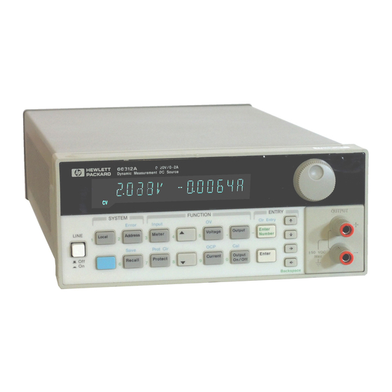
Keysight 6611C/6612C/6613C/6614C System DC Power Supply The Keysight 66312A is a 40 Watt, high performance dc power supply that provides dynamic measurement and analysis of voltage and current waveforms. It is designed to simplify the testing of digital cellular and mobile phones. For example, data acquired using its dynamic measurement capability can be used in determining the battery operating time of digital wireless communications products. -
Page 11: The Front Panel - At A Glance
1 - Quick Reference The Front Panel - At a Glance 14-character display Annunciators Rotary control Front panel output shows output indicate operating sets voltage, current, connectors. measurements and modes and status and menu parameters. programmed values. conditions. -
Page 12: Front Panel Number Entry
Quick Reference - 1 Front Panel Number Entry Enter numbers from the front panel using one of the following methods: Use the arrow keys and knob to change voltage or current settings NOTE The output must be ON to see the displayed values change in Meter mode. Use the Function keys and knob to change the displayed settings Use the arrow keys to edit individual digits in the displayed setting Increments the flashing digit... -
Page 13: Front Panel Annunciators
1 - Quick Reference Front Panel Annunciators The output is operating in constant voltage mode. The output is operating in constant current mode. The output is unregulated. The output is OFF. Press the Output On/Off key to turn the output on. The over-current protection state is ON. -
Page 14: Front Panel Menus - At A Glance
Accesses calibration menu (See User’s Guide). CAL ON Shift to select menu parameters. Meter to exit any menu and return to metering mode. Not available on Keysight 6611C – 6614C or in Compatibility mode. Not available on Keysight 66312A. -
Page 15: Scpi Programming Commands - At A Glance
:VOLTage POS | NEG | EITH :SOURce BUS | INTernal [:SEQuence1 | :TRANsient] [:IMMediate] Not available on Keysight 6611C – 6614C :SOURce BUS Fetch commands not available on Keysight 6611C – :SEQuence1 :DEFine TRANsient 6614C Not available on Keysight 66312A :SEQuence2 :DEFine ACQuire... -
Page 16: The Rear Panel - At A Glance
Quick Reference - 1 The Rear Panel - At a Glance GPIB (IEEE-488) RS-232 interface INH/FLT (remote Output and interface connector connector INHibit / internal Remote sense FauLT) connector. connector. Connector Connector plug is plug is removable. removable. -
Page 18: General Information
General Information Document Orientation This manual describes the operation of the Keysight Model 66312A Dynamic Measurement DC Source and the Keysight Model 6611C, 6612C 6613C and 6614C System DC Power Supplies. Unless otherwise noted, all units will be referred to by the description "dc source" throughout this manual. The following documents and software are shipped with your dc source: ... -
Page 19: Safety Considerations
120 Vac nominal, 50/60 Hz 220 Vac nominal, 50/60 Hz 230 Vac nominal, 50/60 Hz Isolation and polarity reversal relays (not available on Keysight 66312A) Rack mount kit for one unit (p/n 5062-3972) Rack mount kit for 2 side-by-side units. Consists of: Lock-link kit (p/n 5061-9694) and Flange kit (p/n 5062-3974) Rack mount and slide kit for 2 side-by-side units of different depth. -
Page 20: Description
General Information - 2 Description Both the Keysight 66312A Dynamic Measurement DC Source and the Keysight 6611C, 6612C, 6613C and 6614C System DC Power Supplies combine two instruments in one unit. They include a dc source, which produces dc output with programmable voltage and current amplitude, and a highly accurate voltage and current meter, with the capability to measure very low-level currents. -
Page 21: Output Characteristic
2 - General Information Output Characteristic The dc source's output characteristic is shown in the following figure. The output of the dc source may be adjusted to any value within the boundaries shown. Output Voltage CV operating line Vmax VSET CC operating line Output Current... -
Page 22: Installation
Installation Inspection Damage When you receive your dc source, inspect it for any obvious damage that may have occurred during shipment. If there is damage, notify the shipping carrier and the nearest Keysight Sales and Support Office immediately. The list of Keysight Sales and Support Offices is at the back of this guide. Warranty information is printed in the front of this guide. -
Page 23: Location
Installation instructions are included with each rack mount option. NOTE: Support rails or an instrument shelf is required when rack mounting units. 368.3 mm 14.5 (6611C-6614C) 444.4 mm 17.5 (66312A only) 350.5 mm 13.8 (6611C-6614C) 425.8 mm 16.8 (66312A only) Figure 3-1. Outline Diagram... -
Page 24: Input Connections
Installation - 3 Input Connections Connect the Power Cord 1. Unscrew the line fuse cap from the rear panel and verify that the fuse rating matches what is specified on the FUSES label on the rear panel. Reinstall the fuse. (See table 3-1 for part numbers.) 2. -
Page 25: Voltage Drops
3 - Installation Voltage Drops The load wires must also be large enough to avoid excessive voltage drops due to the impedance of the wires. In general, if the wires are heavy enough to carry the maximum short circuit current without overheating, excessive voltage drops will not be a problem. -
Page 26: Remote Sense Connections
Installation - 3 Remote Sense Connections Under normal operation, the dc source senses the output voltage at the output terminals on the back of the unit. External sense terminals are available on the back of the unit that allow the output voltages to be sensed at the load, compensating for impedance losses in the load wiring. -
Page 27: Stability
10,000 F. Keysight 6612C and Keysight 66312A 6614C If your load capacitance approaches this limit, it is recommended that you do not intentionally trip the OVP and discharge the capacitance through the SCR as part of your normal testing procedure, as this may lead to long-term failure of some components. - Page 28 Installation - 3 The connector accepts wires sizes from AWG 22 to AWG 12. Disconnect the mating plug to make your wire connections. NOTE: It is good engineering practice to twist and shield all signal wires to and from the digital connectors.
-
Page 29: Controller Connections
3 - Installation Digital I/O Connections As shown in Table 3-3 and Figure 3-5, the FLT/INH connector can also be configured as a digital I/O port. Information on programming the digital I/O port is found in chapter 5 and under [SOURce:]DIGital:DATA and [SOURce:]DIGital: FUNCtion commands in the Programming Guide. -
Page 30: Rs-232 Interface
The total length of all cables used is no more than 2 meters times the number of devices connected ♦ together, up to a maximum of 20 meters. (Refer to table 2-2 for a list of GPIB cables available from Keysight Technologies.) Do not stack more than three connector blocks together on any GPIB connector. ♦... - Page 32 Turn-On Checkout Introduction Successful tests in this chapter provide a high degree of confidence that the dc source is operating properly. For verification tests, see appendix B. Complete performance tests are given in the Service Guide. NOTE: This chapter provides a preliminary introduction to the dc source front panel. See chapter 5 for more details.
- Page 33 Voltage OV Prot Current Note: 6611C The checkout procedure is written for models 6612C/66312A 6612C and 66312A. If you have another 6613C model, enter the correct values from the table 6614C where the procedure calls for an <input>. Procedure Display Explanation Turn the unit on.
- Page 34 Turn-On Checkout - 4 Procedure Display Explanation Press Enter Number, VOLT:PROT 8 Programs the OVP to 8 volts, which is less than 8, Enter the previously set output voltage. 0.449V 0.145A Because the OVP voltage entered was less than the output voltage, the OVP circuit tripped. The output dropped to zero, CV turned off, and Prot turned on.
- Page 35 4 - Turn-On Checkout In Case of Trouble Error Messages Dc source failure may occur during power-on selftest or during operation. In either case, the display may show an error message that indicates the reason for the failure. Selftest Errors Pressing the Shift, Error keys will show the error number.
- Page 36 Front panel Operation Introduction Here is what you will find in this chapter: a complete description of the front panel controls front panel programming examples NOTE: The dc source must be in set to Local mode to use the front panel controls. Press the key on the front panel to put the unit in local mode.
- Page 37 5 - Front Panel Operation 14-character vacuum fluorescent display for showing output measurements Display and programmed values. Annunciators light to indicate operating modes and status conditions: Annunciators CV The dc source output is in constant-voltage mode. CC The dc source output is in constant-current mode. Unr The dc source output is in an unregulated state.
- Page 38 Front Panel Operation - 5 System Keys Refer to the examples later in this chapter for more details on the use of these keys. SYSTEM Error Local Address Save Recall Figure 5-2. System Keys Shift This is the blue, unlabeled key, which is also shown as in this guide.
- Page 39 5 - Front Panel Operation Function Keys Refer to the examples later in this chapter for more details on the use of these keys. FUNCTION Input Output Meter Voltage Prot Cir Current Output Protect On/Off Figure 5-3. Function Keys Immediate Action Keys Immediate action keys immediately execute their corresponding function when pressed.
- Page 40 Front Panel Operation - 5 Metering Keys Metering keys control the metering functions of the dc source. When the unit is operating in front panel meter mode, all front panel measurements are calculated from a total of 2048 readings taken at a 46.8 microsecond sampling rate.
- Page 41 This key accesses the calibration menu (Refer to Appendix B for details). Notes: These parameters are stored in non-volatile memory These status summary bits are explained in chapter 3 of the Programming Guide Not available on Keysight 66312A value = a numeric value char = a character string parameter ...
- Page 42 Front Panel Operation - 5 Entry Keys Refer to the examples later in this chapter for more details on the use of these keys. ENTRY Cir Entry Enter Number Enter Backspace Figure 5-4. Entry Keys Ë Ì These keys let you scroll through choices in a parameter list that apply to a specific command.
- Page 43 5 - Front Panel Operation Examples of Front Panel Programming You will find these examples on the following pages: Setting the output voltage and current Querying and clearing output protection Making front panel measurements Programming the digital port Programming the output relay (option 760 only) Setting the GPIB address or RS-232 parameters Saving and recalling operating states Similar examples are given in the dc source Programming Guide using SCPI commands.
- Page 44 When controlling the unit over the GPIB interface, you can vary both the sampling rate and the number of data points in each measurement. If you are using the Keysight 66312A dc source to measure waveform data, the GPIB interface also lets you qualify the triggers that initiate the measurements. With this flexibility, measurement accuracy can be improved for waveforms with frequencies as low as several Hertz.
- Page 45 V or A LOW V or A MIN 100 millisecond acquisition time Figure 5-5. Front Panel Pulse Measurement Parameters (Keysight 66312A only) Use the Meter menu for making front panel measurements: Action Display For current measurements, press Shift, Input. Then press until you CURR:RANG AUTO obtain the CURR:RANG AUTO command.
- Page 46 Front Panel Operation - 5 4 - Programming the Digital Output Port Your dc source is shipped with the output port function set to RIDFI mode. In this mode the port functions as a remote inhibit input with a discrete fault indicator output signal. You can also configure the port to act as a Digital Input/Output device.
- Page 47 5 - Programming the Output Relay (option 760 only) Units with option 760 have isolation and polarity reversal relays connected to the output and sense terminals. (Option 760 is not available on Keysight 66312A units.) To control the relays independently of the Output On/Off switch, proceed as follows:...
- Page 48 Front Panel Operation - 5 7 - Saving and Recalling Operating States NOTE: This capability is only available when the unit is set to the SCPI programming language. You can save up to 4 states (from location 0 to location 3) in non-volatile memory and recall them from the front panel.
- Page 50 Applies for output voltages greater than 10mV (Keysight 6611C/12C), 25mV (Keysight 6613C), and 50mV (Keysight 6614C). For Keysight 66312A: applies in SCPI mode, with current detector set to DC. With current detector set to ACDC, accuracy is 0.2% + four times the fixed error value.
- Page 51 Table A-2. Supplemental Characteristics Parameter Keysight 6611C Keysight6612C Keysight 6613C Keysight 6614C Keysight 66312A Input Rating 100 Vac mains: 100 Vac nominal, 50/60 Hz, 2A, 200 VA max. (at full load ) 120 Vac mains: 120 Vac nominal, 50/60 Hz, 1.7A, 200 VA max.
- Page 52 Specifications - A Table A-2. Supplemental Characteristics (continued) Parameter Keysight 66312A Keysight 6611C - 6614C Instantaneous Voltage: 0.03% + 5 mV not applicable Dynamic Measurement Accuracy Instantaneous Current: 0.6% + 1 mA Dynamic Measurement Buffer Length: 4096 points not applicable...
- Page 53 A - Specifications Table A-2. Supplemental Characteristics (continued) Parameter Keysight 66312A Keysight 6611C - 6614C Digital IN Port 2: Low-level input current @ 0.4 V = 1.25 mA Digital I/O Characteristics (continued) (internal pull-up) High-level input current @ 5 V = 0.25 mA Low-level input voltage = 0.8 V max.
- Page 54 Verification and Calibration Introduction This appendix includes verification and calibration procedures for the Keysight 66312A, 6611C, 6612C, 6613C and 6614C dc source. Instructions are given for performing the procedures either from the front panel or from a controller over the GPIB.
- Page 55 Load Voltmeter Ammeter Resistor monitor SENSE Local Calibration Load Resistor Remote NOTE: Connector 6611C is removable 1.1K 6612C & 66312A 2.5 K 6613C 50VDC MAX TO 6614C Set to Remote Load Ammeter resistor 400 ohm External DC supply Figure B-1. Verification & Calibration Test Setup...
- Page 56 Table B-2. Verification Programming Values Full scale Full Scale Imax Isink Voltage Current 6611C 5.1188 - 3 A 6612C/66312A 2.0475 - 1.2 A 6613C 1.0238 - 0.6 A 6614C 0.5118 - 0.3 A Turn-On Checkout Perform the Turn-On Checkout as directed in chapter 4.
- Page 57 B - Verification and Calibration Divide the voltage drop across the current monitor by its resistance Readings within low current to convert the value to amperes. Record the value. limits (see table B-3, 4, 5 or 6). Set the output current to full scale (see table B-2).. Divide the voltage drop across the current monitor by its resistance Readings within high current to convert the value to amperes.
- Page 58 Low Current Sink measurement _____A sink sink 11.1 mA High Current Sink measurement _____mA +11.1 mA sink sink Table B-4. Verification Test Record for Keysight 66312A or Keysight 6612C Model Keysight______________________ Report No.____________ Date_____________ Test Description Minimum Recorded Results Maximum Specification Specification Voltage Programming and Measurement 10 mV...
- Page 59 B - Verification and Calibration Table B-5. Verification Test Record for Keysight 6613C Model Keysight 6613C Report No.____________ Date_____________ Test Description Minimum Recorded Results Maximum Specification Specification Voltage Programming and Measurement 20 mV Low Voltage V _______V +20 mV 6 mV Front Panel measurement _____mV +6 mV...
- Page 60 Verification and Calibration - B Performing the Calibration Procedure NOTE: The calibration procedure can only be performed using the SCPI language commands. Use either the front panel key to access the LANG command, or use the Address SYSTem:LANGuage command to change the programming language to SCPI. Table B-1 lists the equipment required for calibration.
- Page 61 B - Verification and Calibration Front Panel Calibration These procedures assume you understand how to operate front panel keys (see chapter 5). Enable Calibration Mode Action Display Reset the unit by selecting Output, scrolling to *RST and pressing *RST Enter. Press Output On/Off to enable the output.
- Page 62 Press Shift Cal and scroll to CAL DATA. Wait for the DMM CAL:DATA 0.00 reading to stabilize. Then press Enter Number and enter the current reading displayed on the DMM. AC Current Measurement Calibration (Keysight 66312A only) Action Display Disconnect all loads from the dc source.
- Page 63 B - Verification and Calibration Saving the Calibration Constants WARNING: Storing calibration constants overwrites the existing ones in non-volatile memory. If you are not sure you want to permanently store the new constants, omit this step. The dc source calibration will then remain unchanged. Action Display Press Shift Cal, scroll to CAL SAVE, and press Enter.
- Page 64 Verification and Calibration - B Calibration Over the GPIB You can calibrate the dc source by using SCPI commands within your controller programming statements. Be sure you are familiar with calibration from the front panel before you calibrate from a controller.
- Page 66 Error Messages Error Number List This appendix gives the error numbers and descriptions that are returned by the dc source. Error numbers are returned in two ways: Error numbers are displayed on the front panel Error numbers and messages are read back with the SYSTem:ERRor? query. SYSTem:ERRor? returns the error number into a variable and returns two parameters: an NR1 and a string.
- Page 67 C - Error Messages –138 Suffix not allowed –141 Invalid character data [bad character, or unrecognized] –144 Character data too long –148 Character data not allowed –150 String data error –151 Invalid string data [e.g., END received before close quote] –158 String data not allowed –160...
- Page 68 Error Messages - C Selftest Errors 0 through 99 (sets Standard Event Status Register bit #3) No error Non-volatile RAM RD0 section checksum failed Non-volatile RAM CONFIG section checksum failed Non-volatile RAM CAL section checksum failed Non-volatile RAM STATE section checksum failed Non-volatile RST section checksum failed RAM selftest VDAC/IDAC selftest 1...
- Page 70 Line Voltage Conversion WARNING: Shock Hazard Operating personnel must not remove instrument covers. Component replacement and internal adjustments must be made only by qualified service personnel. Open the Unit Turn off ac power and disconnect the power cord from the unit. ...
- Page 71 D - Line Voltage Conversion Install the Correct Line Fuse Unscrew the line fuse cap from the rear panel and install the correct fuse. For 100/120 Vac operation: 2.5 AT (time delay); part number 2110-0633 For 220/230 Vac operation: 1.25 AT (time delay); part number 2110-0788 ...
- Page 72 Index checkout procedure, 32 — — cleaning, 21 clear protection, 43 controller connections, 28 -- -- -- -- -- --, 43 controls and indicators, 19 conversion, ac line, 69 —+— crowbar circuit, 26 current measurement range, 43 +/- terminals, 23 CV mode, 20, 42 +S/-S terminals, 23 —D—...
- Page 73 Index OCP, 38 operating features, 19 Output, 40 option 760, 46 Output On/Off, 38 options, 18 OV, 40 OT, 43 Prot Clear, 38 output Protect, 40 characteristic, 20 Voltage, 40 connections, 23 fuses, 23 connector, 21 control keys, 40 —G— current setting, 42 enable, 42 rating, 20...
- Page 74 Index —T— selftest errors, 34 sense connections, 25 service guide, 18 turn-on checkout, 31, 55 setting voltage/current, 42 shift annunciator, 31 —V— shift key, 31 shorting switch, 27 verification specifications, 49 current measurement accuracy, 55 stability with remote sensing, 26 current programming, 55 supplemental characteristics, 50 equipment, 53...
- Page 75 Keysight Sales and Support Office For more information about Keysight Technologies test and measurement products, applications, services, and for a current sales office listing, visit our web site: http://www.keysight.com/find/tmdir You can also contact one of the following centers and ask for a test and measurement sales representative.
- Page 76 Index This information is subject to change without notice. © Keysight Technologies 1997, 2014 Edition 2, December 2014 5962-8194 www.keysight.com...
Need help?
Do you have a question about the 66312A and is the answer not in the manual?
Questions and answers