
Related Manuals for Keysight Technologies E36150 Series


Summary of Contents for Keysight Technologies E36150 Series
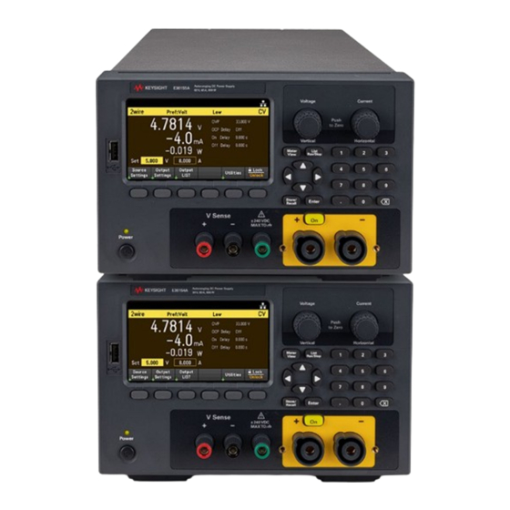
- Page 1 Autoranging DC Power Supplies E36150 Series This manual contains service information, performance verification and adjustment procedures for the E36150 Series autoranging DC power supplies. SERVICE GUIDE...
-
Page 2: Table Of Contents
Test record form - Keysight E36154A Test record form - Keysight E36155A Calibration Adjustment Procedures Closed–case electronic calibration Calibration interval Calibration adjustment process Calibration security Calibration count Calibration message Saving calibration data Calibration auto save Calibration Test Setup Keysight E36150 Series Service Guide... - Page 3 Calibration procedure Save the calibration data Keysight E36150 Series Service Guide...
-
Page 4: Notices
No part of this manual may be reproduced in any form or by any means (including electronic storage and retrieval or translation into a foreign language) without prior agreement and written consent from Keysight Technologies as governed by United States and international copyright laws. -
Page 5: U.s. Government Rights
Declarations of Conformity Declarations of Conformity for this product and for other Keysight products may be downloaded from the Web. Go to https://regulations.about.keysight.com/DoC/default.htm. You can then search by product number to find the latest Declaration of Conformity. Keysight E36150 Series Service Guide... -
Page 6: Safety Information
A WARNING notice denotes a hazard. It calls attention to an operating procedure, practice, or the like that, if not correctly per- formed or adhered to, could result in personal injury or death. Do not proceed beyond a WARNING notice until the indicated con- ditions are fully understood and met. Keysight E36150 Series Service Guide... -
Page 7: Service And Maintenance
User Replaceable Parts Battery Replacement Disassembly This chapter provides the specifications and service information on cleaning, troubleshooting, repair, and replaceable parts of the E36150 Series. This chapter also explains how to assemble and disassemble the E36150 Series. Keysight E36150 Series Service Guide... -
Page 8: Specifications And Characteristics
Types of service available If your instrument fails during the warranty period, Keysight Technologies will repair or replace it under the terms of your warranty. After your warranty expires, Keysight offers repair services at competitive prices. You also have the option to purchase a service contract that extends the coverage after the standard warranty expires. -
Page 9: Troubleshooting
If required, contact a Keysight Technologies Sales and Service office to arrange for proper cleaning to ensure that safety features and performance are maintained. Electrostatic Discharge (ESD) precautions Almost all electrical components can be damaged by electrostatic discharge (ESD) during handling. Component damage can occur at electrostatic discharge voltages as low as 50 V. -
Page 10: Battery Replacement
(see red arrow below). The top of the small spring clips should be visible after the battery is seated (see red circle below). 5. Replace the top cover when finished. 6. Reset the date and time. Properly dispose of the old battery in accordance with local laws and regulations. Keysight E36150 Series Service Guide... -
Page 11: Disassembly
9105) from the front panel. Remove four Pozi screws (KPN 0515- 1055) from the front panel using a Pozi M4 bit. Pull out the front panel To install back the front panel, perform the above steps in reverse order. Keysight E36150 Series Service Guide... -
Page 12: Removing/Installing The Knob (Kpn 54964-47450)
Cover both side with the plastic cap (KPN 5042-6815). Secure both side of the strap handle with 2 (M5*10) screws (KPN 0515- 1384) Removing/Installing the optional GPIB interface Refer to the E36150 Series User's Guide for details. Keysight E36150 Series Service Guide... -
Page 13: Verification And Adjustments
Test Record Forms Calibration Adjustment Procedures This chapter contains the performance verification procedures which verify that the E36150 Series is operating within its published specifications. This chapter also provides information on adjustments performed after a performance verification fails. Keysight E36150 Series Service Guide... -
Page 14: Performance Verification
2. 1.125 Ω for 30 V, 26.667 A PARD DSR-2000W1R2J-F-V1 Fixed Load Wirewound resistor 2000 W, for PARD verification: MF Power Resistor (E36155A) 1. 0.5 Ω for 20 V, 40 A PARD DSR-2000WR6J-F-V1 2. 4.5 Ω for 60 V, 13.333 A PARD DSR-2000W5RJ-F-V1 Keysight E36150 Series Service Guide... -
Page 15: Test Considerations
“Wait” statements can be used in the test program if the test system is faster than the power system. Keysight E36150 Series Service Guide... -
Page 16: Verification Test Setups
The following figures show the verification test set-ups. Connect all leads to the output terminal as shown below. A LAN, USB, or GPIB cable is needed for readback data. CC Verification Test Setup CV Verification Test Setup CV Ripple and Noise Verification Test Setup Keysight E36150 Series Service Guide... -
Page 17: Constant Voltage (Cv) Verification
The output status of the power supply should be “CV”. If it isn’t, adjust the load so that the output current drops slightly. 6. Record the output voltage reading from the DMM as V load Keysight E36150 Series Service Guide... - Page 18 9. The difference between the DMM readings in steps 7 and 8 is the CV line regulation (V ), which lowline highline should not exceed the value listed in the Test Record Form for the appropriate model under “CV Line Regulation”. Keysight E36150 Series Service Guide...
- Page 19 1 kHz. The output status of the power supply should be “CV”. If it isn’t, adjust the load so that the output current drops slightly. 7. Program the load's transient current level to the higher current value indicated in Table 2-4, and turn the transient generator on. Keysight E36150 Series Service Guide...
- Page 20 2. Connect a fixed load, differential amplifier, and an oscilloscope (AC coupled) to the output terminals (see Ripple and Noise Test Setup). 3. Use an appropriate load resistor (see the fixed load value in the Recommended Test Equipment list) to keep the power system at instrument settings specified in Table 2-5. Keysight E36150 Series Service Guide...
- Page 21 Test Record Form for the appropriate model under “CV Ripple and Noise, rms”. Table 2-5 CV ripple and noise verification instrument settings Model DUT settings Fixed load Voltage (V) Current (A) Value E36154A 1.125 0.125 E36155A Keysight E36150 Series Service Guide...
-
Page 22: Constant Current (Cc) Verification
6. The readings should be within the limits specified in the Test Record Form for the appropriate model under “Current Programming" and "Current Readback (High Range)". Table 2-6 Current programming and readback accuracy instrument settings Model DUT settings Voltage (V) Current (A) E36154A E36155A Keysight E36150 Series Service Guide... - Page 23 The output status of the power supply should be “CC”. If it isn’t, adjust the load so that the output voltage drops slightly. 6. Record the current reading (I ), by dividing the voltage reading on the DMM by the resistance of the current load monitoring resistor. Keysight E36150 Series Service Guide...
- Page 24 11. The difference between the DMM reading in steps 8 and 10 is the CC line regulation, which should not exceed the value listed in the Test Record Form for the appropriate model under “CC Line Regulation”. Keysight E36150 Series Service Guide...
- Page 25 103.5 VAC 126.5 VAC 115 VAC 26.67 207 VAC 253 VAC 230 VAC E36155A 13.33 90 VAC 110 VAC 100 VAC 13.33 103.5 VAC 126.5 VAC 115 VAC 13.33 207 VAC 253 VAC 230 VAC Keysight E36150 Series Service Guide...
-
Page 26: Test Record Forms
Max V, 0 A I 0 - 0.02 A ______________ I 0 + 0.02 A Maximum Current measured over interface Max V, 80 A I max - 0.1 A ______________ I max + 0.1 A Keysight E36150 Series Service Guide... - Page 27 CC Line Regulation (I lowline - I highline ) 26.67 A at 30 V Max V, 26.67 A -28.6 mA ______________ 28.6 mA 80 A at 10 V Max V, 80 A -82 mA ______________ 82 mA Keysight E36150 Series Service Guide...
-
Page 28: Test Record Form - Keysight E36155A
Max V, 0 A I 0 - 0.004 A ______________ I 0 + 0.004 A Maximum current measured over interface Max V, 0.4 A I max - 0.0044 A ______________ I max + 0.0044 A Keysight E36150 Series Service Guide... - Page 29 CC Line Regulation (I lowline - I highline ) 13.33 A at 60 V Max V, 13.33 A -15.33 mA ______________ 15.33 mA 40 A at 20 V Max V, 40 A -42 mA ______________ 42 mA Keysight E36150 Series Service Guide...
-
Page 30: Calibration Adjustment Procedures
Calibration Adjustment Procedures This chapter includes calibration adjustment procedures for Keysight E36150 Series Autoranging DC Power Supply. Perform the verification tests before calibrating your instrument. If the instrument passes the verification tests, the unit is operating within its calibration limits and does not need to be re-calibrated. -
Page 31: Calibration Count
You can only store the calibration message when the instrument is unsecured, but you can execute the CALibration:STRing? query regardless of whether the instrument is secured. A new calibration message overwrites the previous message, and messages over 40 characters are truncated. Keysight E36150 Series Service Guide... -
Page 32: Saving Calibration Data
To enable or disable the CAL auto Save feature, send CAL:ASAV ON or CAL:ASAV OFF. To query the CAL auto Save state, send CAL:ASAV? Calibration Test Setup The following figures show the verification test set-ups. Connect all leads to the output terminal as shown below. CC CalibrationTest Setup CV Calibration Test Setup Keysight E36150 Series Service Guide... - Page 33 Note: Wait 2 minutes for the voltage to stabilize before measuring the voltage with DMM. 5. Enter the measured value, and press Next. 6. Read DONE or FAIL on the display. 7. Press Cal Save. Keysight E36150 Series Service Guide...
- Page 34 Note: Wait 3 minutes for the current to stabilize before measuring the current with DMM. 6. Enter the measured value, and press Next. 7. Read DONE or FAIL on the display. 8. Press Cal Save. Keysight E36150 Series Service Guide...
- Page 35 Auto Save is on. – To save the Cal data: CAL:SAVE – To enable the Cal Auto Save: CAL:ASAVE ON – To exit Cal State: CAL:SEC:STAT 1 <code> Keysight E36150 Series Service Guide...
- Page 36 This information is subject to change without notice. © Keysight Technologies 2022, 2023 Edition 2, February 2023 Printed in Malaysia E36151-90009 www.keysight.com...
Need help?
Do you have a question about the E36150 Series and is the answer not in the manual?
Questions and answers