Table of Contents
Advertisement
Quick Links
Advertisement
Table of Contents

Related Manuals for Keysight Technologies RP7900 Series


Summary of Contents for Keysight Technologies RP7900 Series
-
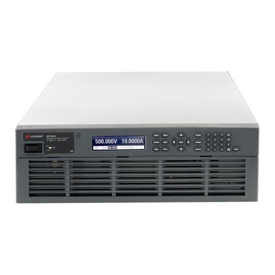
Page 1: Power System
Keysight Regenerative Power System RP7900 Series Operating and Service Guide... -
Page 3: Table Of Contents
Excessive Dynamic Protection Output Quadrants Dimensions - RP795xA and RP796xA 2 Installing the Instrument Before Installation or Use Inspect the Unit Check for Items Supplied Review Safety Information Observe Environmental Conditions Provide Adequate Air Flow Keysight RP7900 Series Operating and Service Guide... - Page 4 Using Sockets Interface Lockout 4 Using the Regenerative Power System Programming the Output Set the Output Priority Mode Set the Output Voltage Set the Output Current Set the Slew Rate Set the Output Resistance Keysight RP7900 Series Operating and Service Guide...
- Page 5 Periodically Retrieve the Data Terminate the Elog Making Measurements Average Measurements Measurement Sweep Measurement Windowing A-hour & W-hour measurement Digitized Measurements Measurement Triggering Programming the Digital Port Digital Control Port Bi-Directional Digital I/O Digital Input Keysight RP7900 Series Operating and Service Guide...
- Page 6 DIGital Subsystem DISPlay Subsystem FETCh Subsystem FORMat Subsystem FUNCtion Command HCOPy Subsystem IEEE-488 Common Commands INITiate Subsystem INSTrument Subsystem LIST Subsystem LXI Subsystem MEASure Subsystem OUTPut Subsystem POWer Query SENSe Subsystem [SOURce] Subsystem Keysight RP7900 Series Operating and Service Guide...
- Page 7 Calibration Interval Calibration Setups Test Considerations Calibration Procedure Test Record Forms 7 Service and Maintenance Introduction Repair Service Available Before Returning the Unit Repackaging for Shipment Cleaning Self-Test Procedure Power-On Self-Test User-Initiated Self-Test Keysight RP7900 Series Operating and Service Guide...
- Page 8 Installing the Keysight SD1000A Safety Disconnect System Keysight SD1000A-to-RP7900 Connections External Control Connections Operating the Keysight SD1000A Safety Disconnect System Controlling the SDS Using the RP7900 series Power Supply Controlling the SDS Using Externally Wired Controls Index Keysight RP7900 Series Operating and Service Guide...
-
Page 9: Legal And Safety Information
No part of this manual may be reproduced in any form or by any means (including electronic storage and retrieval or translation into a foreign language) without prior agreement and written consent from Keysight Technologies as governed by United States and international copyright laws. Keysight Technologies... - Page 10 Certification Keysight Technologies certifies that this product met its published specifications at time of shipment from the factory. Keysight Technologies further certifies that its calibration measurements are traceable to the United States National Institute of Standards and Technology, to the extent allowed...
-
Page 11: Safety Symbols
This equipment has been conformity assessed for use in business environments. In a residential environment this equipment may cause radio interference. This EMC statement applies to the equipment only for use in business environments. Keysight RP7900 Series Operating and Service Guide... -
Page 12: Safety Notices
Failure to comply with these precautions or with specific warnings or instructions elsewhere in this manual violates safety standards of design, manufacture, and intended use of the instrument. Keysight Technologies assumes no liability of the customer’s failure to comply with the requirements. - Page 13 To prevent electric shock, always disconnect the AC mains before cleaning. Use a dry cloth or one slightly dampened with water to clean the external case parts. Do not use detergent or chemical solvents. Do not attempt to clean internally. Keysight RP7900 Series Operating and Service Guide...
- Page 14 Legal and Safety Information In Case of Damage Instruments that are not functioning correctly, appear damaged or defective should be made inoperative and secured against unintended operation until they can be repaired by qualified service personnel. Keysight RP7900 Series Operating and Service Guide...
-
Page 15: Quick Reference
Keysight RP7900 Series Operating and Service Guide Quick Reference Legal and Safety Information Introduction to the Instrument Front Panel Menu Reference Command Quick Reference Model Features and Options Specifications and Characteristics - RP793xA, RP794xA Specifications and Characteristics - RP795xA, RP796xA This document includes user, service, and programming information for the Keysight Regenerative Power System (RPS) Family. -
Page 16: Introduction To The Instrument
Two-quadrant operation provides current sourcing and sinking capability 100% rated current-sink capability 5 kW and 10 kW rated models Measurement features 5.12 microsecond sample rate Real-time power measurements A-hour & W-hour measurement Digitized measurement capability Keysight RP7900 Series Operating and Service Guide... -
Page 17: Front Panel At A Glance
2. Display - Turns off after 1 hour of inactivity. Press any key to restore the display. 3. System keys - Select metering function. Access front panel command, help, and error menus. 4. Navigation keys - Move the cursor to a menu item. Select the highlighted menu item. Keysight RP7900 Series Operating and Service Guide... -
Page 18: Rear Panel At A Glance
6. USB - USB interface connector. 7. LAN - 10/100/1000 Base-T Left LED indicates activity. Right LED indicates link integrity. 8. Master/slave - Master/slave connectors - for grouping paralleled units. 9. Termination switches - Specifies master/slave termination types. Keysight RP7900 Series Operating and Service Guide... -
Page 19: Front Panel Display At A Glance
If the Current limit is reached, the output will no longer be operating in constant voltage mode, but will be in current limit mode. In this case, the actual output voltage will now be less than the output voltage setting. Keysight RP7900 Series Operating and Service Guide... -
Page 20: Front Panel Keys At A Glance
The Backspace key deletes digits as it backspaces over them. The Enter key enters a value. If you exit a field without pressing the Enter key, the value is ignored. Press the Help key to get context sensitive help. Keysight RP7900 Series Operating and Service Guide... -
Page 21: Front Panel Menu Reference
Configures individual list step settings Reset Aborts the list and resets all list settings Repeat Specifies number of Arb repetitions, or continuous Arb Terminate Specifies Arb termination conditions Config Configures individual Arb settings Keysight RP7900 Series Operating and Service Guide... - Page 22 Reads status data from the digital port of the SDS unit Output Sets the state of the external output signals of the SDS unit Preferences Clock Sets the real-time clock Display Configures the screen saver and start-up meter view Keysight RP7900 Series Operating and Service Guide...
- Page 23 Saves the calibration data Enables/disables USB, GPIB, and LAN services Sanitize Performs NISPOM secure erase of all user data Update Password protected firmware update Password Changes the admin password About Displays model, options, serial number, and firmware Keysight RP7900 Series Operating and Service Guide...
-
Page 24: Command Quick Reference
Returns the High level of a pulse waveform. :LOW? Returns the Low level of a pulse waveform. :MAXimum? Returns the maximum or minimum value. :MINimum? :POWer [:DC]? [<start_index>, <points>] Returns the averaged measurement. Keysight RP7900 Series Operating and Service Guide... - Page 25 Resets the instrument to pre-defined values that are either typical or safe. *SAV <value> Saves the instrument state to one of ten non-volatile memory locations. *SRE <value> Service request enable command and query. *STB? Status byte query. *TRG Trigger command. Keysight RP7900 Series Operating and Service Guide...
- Page 26 Takes a measurement; returns the minimum current. :POWer [:DC]? Takes a measurement; returns the averaged power. :MAXimum? Takes a measurement; returns the maximum power. :MINimum? Takes a measurement; returns the minimum power. :VOLTage Keysight RP7900 Series Operating and Service Guide...
- Page 27 :DELay <value> Sets the watchdog delay time. :RELay :LOCK [:STATe] 0|OFF|1|ON Enables or disables the locked relay state of the SD1000A unit. SENSe :AHOur :RESet Resets the amp-hour or watt-hour measurement to zero. :ELOG Keysight RP7900 Series Operating and Service Guide...
- Page 28 Sets the output current when in current priority mode :TRIGgered [:AMPLitude] <value> Sets the triggered output current :BWIDth :RANGe 0 | 1 Sets the current compensation. (RP793xA,RP794xA) :LEVel 0 | 1, <value> Sets the compensation frequency. (RP793xA, RP794xA) :LIMit Keysight RP7900 Series Operating and Service Guide...
- Page 29 :POINts? Returns the number of list points. :DWELl <value>{,<value>} Specifies the dwell time for each list step. :POINts? Returns the number of list points. :STEP ONCE|AUTO Specifies how the list responds to triggers. Keysight RP7900 Series Operating and Service Guide...
- Page 30 Sets the over-voltage protection level. :LOW [:LEVel] <value> Sets the low-voltage protection level. (RP793xA, RP794xA) :DELay <value> Sets the low-voltage protection delay. (RP793xA, RP794xA) :STATe 0|OFF|1|ON Enables or disables low-voltage protection. (RP793xA, RP794xA) :RESistance [:LEVel] Keysight RP7900 Series Operating and Service Guide...
- Page 31 Selects the connection mode at power-on. :DIGital :DATA :INPut? Reads the SDS digital port signals. :OUTPut <value> Sets the SDS digital output signals. :ENABle 0|OFF|1|ON Enables or disables the SDS unit. :STATus? Returns the SDS status. Keysight RP7900 Series Operating and Service Guide...
- Page 32 :SOURce <source> Selects the trigger source for external data logging: BUS |EXTernal |IMMediate |PIN<1-7> :TRANsient [:IMMediate] Generates an immediate trigger. :SOURce <source> Selects the trigger source for the transient system: BUS |EXTernal |IMMediate |PIN<1-7> Keysight RP7900 Series Operating and Service Guide...
-
Page 33: Model Features And Options
Output resistance Yes* Yes* programming Voltage & current measurement Amp-hour, Watt-hour, & power measurement Array readback Adjustable sampling External data logging Under-voltage protection SDS unit available *Requires firmware version B.03.02.1232 and up. Keysight RP7900 Series Operating and Service Guide... -
Page 34: Options/Accessories
Keysight RP7909A Rack mount and slide kit - for mounting units in 19-inch EIA cabinets Keysight 1CP108A Rack mount flange kit with handles Keysight E3663AC Basic rail kit for system II Keysight instrument racks Keysight RP7900 Series Operating and Service Guide... -
Page 35: Specifications And Characteristics - Rp793Xa, Rp794Xa
4 Time to recover to within the settling band following a step change from 40% to 90% of full load with a 35 μs current rise time Keysight RP7900 Series Operating and Service Guide... -
Page 36: Supplemental Characteristics - Rp793Xa, Rp794Xa
Rise/fall time 10% to 90% of step: 300 µs 180 µs 300 µs 180 µs 190 µs Settling time to 0.1% of step:: 960 µs 500 µs 960 µs 500 µs 550 µs Keysight RP7900 Series Operating and Service Guide... -
Page 37: Common Characteristics
0°C to 55°C (Maximum continuous power available is derated at 1% of rating per degree C from 40°C to 55°C) Relative humidity: 95% or less (non-condensing) Altitude: Up to 2000 meters Storage temperature: -30°C to 70°C Keysight RP7900 Series Operating and Service Guide... - Page 38 No output terminal may be more than ±60 VDC from any other terminal or chassis ground. For 80 & 160 VDC models: No output terminal may be more than ±240 VDC from any other terminal or chassis ground. Keysight RP7900 Series Operating and Service Guide...
-
Page 39: Output Impedance Graphs
20 V, 5 kW unit (@ 10 V, 200 A 6" leads, local sense) 20 V, 10 kW unit (@ 10 V, 400 A, 6" leads, local sense) 20 V, 10 kW unit (@ 10 V, 400 A, 6" leads) Keysight RP7900 Series Operating and Service Guide... - Page 40 Voltage Priority Mode (160 V units) Current Priority Mode (160 V units) 160 V, 10 kW unit (@ 80 V, 125 A 6" leads, local sense) 160 V, 10 kW unit (@ 80 V, 125 A, 6" leads) Keysight RP7900 Series Operating and Service Guide...
-
Page 41: Inductive Load Boundary For Current Priority Mode
Compensation for Current Priority Mode 0 (20 V units) Compensation for Current Priority Mode 1 (20 V units) 20 V, 5 kW unit 20 V, 5 kW unit 20 V, 10 kW unit 20 V, 10 kW unit Keysight RP7900 Series Operating and Service Guide... - Page 42 Compensation for Current Priority Mode 0 (80 V units) Compensation for Current Priority Mode 1 (80 V units) 80 V, 5 kW unit 80 V, 5 kW unit 80 V, 10 kW unit 80 V, 10 kW unit Keysight RP7900 Series Operating and Service Guide...
-
Page 43: Capacitive Load Boundary For Voltage Priority Mode
CV mode stability. There are no absolute limits for DUT capacitance, as the stability is also a function of ESR. Refer to Load Capacitance and Lead Inductance Considerations for details. Keysight RP7900 Series Operating and Service Guide... - Page 44 20 V, 5 kW unit; comp 0 20 V, 5 kW unit; comp 1 20 V, 5 kW unit; comp 1 20 V, 5 kW unit; comp 2 20 V, 5 kW unit; comp 2 Keysight RP7900 Series Operating and Service Guide...
- Page 45 20 V, 10 kW unit; comp 0 20 V, 10 kW unit; comp 1 20 V, 10 kW unit; comp 1 20 V, 10 kW unit; comp 2 20 V, 10 kW unit; comp 2 Keysight RP7900 Series Operating and Service Guide...
- Page 46 80 V, 5 kW unit; comp 0 80 V, 5 kW unit; comp 1 80 V, 5 kW unit; comp 1 80 V, 5 kW unit; comp 2 80 V, 5 kW unit; comp 2 Keysight RP7900 Series Operating and Service Guide...
- Page 47 80 V, 10 kW unit; comp 0 80 V, 10 kW unit; comp 1 80 V, 10 kW unit; comp 1 80 V, 10 kW unit; comp 2 80 V, 10 kW unit; comp 2 Keysight RP7900 Series Operating and Service Guide...
- Page 48 160 V, 10 kW unit; comp 0 160 V, 10 kW unit; comp 1 160 V, 10 kW unit; comp 1 160 V, 10 kW unit; comp 2 160 V, 10 kW unit; comp 2 Keysight RP7900 Series Operating and Service Guide...
-
Page 49: Small Signal Programming Response (All Models)
"% of range added to spec value" as follows: 20 V x 0.006% = 1.2 mV. Add this number to the offset part of the measurement accuracy specification: 2 mV + 1.2 mV. The new voltage measurement accuracy is 0.02% + 3.2 mV at 0.003 NPLC. Keysight RP7900 Series Operating and Service Guide... -
Page 50: Excessive Dynamic Protection
125 A 62.5 A 6 mΩ RP7935A /RP7945A 80 V 40 V 0.75 V 250 A 125 A 3 mΩ RP7936A /RP7946A 160 V 80 V 1.5 V 125 A 62.5 A 12 mΩ Keysight RP7900 Series Operating and Service Guide... -
Page 51: Dimensions - Rp793Xa And Rp794Xa
1 Quick Reference Dimensions - RP793xA and RP794xA Keysight RP7900 Series Operating and Service Guide... -
Page 52: Specifications And Characteristics - Rp795Xa, Rp796Xa
4 Time to recover to within the settling band following a step change from 50% to 100% of full load at the maximum slew rate Keysight RP7900 Series Operating and Service Guide... -
Page 53: Supplemental Characteristics - Rp795Xa, Rp796Xa
1 Up programming with full resistive load and a step change from 0.1% to 100% of rated output 2 Down programming with no load and a step change from 100% to 0.1% of rated output 3 Equivalent to 10 feet of load leads Keysight RP7900 Series Operating and Service Guide... -
Page 54: Common Characteristics
Typical low-level current = 2 mA @ 0 V (internal 2.2k pull-up) Typical high-level leakage current = 0.12 mA @ 16.5 VDC Pin 8: Pin 8 is common (internally connected to chassis ground) Keysight RP7900 Series Operating and Service Guide... -
Page 55: Output Impedance Graphs
All the voltage priority impedance graphs are in High bandwidth setting. There are only very minor differences at low frequencies on the graphs in Low bandwidth setting. The bandwidth setting has no effect in current priority mode. Keysight RP7900 Series Operating and Service Guide... - Page 56 500 V, 10 kW unit (@ 250 V, 20 A) 500 V, 10 kW unit (@ 100 V, 15 A) 950 V, 10 kW unit (@ 500 V, 5 A) 950 V, 10 kW unit (@ 100 V, 15 A) Keysight RP7900 Series Operating and Service Guide...
-
Page 57: Inductive Load Boundary For Current Priority Mode
Operation below the marginal stability line may result in output instability. Note that increased load resistance allows increased output inductance. 500 V units 950 V units 950 V, 10 kW unit 500 V, 10 kW unit 500 V, 5 kW unit Keysight RP7900 Series Operating and Service Guide... -
Page 58: Capacitive Load Boundary For Voltage Priority Mode
500 V, 10 kW unit 500 V, 5 kW unit Voltage Programming Response (All Models) The following graph shows the output voltage programming response characteristic. This applies for small signals only, under no load conditions. Keysight RP7900 Series Operating and Service Guide... -
Page 59: Excessive Dynamic Protection
250 V 20 A 10 A 0.4 Ω RP7952A /RP7962A 500 V 250 V 40 A 20 A 0.2 Ω RP7953A/RP7963A 950 V 500 V 16 V 20 A 10.5 A 0.8 Ω Keysight RP7900 Series Operating and Service Guide... -
Page 60: Dimensions - Rp795Xa And Rp796Xa
1 Quick Reference Dimensions - RP795xA and RP796xA Keysight RP7900 Series Operating and Service Guide... -
Page 61: Installing The Instrument
Keysight RP7900 Series Operating and Service Guide Installing the Instrument Before Installation or Use Rack Mounting Single Unit Connections Multiple Unit Connections Interface Connections Heavy Weight Danger to hands and feet. To avoid personal injury and damage to the instrument, always use a sturdy cart or other suitable device to move the instrument. -
Page 62: Before Installation Or Use
Ferrite core for power cord For earlier models RP7961A, RP7962A, RP7963A Keysight 9170-2578 Calibration certificate Calibration certificate referenced to serial number None Parts marked with an asterisk are included in Cover KIt, p/n 5066-1930. Keysight RP7900 Series Operating and Service Guide... -
Page 63: Review Safety Information
12 inches (30.5 cm) at the front and back of the unit for adequate air circulation. Stacking Instruments Never stack more than three instruments on top of one another in a free-standing installation. Keysight RP7900 Series Operating and Service Guide... -
Page 64: Rack Mounting
Install the stationary part of each slide rail to the sides of the rack frame using the four screws provided (2680-0104). 4. Install the two flange mounts to the front panel corners of the instrument using the six screws provided (0515-1114). Keysight RP7900 Series Operating and Service Guide... - Page 65 5. Install four clip nuts on the front of the rack frame for attaching the front panel (0590-0804). 6. Slide the instrument into the rack. 7. Attach the front panel to the instrument to the rack using the four dress screws provided (3030- 1768). Keysight RP7900 Series Operating and Service Guide...
-
Page 66: Single Unit Connections
Either a delta-type or a Y-type AC mains distribution can be used, provided that the correct line-to-line voltage is applied (see above). Do not connect the neutral wire on Y-type AC mains distribution. An earth-ground to chassis-ground connection through a separate conductor must always be provided. Keysight RP7900 Series Operating and Service Guide... - Page 67 (p/n 9170-2578) to reduce RFI interference. Place the core as close as possible to the input cover as shown. Place a tie-wrap behind the core to prevent it from sliding down the power cord. Keysight RP7900 Series Operating and Service Guide...
-
Page 68: Output Connections
* For the 20 V RPS units only, the sense leads are buffered so that there is virtually no change in the open-circuit output voltage if the sense cable is not installed or becomes disconnected. Keysight RP7900 Series Operating and Service Guide... -
Page 69: Wire Size
Note 1 Ampacity is based on a single conductor in free air, 26-30 °C ambient temperature with the conductor rated at 60 °C. Ampacity decreases at higher temperatures. Note 2 Resistance is in ohms/1000 feet, at 20 °C wire temperature. Keysight RP7900 Series Operating and Service Guide... -
Page 70: Single Load Connections
4. Attach the safety cover to the rear panel. Note that heavy wiring cables must have some form of strain relief to prevent bending the safety cover or bus bars. High Voltage Models - RP795xA and RP796xA Tightening torque of the output bolts cannot exceed 10.8 Nm (8 lb-ft). Keysight RP7900 Series Operating and Service Guide... -
Page 71: Multiple Load Connections
Connect each load to the distribution terminals separately. Remote voltage sensing is recommended under these circumstances. Sense either at the remote distribution terminals or, if one load is more sensitive than the others, directly at the critical load. Keysight RP7900 Series Operating and Service Guide... -
Page 72: Remote Sense Connections
Then make your connections as shown in the following figure. Connect the output terminals to the load using separate connecting wires. Keep the wire-pair as short as possible and twist or bundle it to reduce lead inductance and noise pickup. Keysight RP7900 Series Operating and Service Guide... - Page 73 The voltage at the previous remote sense point (usually at the load) will drop by an amount given by the following equation: Δ V= I x (total resistance of load wiring) Keysight RP7900 Series Operating and Service Guide...
-
Page 74: Additional Load Considerations - All Models
Note that programming into an external output capacitor may cause the RPS to briefly enter constant current operating mode, which adds additional response time. By setting the proper voltage slew rate when using an external capacitor, it may be possible to prevent mode crossover into constant current. Keysight RP7900 Series Operating and Service Guide... -
Page 75: Additional Load Considerations - Rp793Xa, Rp794Xa
DUT is of a resistive or high impedance nature and may have some local bypass capacitance near its own terminals. Remote sensing at the DUT terminals is recommended if accurate DC voltage regulation is required. Keysight RP7900 Series Operating and Service Guide... - Page 76 Generally, a capacitor with low ESR in parallel with a capacitor with high ESR allows for good stability, minimized transient response voltage deviation, as well as good voltage noise filtering. Keysight RP7900 Series Operating and Service Guide...
- Page 77 RPS unit's steady state rating can occur, potentially damaging the DUT. After a short delay, the excessive current flow will cause over-current protection to engage - disabling the output of the RPS. Keysight RP7900 Series Operating and Service Guide...
-
Page 78: Multiple Unit Connections
+ and - output leads from the bus bars to the load. A symmetrical arrangement of separate load-wire pairs of equal length connecting to a common load point is highly recommended. This provides the best possible dynamic response. Keysight RP7900 Series Operating and Service Guide... - Page 79 Size the load cables according to the current rating of the unit. Double the cables on the 10 kW units so that cable inductance scales with the 5 kW units. Plus cables should be bundled with minus cables. Keysight RP7900 Series Operating and Service Guide...
-
Page 80: Master/Slave Connections - For All Models
"unterminated". If only two units are connected in a master/slave configuration, both units must have their switches set to "terminated". A current-sharing fault (CSF) may occur if the switches are not set incorrectly. Keysight RP7900 Series Operating and Service Guide... -
Page 81: Current Sharing Connections - Rp795Xa, Rp796Xa
A ferrite core is also provided to comply with the EMC IEC61326-1 standard. The ferrite core does not affect the functionality of this product. The following figures detail the sharing cable incorporated with the safety cover and the ferrite core. Keysight RP7900 Series Operating and Service Guide... -
Page 82: Series Connections
SHOCK HAZARD/LETHAL VOLTAGES Series connections are not permitted for many reasons. One of the primary reasons for models RP795xA and RP796xA, for example, is that floating voltages cannot exceed the isolation ratings given in the RP795xA, RP796xA characteristics tables. Keysight RP7900 Series Operating and Service Guide... -
Page 83: Interface Connections
3. You can now use Interactive IO within the Connection Expert to communicate with your instru- ment, or you can program your instrument using the various programming environments. USB Connections The following figure illustrates a typical USB interface system. Keysight RP7900 Series Operating and Service Guide... -
Page 84: Lan Connections - Site And Private
A private LAN is a network in which LAN-enabled instruments and computers are directly connected, and not connected to a site LAN. They are typically small, with no centrally-managed resources. The following figure illustrates a typical private LAN system. Keysight RP7900 Series Operating and Service Guide... -
Page 85: Digital Port Connections
AWG 14 (1.5 mm 2 ) to AWG 28 (0.14 mm 2 ). Wire sizes smaller than AWG 24 (0.25 mm 2 ) are not recommended. Strip wire insulation back 7 mm. Keysight RP7900 Series Operating and Service Guide... -
Page 86: Interface Cover Installation
2. Connect the LAN, USB, GPIB cable, and digital IO wires (GPIB shown) to the appropriate rear panel connector. 3. Install the ESD cover to the back of the unit using the two screws. Make sure the cover is inserted into the flange. Keysight RP7900 Series Operating and Service Guide... -
Page 87: Getting Started
Keysight RP7900 Series Operating and Service Guide Getting Started Using the Front Panel Remote Interface Configuration... -
Page 88: Using The Front Panel
AC power connected, and if it is green, the instrument is on. If a self-test error occurs, a message is displayed on the front panel. For other self- test errors, see Service and Maintenance for instructions on returning the instrument for service. Keysight RP7900 Series Operating and Service Guide... -
Page 89: Set The Output Voltage
Enter the desired setting using the numeric keypad. Then press Enter. If you make a mistake, either use the backspace key to delete the number, press Back to back out of the menu, or press Meter to return to meter mode. Keysight RP7900 Series Operating and Service Guide... -
Page 90: Set The Output Current
Enter. If you make a mistake, either use the backspace key to delete the number, press Back to back out of the menu, or press Meter to return to meter mode. Keysight RP7900 Series Operating and Service Guide... -
Page 91: Set Over-Voltage Protection
Press the right arrow navigation key > to traverse the menu until the Protect command is highlighted. Press the Select key to access the Protect commands. Since the OVP command is already highlighted, press the Select key to access the OVP dialog. Keysight RP7900 Series Operating and Service Guide... -
Page 92: Enable The Output
Press the Help key at the lowest menu level to display help information about the menu function controls. Whenever a limit is exceeded or any other invalid configuration is found, the instrument will display a message, including Error code information. Press Meter or Back to exit Help. Keysight RP7900 Series Operating and Service Guide... -
Page 93: Remote Interface Configuration
This setting is non-volatile; it will not be changed by power cycling or *RST. Use the front panel menu to change the GPIB address: Keysight RP7900 Series Operating and Service Guide... -
Page 94: Lan Configuration
You can also reset the LAN to the as-shipped (default) settings. This returns ALL LAN settings to the as-shipped values and restarts networking. All default LAN settings are listed under Non-volatile Settings. Keysight RP7900 Series Operating and Service Guide... -
Page 95: Modifying The Lan Settings
"192.168.020.011" is actually equivalent to decimal "192.168.16.9" because ".020" is interpreted as "16" expressed in octal, and ".011" as "9". To avoid confusion, use only decimal values from 0 to 255, with no leading zeros. Keysight RP7900 Series Operating and Service Guide... - Page 96 "192.168.020.011" is actually equivalent to decimal "192.168.16.9" because ".020" is interpreted as "16" expressed in octal, and ".011" as "9". To avoid confusion, use only decimal values from 0 to 255, with no leading zeros. Keysight RP7900 Series Operating and Service Guide...
- Page 97 Check or uncheck the services that you wish to enable or disable. The configurable services include: VXI-11, Telnet, Web control, Sockets, mDNS, and HiSLIP. You must enable Web control if you wish to remotely control your instrument using its built-in Web interface. Keysight RP7900 Series Operating and Service Guide...
-
Page 98: Using The Web Interface
If desired, you can control access to the Web interface using password protection. As shipped, no password is set. To set a password, click on the "gear" icon. Refer to the on-line help for additional information about setting a password. Keysight RP7900 Series Operating and Service Guide... -
Page 99: Using Telnet
Not available Enable or disable the interfaces by checking or unchecking the following items: Enable LAN, Enable GPIB, and Enable USB If you cannot access the Admin menu, it may be password protected. Keysight RP7900 Series Operating and Service Guide... -
Page 101: Using The Regenerative Power System
Keysight RP7900 Series Operating and Service Guide Using the Regenerative Power System Programming the Output Parallel Operation Current Sinking Operation Programming Output Protection Programming Output Transients Sequencing the Output Making Measurements External Data Logging Programming the Digital Port System-Related Operations... -
Page 102: Programming The Output
Select either Voltage priority or Current priority. Then press Select. When switching between voltage priority and current priority mode, the output is turned off and the output settings revert to their Power-on or RST values. Keysight RP7900 Series Operating and Service Guide... -
Page 103: Set The Output Voltage
Specify the low voltage limit. Then press Select. Set the Output Current When the unit is in voltage priority mode, you can specify a positive and negative current limit, which limits the output current at the specified value. Keysight RP7900 Series Operating and Service Guide... -
Page 104: Set The Slew Rate
Output resistance programming is mainly used in battery testing applications and only applies in voltage priority mode. It is used to emulate the internal resistance of a non-ideal voltage source such as a battery. Values are programmed in ohms. Keysight RP7900 Series Operating and Service Guide... -
Page 105: Set The Output Bandwidth - Rp795Xa, Rp796Xa
5 kW Models 10 kW Models 950 V Models High1 0 to 80 μF 0 to 80 μF 0 to 40 μF 0 to 100,000 μF 0 to 100,000 μF 0 to 50,000 μF Keysight RP7900 Series Operating and Service Guide... -
Page 106: Set The Output Bandwidth - Rp793Xa, Rp794Xa
1.4 kHz 190 µs/2.3 ms 205 µs/1.5 ms Comp 2 full CC load, 0-100% of rating 900 Hz 350 µs/3.8 ms 360 µs/1.25 ms The following table describes the CV small signal bandwidth characteristics Keysight RP7900 Series Operating and Service Guide... - Page 107 CC programming small signal bandwidth (-3dB) at no load Setting 20 V Models 80 V Models Comp 0 2 kHz 2.7 kHz Comp 1 2.7 kHz 3.5 kHz Front Panel Menu Reference SCPI Command Keysight RP7900 Series Operating and Service Guide...
-
Page 108: Set The Output Turn-On/Turn-Off Mode - Rp793Xa, Rp794Xa
In addition to the front panel and SCPI Output On and Output Off commands, you can also use OnCouple and OffCouple signals to enable and disable the output. Refer to Output Couple Control more information. When coupling is enabled, changing the turn-on setting also changes the turn-off setting and vice-versa. Keysight RP7900 Series Operating and Service Guide... - Page 109 During a 1-cycle AC line dropout the unit may reboot. The output will remain off after reboot until the operator reinstates the previous settings, either by the front panel controls or using a computer program. This behavior is consistent with safe operating procedures. Keysight RP7900 Series Operating and Service Guide...
-
Page 110: Parallel Operation
This is the recommended method of paralleling units. Independent parallel operation for Models RP795xA, RP796xA - In this mode all paralleled units are programmed independently. Connect and program the output On Couple Keysight RP7900 Series Operating and Service Guide... -
Page 111: Master/Slave Operation
To set the slave address to 1: In the dialog box, select the address of the slave unit. INST:GRO:SLAV:ADDR 1 Values can range from 1 - 14. Then press Select. Specify the master unit's connection mode. Keysight RP7900 Series Operating and Service Guide... - Page 112 RPS units are paralleled in a master/slave configuration. The units are operating in voltage priority mode. Two of the units are rated at 10 kW, one unit is rated at 5 kW. Keysight RP7900 Series Operating and Service Guide...
- Page 113 When using the Fault Inhibit functions on the rear panel digital connector, connect the Fault/Inhibit pins only on the master unit. You do not need to connect the Fault/Inhibit pins of the slave units. Keysight RP7900 Series Operating and Service Guide...
- Page 114 Master unit. If this is not sufficient, reduce the total requested load current, or consider adding an extra unit to provide additional headroom for the group to maintain CV operation under maximum load conditions. Master/Slave Troubleshooting If the following status indicators appear on the front panel: Keysight RP7900 Series Operating and Service Guide...
-
Page 115: Independent Parallel Operation - Rp795Xa, Rp796Xa
Current sharing is an analog control function that fine-tunes the output voltage up to about 0.5% of the unit's voltage rating. This improves the current readback accuracy among paralleled units. This applies whether units are connected for master/slave operation or whether they are connected for independent parallel operation. Keysight RP7900 Series Operating and Service Guide... - Page 116 The total output current will be the sum of all the individual current settings. Note that in current priority mode, the sharing configuration will balance the currents only if all of the units are operating in voltage limit mode, with the VL+ status annunciator on. Keysight RP7900 Series Operating and Service Guide...
- Page 117 Example: You have two 500 V units connected in parallel. The load regulation effect due to current sharing is 15 mV from the table above. The CV load regulation specification is 30 mV. Therefore, the total output voltage regulation effect is 30 mV + 15 mV, or 45 mV. Keysight RP7900 Series Operating and Service Guide...
-
Page 118: Current Sinking Operation
AC mains. Keysight RP7900 Series Operating and Service Guide... -
Page 119: Programming Output Protection
CP- protection occurs when the threshold is exceeded. CP- protection is always enabled. OT Over-temperature protection monitors the internal temperature of the power supply and disables the output if the temperature exceeds the pre-defined limit (see OUTPut:PROTection:TEMPerature:MARGin?). OT protection is always enabled. Keysight RP7900 Series Operating and Service Guide... -
Page 120: Set The Over-Voltage Protection
Set the Over-Current Protection Enable OCP With over-current protection enabled, the output turns off when the output current reaches the current limit setting and transitions from constant voltage (CV) to current limit (CL+ or CL-). Keysight RP7900 Series Operating and Service Guide... - Page 121 CL status bit. To determine when the output will shut down, you must add the time it takes for the CL Keysight RP7900 Series Operating and Service Guide...
-
Page 122: Output Watchdog Timer
The under-voltage protection delay can be programmed from 20.48 microseconds to 2611 seconds in 20.48 microsecond increments. To enable the under-voltage protection and specify a delay value, proceed as follows: Keysight RP7900 Series Operating and Service Guide... -
Page 123: Clear Output Protection
Then, clear the protection function as follows: Front Panel Menu Reference SCPI Command Select Protect\Clear To clear a protection fault: OUTP:PROT:CLE Select Clear. The output is re-enabled once the ouptut protection function is cleared. Keysight RP7900 Series Operating and Service Guide... -
Page 124: Programming Output Transients
The transient trigger process is illustrated below. This applies to all transient types. The arrows on the right are specific to List transients. For an overview of the trigger system, refer to Trigger Overview. Keysight RP7900 Series Operating and Service Guide... - Page 125 Triggers the transient as soon as it is INITiated. Pin<1-7> Selects a specific pin<n> that is configured as a Trigger Input on the digital control port. Use the following commands to select a trigger source: Keysight RP7900 Series Operating and Service Guide...
- Page 126 TRIG:TRAN Select Trigger to generate an immediate trigger signal regardless of the trigger source setting. Alternatively, if the trigger source is BUS, you can also program a *TRG or an IEEE-488 <get> command. Keysight RP7900 Series Operating and Service Guide...
-
Page 127: Programming A Step Transient
(TOUT). Use the following commands to generate a trigger signal when the step occurs: Front Panel Menu Reference SCPI Command Select Transient\Step. To program a Step trigger signal, use: STEP:TOUT ON Check Enable Trigger Output. Then press Select. Keysight RP7900 Series Operating and Service Guide... -
Page 128: Programming A List Transient
Example 1 If you are programming a voltage pulse or pulse train, set the amplitude of the pulse. For example, to generate a pulse with an amplitude of 15 V, program the amplitude for the pulse (step 0), and the amplitude for the off time (step 1). Keysight RP7900 Series Operating and Service Guide... - Page 129 This is necessary if you are generating a pulse train, since the off time determines the time between pulses. To generate a pulse with a pulse width of 1 second and an off time of 2 seconds, use: Keysight RP7900 Series Operating and Service Guide...
- Page 130 Front Panel Menu Reference SCPI Command Select Transient\List\Pace. To set the list pacing to dwell-paced: LIST:STEP AUTO Select either Dwell paced or Trigger paced. Then press Select. To set the list pacing to trigger-paced: LIST:STEP ONCE Keysight RP7900 Series Operating and Service Guide...
- Page 131 To return the output to the pre-list state: LIST:TERM:LAST OFF Select either Return to Start, or Stop at Last Step and press Select. To keep the output at the end list state: LIST:TERM:LAST ON Keysight RP7900 Series Operating and Service Guide...
-
Page 132: Programming An Arbitrary Waveform
Note that you can only view Arb point data from the front panel. You cannot program Arb data from the front panel. You must use the SCPI ARB:CURRent:CDWell or ARB:VOLTage:CDWell commands to program the Arb data. Keysight RP7900 Series Operating and Service Guide... - Page 133 To return the output to the pre-Arb state: ARB:TERM:LAST OFF Select either Return to Start, or Stop at Last Step and press Select. To keep the output at the Arb end point: ARB:TERM:LAST ON Keysight RP7900 Series Operating and Service Guide...
-
Page 134: Sequencing The Output
OnCouple and OffCouple signals to enable and disable the output. These signals provide an additional level of control when sequencing the output on individual and multiple units. The following figure illustrates the programming path when using the OnCouple and OffCouple signals to control the output. Keysight RP7900 Series Operating and Service Guide... -
Page 135: Sequencing Multiple Units
Front Panel Menu Reference SCPI Command Select Output\Sequence\Couple. Program a turn-on delay: OUTP:DEL:RISE .02 Specify the Turn-on delay in seconds. Repeat for each instrument. Repeat for each additional unit. Keysight RP7900 Series Operating and Service Guide... - Page 136 170 ms, that common delay offset would then supersede the different internal delay times of the coupled units. The 170 ms common offset would in effect synchronize the internal delay of the coupled units. Keysight RP7900 Series Operating and Service Guide...
-
Page 137: Output Turn-On Turn-Off Behavior
The following flowcharts illustrate the output turn-on and output turn-off sequences followed by a description of the individual actions. Note that the sections under "With SD1000A" only apply when the Keysight SD1000A unit is installed. Keysight RP7900 Series Operating and Service Guide... - Page 138 4 Using the Regenerative Power System Turn-On/Turn-Off - RP793xA and RP794xA Keysight RP7900 Series Operating and Service Guide...
- Page 139 4 Using the Regenerative Power System Turn-On/Turn-Off - RP795xA and RP796xA Keysight RP7900 Series Operating and Service Guide...
- Page 140 When a protection event is detected, the power supply immediately opens the solid-state output switch. This typically takes less than 50 μs following the initial detection. If an SD1000A unit is connected, its output and sense relays are hot-switched open. Keysight RP7900 Series Operating and Service Guide...
-
Page 141: External Data Logging
Data viewing No front panel view or control. Data is collected and viewed externally. Note that the Elog function uses the acquire trigger process to make the measurements. Keysight RP7900 Series Operating and Service Guide... -
Page 142: Select The Measurement Function And Range
To set the data format to REAL: FORM[:DATA] REAL Select the Elog Trigger Source The TRIGger:ELOG command generates an immediate trigger regardless of the trigger source. Unless you are using this command, select a trigger source from the following: Keysight RP7900 Series Operating and Service Guide... -
Page 143: Initiate And Trigger The Elog
An Elog record is one set of voltage and current readings for one time interval. The exact format of a record depends on which functions have been enabled for Elog sensing. If all functions are enabled, then one record will contain the following data in the specified order: Current average Keysight RP7900 Series Operating and Service Guide... -
Page 144: Terminate The Elog
REAL data is returned as a definite length block, with the byte order specified by the FORMat:BORDer command. Terminate the Elog Front Panel Menu Reference SCPI Command Not available To abort the Elog: ABOR:ELOG Keysight RP7900 Series Operating and Service Guide... -
Page 145: Making Measurements
Front Panel Menu Reference SCPI Command Select Measure\Sweep To set the number of power line cycles to Enter the number of power line cycles in the NPLC field. SENS:SWE:NPLC 10 Then press Select. Keysight RP7900 Series Operating and Service Guide... -
Page 146: Measurement Windowing
I RATING is the current rating of the unit. P RATING is the power rating of the unit. To return Amp-hours and Watt-hours measurements: Front Panel Menu Reference SCPI Command Select Measure\AHWH. To return the Amp-hours and Watt hours: FETC:AHO? Displays the accumulated Amp-hours and Watt-hours. FETC:WHO? Keysight RP7900 Series Operating and Service Guide... -
Page 147: Digitized Measurements
MIN is the minimum value of the digitized measurement. Array queries are also available to return ALL values in the voltage and current measurement buffer. No averaging is applied, only raw data is returned from the buffer. Keysight RP7900 Series Operating and Service Guide... - Page 148 Enter the number of points. Then press Select. SENS:SWE:TINT 60E-6 Enter the time interval. Then press Select. SENS:SWE:POIN 4096 The maximum number of sample points that are available for all measurements is 512 K points (K = 1024). Keysight RP7900 Series Operating and Service Guide...
-
Page 149: Measurement Triggering
The following figure illustrates the measurement acquisition process. This process applies to both measurement triggers and external data logging. For an overview of the trigger system, refer to Trigger Overview. Keysight RP7900 Series Operating and Service Guide... - Page 150 Select the trigger source A TRIGger:ACQuire[:IMMediate] command over the bus will always generate an immediate measurement trigger, regardless of the selected trigger source. Unless you are using TRIGger:ACQuire[:IMMediate], select a trigger source from the following: Keysight RP7900 Series Operating and Service Guide...
- Page 151 You can test the WTG_meas bit in the operation status register to know when the instrument is ready to receive a trigger after being initiated. Front Panel Menu Reference SCPI Command Select Measure\Control. To query the WTG_meas bit (bit 3): STAT:OPER:COND? The Trig state field indicates "Initiated". Keysight RP7900 Series Operating and Service Guide...
- Page 152 After a trigger is received and the measurement completes, the trigger system will return to the idle state. Once the measurement completes, FETCh queries can retrieve the most recent measurement data without initiating a new measurement or altering the data in the measurement buffer. Keysight RP7900 Series Operating and Service Guide...
- Page 153 Indices range from 0 to 1 less than the number of acquired readings (see SENse:SWEep:POINts). You can query and return the indices where additional triggers occurred during the measurement. The number of indices returned matches the number of triggers that occurred. Keysight RP7900 Series Operating and Service Guide...
- Page 154 To return DC voltage or current calculated after the trigger indcies: FETC:VOLT? [<start_index>, <points>] FETC:CURR? [<start_index>, <points>] To return instantaneous voltage or current data after the trigger indices: FETC:ARR:VOLT? [<start_index>, <points>] FETC:ARR:CURR? [<start_index>, <points>] Keysight RP7900 Series Operating and Service Guide...
-
Page 155: Programming The Digital Port
A trigger input pin can be selected as the source for measurement and transient trigger signals. See TRIGger- :ACQuire:SOURce TRIGger:TRANsient:SOURce TOUTput A trigger output pin will generate output triggers from any subsystem that has been configured to output trigger signals. Common Applies only to pin 8. Connected to ground. Keysight RP7900 Series Operating and Service Guide... -
Page 156: Bi-Directional Digital I/O
In the Polarity field, select either Positive or Negative. To configure pins 1 through 7 as “0000111”: To send data to the pins, select DIG:OUTP:DATA 7 System\IO\DigPort\Data. Select the Data Out field and enter the binary word. Keysight RP7900 Series Operating and Service Guide... -
Page 157: Digital Input
In the Function field, select either the Trig In or Trig Out DIG:PIN2:FUNC TINP function. To select the pin polarity: In the Polarity field, select either Positive or Negative. DIG:PIN1:POL POS DIG:PIN2:POL POS Keysight RP7900 Series Operating and Service Guide... -
Page 158: Fault Output
LIVE - allows the enabled output to follow the state of the Inhibit input. When the Inhibit input is true, the output is disabled. When the Inhibit input is false, the output is re-enabled. OFF - The Inhibit input is ignored. To configure the Inhibit Input function: Keysight RP7900 Series Operating and Service Guide... -
Page 159: Fault/Inhibit System Protection
Functions. If the operating mode of the Inhibit input is Latched, turn off the Inhibit input on ALL units individually. To re-enable the chain, re-program the Inhibit input on each unit to Latched mode. Keysight RP7900 Series Operating and Service Guide... -
Page 160: Output Couple Control
Repeat commands for units 2 and 3. Once configured and enabled, turning the output on or off on any coupled unit will cause all coupled units to turn on or off according to their user-programmed delays. Keysight RP7900 Series Operating and Service Guide... -
Page 161: System-Related Operations
However, you can configure the power supply to use the settings you have stored in memory location 0 at power-on. Front Panel Menu Reference SCPI Command Select States\PowerOn. OUTP:PON:STAT RCL0 Select Recall State 0. Then press Select. Keysight RP7900 Series Operating and Service Guide... -
Page 162: Front Panel Display
This parameter is saved in non-volatile memory. Therefore, the front panel remains locked even after AC power is cycled. Front Panel Menu Reference SCPI Command Select System\Preferences\Lock Not available In the dialog box, enter the password to unlock the front panel. Then select Lock. Keysight RP7900 Series Operating and Service Guide... -
Page 163: Password Protection
Enter the date in the Month, Day and Year fields. Enter the time in the Hour, Minute, and Second fields. To set the time: Press Select to set the date and time. SYSTem:TIME 20,30,0 Keysight RP7900 Series Operating and Service Guide... -
Page 164: Priority Mode Tutorial
Instead, the power supply will now regulate the output current at its current limit setting. Either a LIM+ Keysight RP7900 Series Operating and Service Guide... -
Page 165: Current Priority
Note that when the output voltage reaches the voltage limit, the unit no longer operates in constant current mode and the output current is no longer held constant. Instead, the power supply will now Keysight RP7900 Series Operating and Service Guide... - Page 166 For additional information on priority mode operation during output turn-on/turn- off, refer to Turn-On Turn-Off Behavior. Keysight RP7900 Series Operating and Service Guide...
-
Page 167: Scpi Programming Reference
Keysight RP7900 Series Operating and Service Guide SCPI Programming Reference Related Information SCPI Introduction Commands by Subsystem Status Tutorial Trigger Tutorial Reset State SCPI Error Messages Compatibility Commands... -
Page 168: Related Information
Regenerative Power System Documentation The latest version of this document can be downloaded at www.keysight.com/find/RPS-doc. For detailed information about interface connections, refer to the Keysight Technologies USB/LAN/GPIB Interfaces Connectivity Guide, included with the Keysight IO Libraries Suite. Or you can download the guide from the Web at www.keysight.com/find/connectivity. -
Page 169: Scpi Introduction
A portion of the OUTPut subsystem is shown below to illustrate the tree system. Note that some [optional] commands have been included for clarity. OUTPut [:STATe] OFF|0|ON|1 :DELay :FALL <value>|MIN|MAX :RISE <value>|MIN|MAX :INHibit :MODE LATChing|LIVE|OFF Keysight RP7900 Series Operating and Service Guide... -
Page 170: Keywords
In the following example, the optional startindex and points parameters must be separated with a comma. Note the space between CURRent? and the first parameter. FETCh:CURRent? [< start_index >, < points >] Keysight RP7900 Series Operating and Service Guide... -
Page 171: Syntax Conventions
A vertical bar ( | ) separates multiple parameter choices for a given command string. For example, LATChing|LIVE|OFF in the OUTPut:INHibit command indicates that you can specify "LATChing", "LIVE", or "OFF". The bar is not sent with the command string. Keysight RP7900 Series Operating and Service Guide... -
Page 172: Parameter Types
"OFF" or "0". For a true condition, the instrument will accept "ON" or "1". When you query a Boolean setting, the instrument will always return "0" or "1". The following command requires a Boolean parameter: DISPlay OFF|0|ON|1 Keysight RP7900 Series Operating and Service Guide... -
Page 173: Device Clear
(like the output voltage to finish changing or output state completing turn on). Query command times apply from when the command was sent to the instrument until the response is received. Keysight RP7900 Series Operating and Service Guide... - Page 174 Return 25 k point fetch: FETC:VOLT? 5.07 ms 7.01 ms Return 25 k point ASCII array fetch: FETC:ARR:VOLT? 4009.5 ms 1010.8 ms Return 25 k point binary array fetch: FETC:ARR:VOLT? 694.25 ms 30.39 Keysight RP7900 Series Operating and Service Guide...
-
Page 175: Commands By Subsystem
5 SCPI Programming Reference Commands by Subsystem ABORt CALibrate DISPlay FETCh FORMat HCOPy IEEE-488 Common INITiate INSTrument MEASure OUTPut SENSe [SOURce:] CURRent DIGital FUNCtion LIST POWer STEP VOLTage STATus SYSTem TRIGger Keysight RP7900 Series Operating and Service Guide... -
Page 176: Abort Subsystem
Operation Status registers. Note that this command does not turn off continuous triggers if INITiate:CONTinuous:TRANsient ON has been programmed. In this case, the trigger system will automatically re-initiate. Parameter Typical Return (none) (none) Aborts the triggered measurement: ABOR:ACQ Keysight RP7900 Series Operating and Service Guide... -
Page 177: Arb Subsystem
Specifies the dwell time of each point in the Arb. Values are in seconds and are rounded to the nearest 10.24-microsecond increment. Current and voltage Arbs share settings, so setting this parameter for a current Arb changes the voltage dwell value and vice versa. Keysight RP7900 Series Operating and Service Guide... - Page 178 When OFF (0), and also when the Arb is aborted, the output returns to the settings that were in effect before the Arb started. Parameter Typical Return 0|OFF|1|ON, *RST OFF 0 or 1 Terminate with the output at the last Arb value: ARB:TERM:LAST ON Keysight RP7900 Series Operating and Service Guide...
-
Page 179: Calibrate Subsystem
CALibrate:CURRent:SHARing Calibrates the Imon signal for paralleled units. Parameter Typical Return (none) (none) Calibrates the current sharing: CAL:CURR:SHAR CALibrate:CURRent:TC Calibrates the temperature coefficient. Parameter Typical Return (none) (none) Calibrates the temperature coefficient: CAL:CURR:TC Keysight RP7900 Series Operating and Service Guide... - Page 180 Sets a numeric password to prevent unauthorized calibration. This is the same as the Admin password. Parameter Typical Return <password> (none) A numeric value of up to 15 digits Set a new password to a value of 1234: CAL:PASS 1234 Keysight RP7900 Series Operating and Service Guide...
- Page 181 0|OFF|1|ON, *RST OFF 0 or 1 <password> a numeric value up to 15 digits (none) Disable calibration: CAL:STAT OFF Enable calibration: CAL:STAT ON [,value] A password is required if <password> has been set to a non-zero value. Keysight RP7900 Series Operating and Service Guide...
- Page 182 Calibrates the local voltage programming and measurement. The value selects the range to calibrate. Parameter Typical Return The maximum voltage of the output range. (none) Calibrates the voltage of the 20 V range: CAL:VOLT 20 Keysight RP7900 Series Operating and Service Guide...
-
Page 183: Current Subsystem
0 - provides maximum up-programming speed and the fastest transient response time when the output inductance is restricted to small values. 1 - best suited for stability with a wide range of output inductances. Refer to Set the Output Bandwidth for specific inductive load limits. Keysight RP7900 Series Operating and Service Guide... - Page 184 After the delay time has expired, the over-current protection function will be active. This prevents momentary changes in output status from triggering the over-current protection function. Values up to 255 milliseconds can be programmed, with a resolution of 1 millisecond. Keysight RP7900 Series Operating and Service Guide...
- Page 185 When enabled, the load current is shared equally among the paralleled outputs. The rear panel Share terminals must be connected; otherwise an error will occur. Parameter Typical Return 0|OFF|1|ON, *RST OFF 0 or 1 To enable current sharing: CURR:SHAR ON Keysight RP7900 Series Operating and Service Guide...
- Page 186 The CURRent:SLEW:MAX command is coupled to the CURRent:SLEW command. If CURRent:SLEW sets the rate to MAX or INFinity, CURRent:SLEW:MAX is enabled. If the slew rate is set to any other value, CURRent:SLEW:MAX is disabled. Keysight RP7900 Series Operating and Service Guide...
-
Page 187: Digital Subsystem
Pin 3 functions as an inhibit input. ONCouple Pins 4 -7 synchronize the output On state. OFFCouple Pins 4 -7 synchronize the output Off state. TINPut A trigger input function. TOUTput A trigger output function Keysight RP7900 Series Operating and Service Guide... - Page 188 Enable BUS triggered signals on the digital pins: CURR:TOUT:BUS ON The query returns 0 (OFF) if the trigger signal will NOT be generated with a BUS trigger command, and 1(ON) if a trigger signal will be generated with a BUS trigger command. Keysight RP7900 Series Operating and Service Guide...
-
Page 189: Display Subsystem
To display voltage and power: DISP:VIEW METER_VP DISPlay:SAVer[:STATe] 0|OFF|1|ON DISPlay:SAVer[:STATe]? Turns the front panel screen saver on or off. Parameter Typical Return 0|OFF|1|ON, *RST OFF 0 or 1 Turns the front panel screen saver on: DISP:SAV ON Keysight RP7900 Series Operating and Service Guide... -
Page 190: Fetch Subsystem
FETCh[:SCALar]:VOLTage:HIGH? Returns the High level of a pulse waveform. Values returned are either in amperes, or volts. See Measurement Types. Parameter Typical Return (none) <HIGH value> Returns the measured high level current FETC:CURR:HIGH? Keysight RP7900 Series Operating and Service Guide... - Page 191 IGNORE_OVLD parameter is sent, the accumulated measurement will be returned even if some samples were outside of the measurement range. Parameter Typical Return IGNORE_OVLD ignore overload measurements <amp-hours> <watt-hours> Returns the amp-hour measurement FETC:AHO? Returns the watt-hour measurement FETC:WHO? Keysight RP7900 Series Operating and Service Guide...
- Page 192 REAL, data is returned as single precision floating point values in definite length arbitrary block response format. Parameter Typical Return [<maxrecords>] the number of records returned (1 to <value> [,<value>] 16,384) or <Block> Returns 100 data records FETC:ELOG? 100 Keysight RP7900 Series Operating and Service Guide...
-
Page 193: Format Subsystem
(little-endian). Parameter Typical Return NORMal|SWAPped, *RST NORMal NORM or SWAP Sets the data transfer to Swapped: FORM:BORD SWAP The byte order is used when fetching real data from SCPI measurements. Keysight RP7900 Series Operating and Service Guide... -
Page 194: Function Command
Refer to Priority Mode Tutorial for more information. Parameter Typical Return CURRent|VOLTage, *RST VOLTage CURR or VOLT Sets the output regulation to current priority: FUNC CURR Keysight RP7900 Series Operating and Service Guide... -
Page 195: Hcopy Subsystem
Returns the image in GIF format: HCOP:SDUM:DATA? GIF HCOPy:SDUMp:DATA:FORMat BMP|GIF|PNG HCOPy:SDUMp:DATA:FORMat? Specifies the format for front panel images returned. Parameter Typical Return BMP|GIF|PNG, *RST PNG BMP, GIF, or PNG Specify GIF as the image format: HCOP:SDUM:DATA:FORM GIF Keysight RP7900 Series Operating and Service Guide... -
Page 196: Ieee-488 Common Commands
Event status event query. Reads and clears the event register for the Standard Event Status group. The event register is a read-only register, which latches all standard events. Refer to Status Tutorial for more information. Keysight RP7900 Series Operating and Service Guide... - Page 197 The difference between *OPC and *OPC? is that *OPC? returns "1" to the output buffer when the current operation completes. *OPC? Returns a 1 to the output buffer when all pending operations complete. The response is delayed until all pending operations complete. Keysight RP7900 Series Operating and Service Guide...
- Page 198 Reset the instrument: *RST *RST forces the ABORt commands. This cancels any measurement or transient actions presently in process. It resets the WTG-meas, MEAS-active, WTG-tran, and TRAN-active bits in the Oper- ation Status registers. Keysight RP7900 Series Operating and Service Guide...
- Page 199 Output Queue MAV bit. The Status Byte is a read-only register and the bits are not cleared when it is read. Refer to Status Tutorial for more information. Parameter Typical Return (none) <bit value> Read status byte: *STB? Keysight RP7900 Series Operating and Service Guide...
- Page 200 Pauses additional command processing until all pending operations are complete. See for more information. Parameter Typical Return (none) (none) Wait until all pending operations complete. *WAI *WAI can only be aborted by sending the instrument a Device Clear command. Keysight RP7900 Series Operating and Service Guide...
-
Page 201: Initiate Subsystem
With initiate continuous disabled, the output trigger system must be initiated for each trigger using the INITiate:TRANsient command. ABORt:TRANsient does not turn off continuous triggers if INITiate:CONTinuous:TRANsient ON has been programmed. In this case, the trigger system will automatically re-initiate. Keysight RP7900 Series Operating and Service Guide... -
Page 202: Instrument Subsystem
Set the delay after power-on before the master units attempts to connect to slave units. This only applies if the connect mode is set to AUTO. This setting is saved in-volatile memory. Parameter Typical Return 0 to 120 seconds Configures the connection delay for 10 seconds INST:GRO:MAST:CONN:DEL 10 Keysight RP7900 Series Operating and Service Guide... - Page 203 Sets the slave unit's bus address. Each slave unit in a master/slave group must have a unique bus address or bus communication will fail. This setting is saved in non-volatile memory. Parameter Typical Return 1 - 9 Set the slave unit's address to 1 INST:GRO:SLAV:ADDR 1 Keysight RP7900 Series Operating and Service Guide...
-
Page 204: List Subsystem
Dwell times can be programmed from 0 through 262.144 seconds with the following resolution: Range in seconds Resolution 0 - 0.262144 1 microsecond 0.262144 - 2.62144 10 microseconds 2.62144 - 26.2144 100 microseconds 26.2144 - 262.144 1 millisecond Keysight RP7900 Series Operating and Service Guide... - Page 205 When OFF (0), and also when the list is aborted, the output returns to the settings that were in effect before the list started. Parameter Typical Return 0|OFF|1|ON, *RST OFF 0 or 1 Terminate with the output at the last step value: LIST:TERM:LAST ON Keysight RP7900 Series Operating and Service Guide...
- Page 206 Parameter Typical Return 0|OFF|1|ON 0 or 1 To generate triggers at the beginning of the second step of a 3-step list: LIST:TOUT:BOST OFF,ON,OFF Keysight RP7900 Series Operating and Service Guide...
-
Page 207: Lxi Subsystem
To blink the front panel LXI indicator: LXI:IDENT ON LXI:MDNS[:STATe] 0|OFF|1|ON LXI:MDNS[:STATe]? Sets the MDNS state on or off. Parameter Typical Return 0|OFF|1|ON, *RST OFF 0 or 1 To set the MDNS state on: LXI:MDNS ON Keysight RP7900 Series Operating and Service Guide... -
Page 208: Measure Subsystem
(none) <HIGH value> Returns the measured high level current MEAS:CURR:HIGH? MEASure[:SCALar]:CURRent:LOW? MEASure[:SCALar]:VOLTage:LOW? Initiates, triggers, and returns the Low level of a pulse waveform. Values returned are either in amperes, or volts. See Measurement Types. Keysight RP7900 Series Operating and Service Guide... - Page 209 REAL, data is returned as single precision floating point values in definite length arbitrary block response format. Parameter Typical Return (none) <value> [,<value>] or <Block> Returns the measured current array MEAS:ARR:CURR? Keysight RP7900 Series Operating and Service Guide...
-
Page 210: Output Subsystem
This value must be the largest delay offset of the synchronized group. Use OUTPut:COUPle:MAX:DOFFset? to query the delay offset for each unit. The largest value returned must be specified as the common delay offset for each unit. Keysight RP7900 Series Operating and Service Guide... - Page 211 1.03E–2 to 1.023E–1 100 microseconds 1.03E+2 to 1.023E+3 1 second Note that both Rise and Fall commands use the same resolution; which is determined by whichever delay time (fall or rise) is the longest. Keysight RP7900 Series Operating and Service Guide...
- Page 212 Sets the turn-off state to low impedance: OUTP:TMOD:OFF LOWZ The turn-on/turn-off setting only applies when the RPS is operating in voltage priority mode. In cur- rent priority mode, the turn-on/turn-off behavior is always high impedance. Keysight RP7900 Series Operating and Service Guide...
- Page 213 Resets the latched protection. This clears the latched protection status that disables the output when a protection condition occurs (see Programming Output Protection). Parameter Typical Return (none) (none) Clears the latched protection status: OUTP:PROT:CLE Keysight RP7900 Series Operating and Service Guide...
- Page 214 Programmed values can range from 1 to 3600 seconds in 1 second increments. Parameter Typical Return 0 - 3600, *RST 60 seconds <delay value> Sets a watchdog delay for 600 seconds: OUTP:PROT:WDOG:DEL 600 Keysight RP7900 Series Operating and Service Guide...
- Page 215 This improves the output response time for applications that do not require a physical output disconnect during normal output on/off operation. This parameter is saved in non- volatile memory. Parameter Typical Return 0|OFF|1|ON 0 or 1 Locks the SDS relays closed: OUTP:REL:LOCK ON Keysight RP7900 Series Operating and Service Guide...
-
Page 216: Power Query
5 SCPI Programming Reference POWer Query [SOURce:]POWer:LIMit? Returns the power limit of the instrument in Watts, either 5 kW or 10 kW. Parameter Typical Return None 5,000 or 10,000 Return the power limit: POWer:LIMit? Keysight RP7900 Series Operating and Service Guide... -
Page 217: Sense Subsystem
Enables or disables logging of the minimum and maximum current or voltage values. Parameter Typical Return 0|OFF|1|ON, *RST OFF 0 or 1 Enables MIN/MAX logging values: SENS:ELOG:FUNC:VOLT:MINM ON SENSe:ELOG:PERiod <value>|MIN|MAX SENSe:ELOG:PERiod? [MIN|MAX] Sets the integration time of an Elog measurement. Keysight RP7900 Series Operating and Service Guide... - Page 218 Negative values represent data samples taken prior to the trigger. Parameter Typical Return –524,287 to 2,000,000,000, *RST 0 <offset points> Specifies -2048 offset points: SENS:SWE:OFFS:POIN -2048 Keysight RP7900 Series Operating and Service Guide...
- Page 219 4883 measurement points. The instrument will revert to a rectangular window when the points exceed 4883. Rectangular window returns measurement calculations with no signal conditioning. Parameter Typical Return HANNing|RECTangular, *RST RECTangular RECT or HANN Specifies a Hanning window function: SENS:WIND HANN Keysight RP7900 Series Operating and Service Guide...
-
Page 220: Source] Subsystem
Because SOURce subsystem commands are often used without the optional SOURce keyword, these commands are listed by their individual subsystems, below: Subsystems and Commands Using the Optional [SOURce:] Keyword CURRent DIGital FUNCtion LIST POWer:LIMit STEP:TOUTput VOLTage Keysight RP7900 Series Operating and Service Guide... -
Page 221: Status Subsystem
The condition register bits reflect the current condition. If a condition goes away, the cor- responding bit is cleared. *RST clears this register, other than those bits where the condition still exists after *RST. Keysight RP7900 Series Operating and Service Guide... - Page 222 If the same bits in both NTR and PTR registers are set to 0, then no transition of that bit at the Oper- ation Condition register can set the corresponding bit in the Operation Event register. The value returned is the binary-weighted sum of all enabled bits in the register. Keysight RP7900 Series Operating and Service Guide...
- Page 223 The condition register bits reflect the current condition. If a condition goes away, the cor- responding bit is cleared. *RST clears this register, other than those bits where the condition still exists after *RST. Keysight RP7900 Series Operating and Service Guide...
- Page 224 If the same bits in both NTR and PTR registers are set to 0, then no transition of that bit at the Ques- tionable Condition register can set the corresponding bit in the Questionable Event register. The value returned is the binary-weighted sum of all enabled bits in the register. Keysight RP7900 Series Operating and Service Guide...
-
Page 225: Step Command
Specifies whether a trigger out is generated when a transient step occurs. A trigger is generated when the state is on (true). Parameter Typical Return 0|OFF|1|ON, *RST OFF 0 or 1 Sets the step trigger signal to ON: STEP:TOUT ON Keysight RP7900 Series Operating and Service Guide... -
Page 226: System Subsystem
The remote/local instrument state can also be set by other interface commands over the GPIB and some other I/O interface. When multiple remote programming interfaces are active, the interface with the most recently changed remote/local state determines the instrument’s remote/local state. Keysight RP7900 Series Operating and Service Guide... - Page 227 (50 Hz or 60 Hz) and uses this value to determine the integration time used. If the auto line detect fails because the line is noisy or out of tolerance, it uses a setting of 60 Hz. Keysight RP7900 Series Operating and Service Guide...
- Page 228 Connects the power supply to the Keysight SD1000A SDS unit. This command is used when the SDS connect mode is set to MANual. Parameter Typical Return (none) (none) Connect the SDS unit: SYST:SDS:CONN Keysight RP7900 Series Operating and Service Guide...
- Page 229 0 or 1 Sets the state of the external signals on: SYST:SDS:DIG:DATA:OUTP 1 SYSTem:SDS:ENABle 0|OFF|1|ON SYSTem:SDS:ENABle? The SDS must be enabled to allow the power supply to communicate with it. This is a non-volatile setting. Keysight RP7900 Series Operating and Service Guide...
- Page 230 Get and set the instrument state. The query form of the command returns a definite length block that contains the instrument state. This block data can be sent back to the instrument to restore it to the state in the block. Keysight RP7900 Series Operating and Service Guide...
- Page 231 Typical Return (none) <"version"> Return the SCPI version: SYST:VERS? The command returns a string in the form "YYYY.V", where YYYY represents the year of the version and V represents a version for that year. Keysight RP7900 Series Operating and Service Guide...
-
Page 232: Trigger Subsystem
Sets the slope of the signal. Applies when the measurement trigger source is set to a level. POSitive specifies a rising slope of the output signal. NEGative specifies a falling slope of the output signal. Keysight RP7900 Series Operating and Service Guide... - Page 233 Selects ALL digital port pins that have been configured as trigger sources. PIN<1-7> Selects a digital port pin configured as a trigger input. TRANsient1 Selects the transient system as the trigger source. VOLTage1 Selects an output voltage level. Keysight RP7900 Series Operating and Service Guide...
- Page 234 BUS | EXTernal | IMMediate | PIN<1-7> *RST BUS BUS, EXT, IMM, PIN<n> Select digital port pin 1 as the Arb trigger source: TRIG:ARB:SOUR PIN1 Select digital port pin 1 as the transient trigger source: TRIG:TRAN:SOUR PIN1 Keysight RP7900 Series Operating and Service Guide...
-
Page 235: Voltage Subsystem
Hertz. The default frequency is optimized for maximum up-programming speed as well as the fastest transient response time. It can be reduced to compensate for output overshoots. For RP795xA and RP796xA units, you can only specify two compensation ranges 0 (Low) or 1 (High1). Keysight RP7900 Series Operating and Service Guide... - Page 236 When the voltage drops to the specified low limit value, the output transitions from current priority to negative voltage limit and the discharging stops. This sets the LIM- bit in the Questionable Status Register. Keysight RP7900 Series Operating and Service Guide...
- Page 237 [SOURce:]VOLTage:PROTection:LOW[:LEVel] ? [MIN|MAX] Prevents the output from turning on if the output voltage is below the low-voltage protection level. When the low-voltage condition is true, the Questionable Status Register UV bit is set. Keysight RP7900 Series Operating and Service Guide...
- Page 238 Requires firmware version B.03.02.1232 and up for models RP793xA and RP794xA. When units are paralleledd, the programmable output resistance is reduced. The programmable output resistance for a single unit must be divided by the total number of paralleled units. Keysight RP7900 Series Operating and Service Guide...
- Page 239 The VOLTage:SLEW:MAX command is coupled to the VOLTage:SLEW command. If VOLTage:SLEW sets the rate to MAX or INFinity, VOLTage:SLEW:MAX is enabled. If the slew rate is set to any other value, VOLTage:SLEW:MAX is disabled. Keysight RP7900 Series Operating and Service Guide...
-
Page 240: Status Tutorial
PTR/NTR, Event, and Enable register. The outputs of the Operation Status register group are logically- ORed into the OPERation summary bit (7) of the Status Byte register. Refer to Status Diagram. The following table describes the Operation Status register bit assignments. Keysight RP7900 Series Operating and Service Guide... -
Page 241: Questionable Status Groups
Output is disabled by an external INHibit signal 1024 Output is unregulated PROT 2048 Output is disabled by a watchdog timer protection 4096 Output is disabled by excessive output dynamic protection 13-15 not used not used 0 is returned Keysight RP7900 Series Operating and Service Guide... -
Page 242: Standard Event Status Group
Error Messages Command A command syntax error occurred. Error Messages not used not used 0 is returned Power On Power has been cycled since the last time the event register was read or cleared. Keysight RP7900 Series Operating and Service Guide... -
Page 243: Status Byte Register
The Output Queue is a first-in, first-out (FIFO) data register that stores messages until the controller reads them. Whenever the queue holds messages, it sets the MAV bit (4) of the Status Byte register. Keysight RP7900 Series Operating and Service Guide... -
Page 244: Status Diagram
5 SCPI Programming Reference Status Diagram Keysight RP7900 Series Operating and Service Guide... -
Page 245: Trigger Tutorial
Sends the trigger to the designated transient (STEP, BOST, EOST) Acquisition system Sends the trigger to the acquisition system (TOUT) Starts the arbitrary waveform. Note that the waveform must first be enabled and initiated. See Programming Output Transients. Keysight RP7900 Series Operating and Service Guide... -
Page 246: Trigger Diagram
5 SCPI Programming Reference Trigger Diagram Keysight RP7900 Series Operating and Service Guide... -
Page 247: Reset State (*Rst)
ARB:CURRent:CDWell:DWELl 0.001 ARB:FUNCtion:SHAPe ARB:FUNCtion:TYPE VOLTage ARB:TERMinate:LAST ARB:VOLTage:CDWell:DWELl 0.001 CALibrate:STATe CURRent CURRent:LIMit 1.02% of rating CURRent:LIMit:NEGative -10.2% of rating CURRent:MODE FIXed CURRent:PROTection:DELay 20 ms CURRent:PROTection:DELay:STARt SCHange CURRent:PROTection:STATe CURRent:SHARing CURRent:SLEW CURRent:SLEW:MAXimum CURRent:TRIGgered DIGital:OUTPut:DATA DIGital:TOUTput:BUS DISPlay Keysight RP7900 Series Operating and Service Guide... - Page 248 1 step set to OFF LIST:VOLTage 1 step set to 0.1% of rating LXI:IDENtify LXI:MDNS OUTPut OUTPut:DELay:FALL OUTPut:DELay:RISE OUTPut:PROTection:WDOG OUTPut:PROTection:WDOG:DELay RESistance RESistance:STATe SENSe:CURRent:RANGe:AUTO 102.5% of rating SENSe:FUNCtion:CURRent SENSe:FUNCtion:VOLTage SENSe:SWEep:NPLCycles SENSe:SWEep:OFFSet:POINts SENSe:SWEep:POINts 3255 (60 Hz); 3906 (50 Hz) Keysight RP7900 Series Operating and Service Guide...
- Page 249 Non-Volatile Settings The following table shows the as-shipped settings of the non-volatile parameters. These are not affected by power cycling or *RST. SCPI as-shipped settings CALibrate:DATE empty string CALibrate:PASSword DIGital:PIN<all>:FUNCtion DINput DIGital:PIN<all>:POLarity POSitive Keysight RP7900 Series Operating and Service Guide...
- Page 250 Get GPIB Address Automatic Subnet mask 255.255.0.0 Default gateway 0.0.0.0 Host name K-<serial number> mDNS service name Keysight RP79xxx Regenerative Power System <serial number> LAN service - VXI-11 Enabled LAN service - Telnet Enabled Keysight RP7900 Series Operating and Service Guide...
- Page 251 5 SCPI Programming Reference SCPI as-shipped settings LAN service - mDNS Enabled LAN service - Web server Enabled LAN service - sockets Enabled Web password Blank Keysight RP7900 Series Operating and Service Guide...
-
Page 252: Scpi Error Messages
101 Calibration state is off Calibration is not enabled. The instrument will not accept calibration commands. 102 Calibration password is incorrect The calibration password is incorrect. 103 Calibration is inhibited by switch setting Keysight RP7900 Series Operating and Service Guide... - Page 253 An invalid parallel or SDS configuration is not allowed. 202 Selftest Fail A selftest failure has occurred. See selftest failure list for details. 203 Compatibility function not implemented The requested compatibility function is not available. 204 NVRAM checksum error Keysight RP7900 Series Operating and Service Guide...
- Page 254 Too many list points have been specified. 307 List lengths are not equivalent One or more lists are not the same length. 308 This setting cannot be changed while transient trigger is initiated Keysight RP7900 Series Operating and Service Guide...
- Page 255 An error has occurred in the master/slave configuration 333 Safety Disconnect error An error has occurred in the SDS unit. Command Errors (these errors set Standard Event Status register bit #5) -100 Command error Generic syntax error. -101 Invalid character Keysight RP7900 Series Operating and Service Guide...
- Page 256 -121 Invalid character in number An invalid character for the data type was found in the command string. -123 Exponent too large The magnitude of the exponent was larger than 32000. -124 Too many digits Keysight RP7900 Series Operating and Service Guide...
- Page 257 -160 Block data error Generic block data error -161 Invalid block data The number of data bytes sent does not match the number of bytes specified in the header. -168 Block data not allowed Keysight RP7900 Series Operating and Service Guide...
- Page 258 -233 Invalid version The version of the data format is incorrect to the instrument. -240 Hardware error The command could not be executed because of a hardware problem with the instrument. -241 Hardware missing Keysight RP7900 Series Operating and Service Guide...
- Page 259 -430 Query DEADLOCKED A condition causing a deadlocked query error occurred. -440 Query UNTERMINATED after indefinite response A query was received in the same program message after a query indicating an indefinite response was executed. Keysight RP7900 Series Operating and Service Guide...
-
Page 260: Compatibility Commands
DC, RMS, High/Low, Min/Max current scalar measurements DC, RMS, High/Low, Min/Max voltage scalar measurements Average Power Amp hours and Watt hours Digitized measurements Simultaneous voltage and current measurements Current, voltage, and power array data External data logging Keysight RP7900 Series Operating and Service Guide... - Page 261 Available auxiliary safety disconnect system System features Digital port pins Remote Inhibit/Fault output Fan speed control Coupled output On/Off Two wire current sharing Output Relay Black Box recorders Sense fault detection Master/slave capability Keysight RP7900 Series Operating and Service Guide...
-
Page 263: Verification And Calibration
Keysight RP7900 Series Operating and Service Guide Verification and Calibration Test Equipment and Setups Performance Verification Instrument Calibration Test Record Forms... -
Page 264: Test Equipment And Setups
Dependent on output voltage rating of the model being tested Dependent on the AC mains available at the test facility (either 208 VAC 3ø or 480 VAC 3ø) Required for calibration on models RP795xA/RP796xA only Keysight RP7900 Series Operating and Service Guide... -
Page 265: Measurement Setups
RPS may have to be taken into account. "Wait" statements can be used in the test program if the test system is faster than the RPS. Keysight RP7900 Series Operating and Service Guide... -
Page 266: Performance Verification
The performance verification tests are recommended as acceptance tests when you first receive the instrument. The acceptance test results should be compared against the instrument specifications. Keysight Technologies recommends that you repeat the performance verification tests at every calibration interval. This ensures that the instrument will remain within specifications for the next calibration interval and provides the best long-term stability. - Page 267 If the instrument fails any of the tests or if abnormal test results are obtained, try calibrating the unit. If calibration is unsuccessful, return the unit to a Keysight Technologies Service Center. Refer to the Recommended Test Equipment and Setups section for a list of the equipment and test setups required for verification.
-
Page 268: Verification Setups
Ambient temperature is stable, between 18 and 28 °C. Ambient relative humidity is less than 80%. 30 minute warm-up period before verification or adjustment. Cables as short as possible, twisted or shielded to reduce noise. Keysight RP7900 Series Operating and Service Guide... -
Page 269: Verification Procedure
DMM readings in steps 4 and 5 is the load effect, which should not exceed the value listed in the test record form for the appropriate model under “CV Load Effect”. Keysight RP7900 Series Operating and Service Guide... - Page 270 RP79xxA load matches the voltage rating of the unit under test. Step 2. Turn on the unit under test and program the instrument settings as described in the test record form under “Transient Response”. Keysight RP7900 Series Operating and Service Guide...
- Page 271 Also, record the current reading measured by the instrument over the interface. The readings should be within the limits specified in the test record form under “Current Programming & Readback, High Current”. Keysight RP7900 Series Operating and Service Guide...
- Page 272 Divide the voltage drop (DMM reading) across the current shunt by the shunt resistance to convert to amps and record this value. The readings should be within the limits specified in the test record form under “Current Sink Tests”. Keysight RP7900 Series Operating and Service Guide...
-
Page 273: Instrument Calibration
The response from the instrument must be read each time *OPC? is given. In some steps, it may take up to 30 seconds for *OPC? to respond. Keysight RP7900 Series Operating and Service Guide... -
Page 274: Calibration Interval
Voltage and current programming and measurement accuracy specifications can be extended to a three-year period calibration interval by multiplying (or increasing) the one-year calibration accuracy specifications shown in the verification Test Record Forms by a factor of three. Calibration Setups Keysight RP7900 Series Operating and Service Guide... -
Page 275: Test Considerations
The next step applies the full output voltage of the unit under test to the output. Step 4. Select the second voltage calibration point. Measure the output voltage with the DMM and enter the data. Keysight RP7900 Series Operating and Service Guide... - Page 276 Display shows: “Enter P3 measured data”. Enter the data CAL:LEV P3 from the external DMM. This should be about 100% of the *OPC? full-scale current rating. Press Enter when done. Press CAL:DATA <data> Back to finish. Keysight RP7900 Series Operating and Service Guide...
-
Page 277: Current Calibration
2 and 3 of the Sharing connector (see Cal Setup Step 2. Select the current sharing calibration. Front Panel Menu Reference SCPI Command Select System\Admin\Cal\Misc\CurrShar. CAL:CURR:SHAR Check that the short is connected and select Next. Keysight RP7900 Series Operating and Service Guide... - Page 278 Save Calibration and Log Out Front Panel Menu Reference SCPI Command Select System\Admin\Cal\Save. To save calibration data: Select Save to save all calibration data. CAL:SAVE Select System\Admin\Logout To exit calibration mode: to exit calibration mode. CAL:STAT OFF Keysight RP7900 Series Operating and Service Guide...
-
Page 279: Test Record Forms
CC Load Effect: Current priority: 510 V, 10 A Voltage priority: 500 V, 10.25 A 100% of current rating (Isink): Current priority: 255 V, - 20 A Voltage priority: 250 V, 20.5 A Keysight RP7900 Series Operating and Service Guide... - Page 280 CC Load Effect: Current priority: 510 V, 20 A Voltage priority: 500 V, 20.5 A 100% of current rating (Isink): Current priority: 255 V, - 40 A Voltage priority: 250 V, 41 A Keysight RP7900 Series Operating and Service Guide...
- Page 281 CC Load Effect: Current priority: 969 V, 10 A Voltage priority: 950 V, 10.75 A 100% of current rating (Isink): Current priority: 510 V, - 20 A Voltage priority: 500 V, 20.5 A Keysight RP7900 Series Operating and Service Guide...
- Page 282 CC Load Effect: Current priority: 20.4 V, 200 A Voltage priority: 20 V, 204 A 100% of current rating (Isink): Current priority: 10.2 V, - 400 A Voltage priority: 10 V, 408 A Keysight RP7900 Series Operating and Service Guide...
- Page 283 CC Load Effect: Current priority: 80.8 V, 62.5 A Voltage priority: 80 V, 63.75 A 100% of current rating (Isink): Current priority: 40.4 V, - 125 A Voltage priority: 40 V, 127.5 A Keysight RP7900 Series Operating and Service Guide...
- Page 284 CC Load Effect: Current priority: 20.4 V, 400 A Voltage priority: 20 V, 408 A 100% of current rating (Isink): Current priority: 10.2 V, - 800 A Voltage priority: 10 V, 816 A Keysight RP7900 Series Operating and Service Guide...
- Page 285 CC Load Effect: Current priority: 80.8 V, 125 A Voltage priority: 80 V, 127.5 A 100% of current rating (Isink): Current priority: 40.4 V, - 250 A Voltage priority: 40 V, 255 A Keysight RP7900 Series Operating and Service Guide...
- Page 286 CC Load Effect: Current priority: 161.6 V, 62.5 A Voltage priority: 160 V, 63.75 A 100% of current rating (Isink): Current priority: 80.8 V, - 125 A Voltage priority: 80 V, 127.5 A Keysight RP7900 Series Operating and Service Guide...
-
Page 287: Service And Maintenance
Keysight RP7900 Series Operating and Service Guide Service and Maintenance Introduction Self-Test Procedure Firmware Update Instrument Sanitize Calibration Switches Battery Replacemsnt Disassembly... -
Page 288: Introduction
7 Service and Maintenance Introduction Repair Service Available If your instrument fails during the warranty period, Keysight Technologies will repair or replace it under the terms of your warranty. After your warranty expires, Keysight offers repair services at competitive prices. -
Page 289: Cleaning
SHOCK HAZARD To prevent electric shock, disconnect the AC mains before cleaning. Clean the outside of the instrument with a soft, lint-free, slightly damp cloth. Do not use detergent. Disassembly is not required or recommended for cleaning. Keysight RP7900 Series Operating and Service Guide... -
Page 290: Self-Test Procedure
If 0, self-test passed. If 1, self-test failed. on. Press the Error key to display the list of errors. If self test-fails, use SYSTem:ERRor? to view the self-test error. For a list of errors, see SCPI Error Messages. Keysight RP7900 Series Operating and Service Guide... -
Page 291: Firmware Update
SCPI Command Select System\Admin\Update Not available Check the Must log in as admin box. This requires a user to log into the Admin menu before the firmware update utility performs a firmware update. Keysight RP7900 Series Operating and Service Guide... -
Page 292: Instrument Sanitize
If the instrument is no longer functioning and you are unable to use the sanitization procedure described above, you must physically remove the P600 board from the instrument and destroy it. Refer to Disassembly. Keysight RP7900 Series Operating and Service Guide... -
Page 293: Calibration Switches
The admin/calibration password is reset to 0 when the instrument is first powered on. Use this setting if you have forgotten the password. Inhibit Calibration All calibration commands are disabled. This is useful where access is guarded by instru- ment seals. Keysight RP7900 Series Operating and Service Guide... -
Page 294: Battery Replacement
2. Remove the Control board as described under Disassembly. 3. The battery is located on the Constellation board under the ribbon cable. 4. To access the battery, release the ribbon cables by pulling up on the locking tab. Keysight RP7900 Series Operating and Service Guide... - Page 295 7. Replace the ribbon cables by fully inserting the cables into the connector; then pushing down on the locking tab to secure the cables. 8. Replace the Control board and top cover when finished. 9. Reset the date and time (see Clock Setup). Keysight RP7900 Series Operating and Service Guide...
-
Page 296: Disassembly
2. Remove the 7 flat-head screws located on the top, the 10 flat-head screws along the sides, and the 3 pan-head screws on the back (see figure below). Place the screws in a container so that you do not lose them. 3. Remove the instrument cover. Keysight RP7900 Series Operating and Service Guide... -
Page 297: Control Board Disassembly
RP795xA RP796xA 2. You can now lift the board out of its socket and move it to the side. (When reassembling the Control board, don't forget to replace the insulator behind the board. Keysight RP7900 Series Operating and Service Guide... -
Page 298: Constellation Board Disassembly
3. To access the P600 board, use a T8 Torx driver to remove the four heatsink screws. You can now remove the P600 board from its socket. Remove 4 heatsink screws to remove the P600 board Keysight RP7900 Series Operating and Service Guide... -
Page 299: Appendix A Keysight Sd1000A Safety Disconnect System
Keysight RP7900 Series Operating and Service Guide Appendix A Keysight SD1000A Safety Disconnect System Description Installation Operation... -
Page 300: Keysight Sd1000A Safety Disconnect System
UUT. The SDS is connected to the Keysight RP7900 series power supply with a dedicated interface cable. Operation of the SDS is integrated into the Keysight RP7900 series to make it work as though the relays are internal to the power supply. - Page 301 12. Remote Interface connector Male connector for status and control interface (refer to ESTOP switch) 13. RPS Control interface Interface connector for the RP7900 series power supplies Note 1 As shipped, sense terminals are connected for local sensing. Keysight RP7900 Series Operating and Service Guide...
-
Page 302: Supplemental Characteristics
Input Range: 86–264 VAC; 47–63 Hz Power consumption: 150 W Typical Weight 33 lbs (15 kg) 1 Maximum continuous power available is derated at 1% of rating per degree C from 40°C to 55°C Keysight RP7900 Series Operating and Service Guide... - Page 303 Appendix A Keysight SD1000A Safety Disconnect System Dimensions The SDS is passive-cooled and does not require a fan or other cooling considerations - provided that the venting holes on the sides of the unit are not blocked. Keysight RP7900 Series Operating and Service Guide...
-
Page 304: Installing The Keysight Sd1000A Safety Disconnect System
Keysight SD1000A-to-RP7900 Connections As shown in the following figures, Install the SDS unit as close as possible to the RP7900 series unit. Both units are designed to fit into a standard System II racks. Rack ears are built into the SDS unit. - Page 305 Appendix A Keysight SD1000A Safety Disconnect System Connections with Local Sensing Connections with Remote Sensing Keysight RP7900 Series Operating and Service Guide...
-
Page 306: External Control Connections
1. Connect the interface cable from the RP7900 unit to the SDS unit. 2. Connect the output of the RP7900 series to the input of the SDS unit. 3. Connect the output of the SDS unit to the device under test (the load). - Page 307 Description Safety cover switch, pins 1-2 switch contact normally-open Safety cover switch, pins 1-2 switch contact normally-open Safety cover switch, pins 3-4 switch contact normally-open Safety cover switch, pins 3-4 switch contact normally-open Keysight RP7900 Series Operating and Service Guide...
- Page 308 Eaton C22-L-G-24 RELAYS CLOSED lamp Yellow LED 24V Eaton C22-L-Y-24 Safety cover switch Mates directly with a magnetic relay Pilz magnetic relay 504222 AC contactor 3-phase AC contactor with NC auxiliary contacts Omron J7KNA-09-01 Keysight RP7900 Series Operating and Service Guide...
-
Page 309: Operating The Keysight Sd1000A Safety Disconnect System
Controlling the SDS Using Externally Wired Controls Controlling the SDS Using the RP7900 series Power Supply When connected to the RP7900 series power supply, the relays of the SDS automatically open and close along with the output state of the power supply. - Page 310 Finally, latched protection will also occur if an external AC contactor is connected, but not active when the SDS relays are instructed to close. SYST:SDS:STAT? query can be used to determine the cause of an SDP. Keysight RP7900 Series Operating and Service Guide...
-
Page 311: Controlling The Sds Using Externally Wired Controls
Once the ESTOP switches are closed or any other error condition is rectified, the operator must press the RESET switch to use the system again. The RESET switch must be an Keysight RP7900 Series Operating and Service Guide... - Page 312 Normally-closed auxiliary contacts from the AC contactor should also be wired to DInput-3 and DInput-4 to sense the state of the AC contactor. The DInput-DOutput combination form a safety handshake with the AC contactor. Keysight RP7900 Series Operating and Service Guide...
- Page 313 Front Panel Menu Reference SCPI Command Select System\SDS\Data\Input not available Safety Cover - closed or open EStop signal - off or on Relay Control - internal or external Remote start - off or on Keysight RP7900 Series Operating and Service Guide...
-
Page 315: Index
Air flow 63 Compatibility Environment 63 Commands 260 Amp-hour Error Messages 252 measurements 146 Connections ESE 196 ARB Subsystem 177 interface 83 ESR? 196 Average parallel 78 measurements 145 Example Programs 168 series 82 RP7900 Series Operating and Service Guide... - Page 316 105-106 mands 196 current 103 Impedance graphs 39, 55 OPC 197 current sinking 118 Inductive Load 41, 57 OPC? 197 digital port 155 INITiate Subsystem 201 OPT? 198 priority 102 Inspect 62 Options 34 RP7900 Series Operating and Service Guide...
- Page 317 93 SOURce Subsyatem 220 Repackaging for Specificatons shipment 288 Using Device Clear 173 RP7900 regenerative 35, Repair service 288 Reset State 247 SRE 199 RST 198 Verification 266 Standard Event test equipment 264 RP7900 Series Operating and Service Guide...
- Page 318 Voltage 89 VOLTage Subsyetem 235 WAI 200 Wait-for-trigger 200 Watt-hour measurements 146 RP7900 Series Operating and Service Guide...
Need help?
Do you have a question about the RP7900 Series and is the answer not in the manual?
Questions and answers