Table of Contents
Advertisement
Quick Links
Advertisement
Table of Contents
Troubleshooting

Subscribe to Our Youtube Channel
Related Manuals for Keysight Technologies E364xA Series


Summary of Contents for Keysight Technologies E364xA Series
- Page 1 Keysight E364xA Single Output DC Power Supplies User’s and Service Guide...
- Page 2 DOCUMENT IS PROVIDED “AS IS,” sition Regulation (“FAR”) 2.101. Pursu- AND IS SUBJECT TO BEING © Keysight Technologies 1999 - 2019 ant to FAR 12.212 and 27.405-3 and CHANGED, WITHOUT NOTICE, IN No part of this manual may be repro- Department of Defense FAR Supple- FUTURE EDITIONS.
-
Page 3: Safety Symbols
Safety Symbols The following symbols on the instrument and in the documentation indicate precautions which must be taken to maintain safe operation of the instrument. Caution, risk of danger (refer to this manual for specific Warning or Caution In position of a bi-stable push control information) Terminal is at earth potential. -
Page 4: Safety Considerations
Safety Considerations Read the information below before using this instrument. The following general safety precautions must be observed during all phases of operation, service, and repair of this instrument. Failure to comply with these precautions or with specific warnings elsewhere in this manual violates safety standards for design, manufacture, and intended use of the instrument. - Page 5 – Use the device with the cables provided with the shipment. CAUTION – If the device is used in a manner not specified by the manufacturer, the device protection may be impaired. – Always use a dry cloth to clean the device. Do not use ethyl alcohol or any other volatile liquid to clean the device.
-
Page 6: Emc Compliance
Safety and EMC Requirements The E364xA complies with the following safety and Electromagnetic Compatibility (EMC) compliances: Safety compliance – IEC 61010-1:2001/EN 61010-1:2001 (2nd Edition) – Canada: CAN/CSA-C22.2 No. 61010-1-04 – USA: ANSI/UL 61010-1:2004 EMC compliance – IEC61326-1:2005/EN61326-1:2006 – CISPR 11:2003/EN55011:2007 –... -
Page 7: Environmental Conditions
Environmental Conditions The E364xA is designed for indoor use and in an area with low condensation. The table below shows the general environmental requirements for this instrument. Environmental cond ition Requirement Operating condition – 0 °C to 40 °C (full rated output) Temperature Storage condition –... -
Page 8: Regulatory Markings
Regulatory Markings The CE mark is a registered trademark of the European Community. This CE The RCM mark is a registered mark shows that the product complies trademark of the Australian with all the relevant European Legal Communications and Media Authority. Directives. -
Page 9: Waste Electrical And Electronic Equipment (Weee) Directive
Waste Electrical and Electronic Equipment (WEEE) Directive This instrument complies with the WEEE Directive marking requirement. This affixed product label indicates that you must not discard this electrical or electronic product in domestic household waste. Product category: With reference to the equipment types in the WEEE directive Annex 1, this instrument is classified as a “Monitoring and Control Instrument”... - Page 10 THIS PAGE HAS BEEN INTENTIONALLY LEFT BLANK. Keysight E364xA User’s and Service Guide...
-
Page 11: Table Of Contents
Table of Contents Safety Symbols ..........3 Safety Considerations . - Page 12 Load consideration ........49 Remote voltage sensing connections .
- Page 13 GPIB Interface Reference ........78 RS-232 Interface Reference .
- Page 14 Reading a query response ....... . 103 Selecting a trigger source .
- Page 15 Overview ..........144 Front panel operation .
- Page 16 Operating Checklist ........191 Types of Services Available .
- Page 17 Load transient response time ......212 Constant Current (CC) Verification ......213 Constant current test setup .
- Page 18 THIS PAGE HAS BEEN INTENTIONALLY LEFT BLANK. Keysight E364xA User’s and Service Guide...
- Page 19 List of Figures Figure 1-1 Rear output terminals ......29 Figure 1-2 Line voltage selector (set for 115 Vac) .
- Page 20 THIS PAGE HAS BEEN INTENTIONALLY LEFT BLANK. Keysight E364xA User’s and Service Guide...
- Page 21 List of Tables Table 1-1 E364xA options .......30 Table 1-2 E364xA accessories .
- Page 22 THIS PAGE HAS BEEN INTENTIONALLY LEFT BLANK. Keysight E364xA User’s and Service Guide...
- Page 23 Keysight E364xA Single Output DC Power Supplies User’s and Service Guide Getting Started Introduction Standard Shipped Items Preparing the Power Supply Product at a glance Output Connections Operating the Power Supply This chapter guides you to set up your power supply for the first time. An introduction to all the features of the power supply is also given.
-
Page 24: Getting Started
Getting Started Introduction The Keysight E3640A/E3641A (30 W), E3642A/E3643A (50 W), and E3644A/ E3645A (80 W) are high performance single output dual range programmable DC power supplies with GPIB and RS-232 interfaces. The combination of bench-top and system features in these power supplies provides versatile solutions for your design and test requirements. - Page 25 Getting Started applications. The E364xA power supplies may be programmed locally from the front panel or remotely over the GPIB and RS-232 interfaces. The E364xA power supplies have two ranges, allowing more voltage at a lower current or more current at a lower voltage. The output range is selected from the front panel or over the remote interfaces.
- Page 26 Getting Started When operated over the remote interface, the E364xA power supplies can be both a listener and a talker. Using an external controller, you can instruct the power supply to set the output and to send the status data back over the GPIB or RS-232 interface.
-
Page 27: Figure 1-1 Rear Output Terminals
Getting Started Floating the power supply output at more than ±60 Vdc from the chassis WARNING presents an electric shock hazard to the user. Do not float the outputs at more than ±60 Vdc when uninsulated sense wires are used to connect the (+) output to the (+) sense and the (–) output to the (–) sense terminals on the back of the unit. -
Page 28: Standard Shipped Items
Getting Started Standard Shipped Items Verify that you have received the following items in the shipment of your power supply. If anything is missing or damaged, contact your nearest Keysight Sales Office. – Power cord – Certificate of Calibration – E364xA Product Reference CD –... -
Page 29: Accessories
Getting Started Accessories The accessories listed below may be ordered from your local Keysight Sales Office either with the power supply or separately. Table 1-2 E364xA accessories Part Number Description 10833A GPIB cable, 1 m (3.3 ft.) 10833B GPIB cable, 2 m (6.6 ft.) –... -
Page 30: Preparing The Power Supply
Getting Started Preparing the Power Supply Checking the power supply 1 Check the shipped items. Verify that you have received the items listed in “Standard Shipped Items” page 30. If anything is missing or damaged, contact your nearest Keysight Sales Office. 2 Connect the power cord and turn on the power supply. -
Page 31: Connecting Power To The Power Supply
Getting Started Connecting power to the power supply If the power supply does not turn on Use the following steps to help solve problems you might encounter when turning on the instrument. If you need more help, refer to Chapter 8, "Service and Maintenance"... -
Page 32: Checking The Output
Getting Started Checking the output The following procedures ensure that the power supply develops its rated outputs and properly responds to operation from the front panel. For complete performance and verification tests, refer to Chapter 8, "Service and Maintenance". If an error is detected during the output checkout procedures, the ERROR NOTE annunciator will turn on. - Page 33 Getting Started Current output check The following steps check the basic current functions with a short across the power supply’s output. 1 Turn on the power supply. Make sure that the output is disabled. The OFF annunciator is turned on. 2 Connect a short across the + and –...
-
Page 34: Converting Line Voltage
Getting Started Converting line voltage Shock Hazard Operating personnel must not remove the power supply WARNING covers. Component replacement and internal adjustments must be made only by qualified service personnel. Line voltage conversion is accomplished by adjusting two components: the line voltage selection switch and the power-line fuse on the rear panel. - Page 35 Getting Started Replace the power-line fuse 1 Remove the power cord, and remove the fuse-holder assembly from the rear panel with a flat-blade screwdriver. 2 Remove the fuse-holder from the assembly Keysight E364xA User’s and Service Guide...
- Page 36 Getting Started 3 Replace with the correct fuse. 4 Replace the fuse-holder assembly in the rear panel Verify that the correct line voltage is selected and the power-line fuse is good. NOTE Keysight E364xA User’s and Service Guide...
-
Page 37: Adjusting The Carrying Handle
Getting Started Adjusting the carrying handle To adjust the position, grasp the handle by the sides and pull outward. Then, rotate the handle to the desired position. Keysight E364xA User’s and Service Guide... -
Page 38: Rack-Mounting The Power Supply
Getting Started Rack-mounting the power supply You can mount the power supply in a standard 19-inch rack cabinet using one of three optional kits available. Instructions and mounting hardware are included with each rack-mounting kit. Any Keysight System II instrument of the same size can be rack-mounted beside the Keysight E3640A, E3641A, E3642A, E3643A, E3644A, or E3645A. - Page 39 Getting Started 3 To rack-mount a single instrument, order the adapter kit (5063-9240) 4 To rack-mount two instruments side-by-side, order the lock-link kit (5061-9694) and the rack-mount kit (5063-9212). Be sure to use the support rails inside the rack cabinet. 5 To install one or two instruments in a sliding support shelf, order the support shelf (5063-9255) and the slide kit (1494-0015).
-
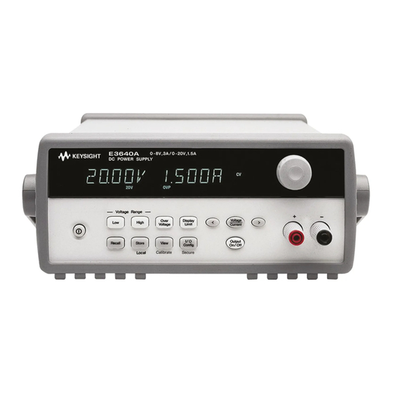
Page 40: Product At A Glance
Getting Started Product at a glance Front panel Figure 1-3 Front panel outlook Keysight E364xA User’s and Service Guide... -
Page 41: Table 1-4 Front Panel Overview
Getting Started Table 1-4 Front panel overview No Item Description Low voltage range selection key Select the low voltage range and allow its full rated output to the output terminals. High voltage range selection key Select the high voltage range and allow its full rated output to the output terminals. -
Page 42: Figure 1-4 Voltage And Current Limit Settings
Getting Started Voltage and current limit settings You can set the voltage and current limit values from the front panel using the following method. Figure 1-4 Voltage and current limit settings 1 Select the desired voltage range using the voltage range selection keys after turning on the power supply. -
Page 43: Rear Panel
Getting Started Rear panel Figure 1-5 Rear panel outlook The supplier code of the C-Tick for the E3643A or E3645A is N10149. NOTE Keysight E364xA User’s and Service Guide... -
Page 44: Display Annunciators
Getting Started Table 1-5 Rear panel overview Description AC inlet Power-line fuse-holder assembly Power-line module RS-232 interface connector GPIB (IEEE-488) interface connector Rear output terminals Use the front panel key to: – Select the GPIB or RS-232 interface. – Set the GPIB address. –... -
Page 45: Table 1-6 Display Annunciators Overview
Getting Started Table 1-6 Display annunciators overview Item Description Adrs The power supply is addressed to listen or talk over a remote interface. The power supply is in the remote interface mode. Indicate that the low voltage range is selected. /35V Indicate that the high voltage range is selected. -
Page 46: Output Connections
Getting Started Output Connections Before attempting to connect wires to the rear output terminals, make sure CAUTION to turn off the power supply first to avoid damage to the circuits being connected. Front panel binding posts are available to connect load wires for bench operation and are paralleled with the rear panel (+) and (–) connections. -
Page 47: Voltage Drops
Getting Started To satisfy safety requirements, load wires must be heavy enough not to overheat NOTE when carrying the maximum short-circuit output current of the power supply. If there is more than one load, then any pair of load wires must be capable of safely carrying the full-rated current of the power supply. -
Page 48: Remote Voltage Sensing Connections
Getting Started Pulse loading In some applications, the load current varies periodically from a minimum to a maximum value. The constant current circuit limits the output current. Some peak loading exceeding the current limit can be obtained due to the output capacitor. To stay within the specifications for the output, the current limit should be set greater than the peak current expected or the supply may go into the CC mode or unregulated mode for brief periods. -
Page 49: Figure 1-7 Remote Voltage Sensing Connections
Getting Started Connect one end of the sensing lead shield to the chassis ground ( ) only. Opening a sensing lead causes the power supply’s output voltage to decrease at the load leads. Observe the polarity when connecting the sensing leads to the load. - Page 50 Getting Started Stability Using remote sensing under certain combinations of load lead lengths and large load capacitances may cause your application to form a filter, which becomes part of the voltage feedback loop. The extra phase shift created by this filter can degrade the power supply’s stability, resulting in poor transient response or loop instability.
-
Page 51: Multiple Loads
Getting Started Output noise Any noise picked up on the sense leads also appears at the output of the power supply and may adversely affect the voltage load regulation. Twist the sense leads to minimize external noise pickup and run them parallel and close to the load leads. -
Page 52: Operating The Power Supply
Getting Started Operating the Power Supply Cooling The power supply can operate at the rated specifications within the temperature range of 0 °C to 40 °C. A fan cools the power supply by drawing air through the sides and exhausting it out the back. Using a Keysight rack-mount will not impede the flow of air. -
Page 53: Operation And Features
Keysight E364xA Single Output DC Power Supplies User’s and Service Guide Operation and Features Overview Constant Voltage Operation Constant Current Operation Configuring the Remote Interface Storing and Recalling Operating States Programming the Overvoltage Protection Disabling the Output System-Related Operations GPIB Interface Reference RS-232 Interface Reference Calibration This chapter describes the operations and features for the E364xA single output... -
Page 54: Overview
Operation and Features Overview The following section provides an overview of the front panel keys before operating your power supply. – The power supply is shipped from the factory configured in the front panel operation mode. At power-on, the power supply is automatically set to operate in the front panel operation mode. -
Page 55: Constant Voltage Operation
Operation and Features Constant Voltage Operation To set up the power supply for constant voltage (CV) operation, proceed as follows. Front panel operation 1 Connect a load to the output terminals With power-off, connect a load to the + and - output terminals. 2 Turn on the power supply. - Page 56 Operation and Features 4 Ad just the knob for the desired current limit. Check that the Limit annunciator still flashes. Set the knob for current control. The flashing digit can be changed using the resolution selection keys and the flashing digit can be adjusted by turning the knob. Adjust the knob to the desired current limit.
-
Page 57: Remote Interface Operation
Operation and Features Remote interface operation Set the current. CURRent {<current>|MIN|MAX} Set the voltage. VOLTage {<voltage>|MIN|MAX} Enable the output. OUTPut ON Keysight E364xA User’s and Service Guide... -
Page 58: Constant Current Operation
Operation and Features Constant Current Operation To set up the power supply for constant current (CC) operation, proceed as follows. Front panel operation 1 Connect a load to the output terminals. With power-off, connect a load to the + and – output terminals. 2 Turn on the power supply. - Page 59 Operation and Features 4 Ad just the knob for the desired voltage limit. Check that the Limit annunciator still flashes and the knob is selected for voltage control. The flashing digit can be changed using the resolution keys and the flashing digit can be adjusted by turning the knob. Adjust the knob for the desired voltage limit.
-
Page 60: Remote Interface Operation
Operation and Features Remote interface operation Set the voltage. VOLTage {<voltage>|MIN|MAX} Set the current. CURRent {<current>|MIN|MAX} Enable the output. OUTPut ON Keysight E364xA User’s and Service Guide... -
Page 61: Configuring The Remote Interface
Operation and Features Configuring the Remote Interface This power supply is shipped with both a GPIB (IEEE-488) interface and an RS-232 interface. The GPIB interface is selected when the power supply is shipped from the factory. Only one interface can be enabled at a time. To exit the I/O configuration mode without any changes, press until the NO CHANGE message is displayed. -
Page 62: Rs-232 Configuration
Operation and Features RS-232 configuration 1 Turn on the remote configuration mode. GPIB / 488 Notice that if you changed the remote interface selection to RS-232 before, the RS-232 message is displayed. 2 Choose the RS-232 interface. RS-232 You can choose the RS-232 interface by turning the knob. 3 Select the baud rate. -
Page 63: Storing And Recalling Operating States
Operation and Features Storing and Recalling Operating States You can store up to five different operating states in non-volatile storage locations. When shipped from the factory, storage locations 1 through 5 are empty. You can name a location from the front panel or over the remote interface but you can only recall a named state from the front panel. -
Page 64: Remote Interface Operation
Operation and Features 4 Save the operating state. DONE Recalling a stored state 1 Turn on the recall mode. Memory location 1 will be displayed in the recall mode. 1: P15V_TEST 2 Select the stored operating state. 2:STATE2 RESET You can select the above RESET mode to reset the power supply to the power-on state without turning power off/on or without using the *RST command over the remote interface. -
Page 65: Programming The Overvoltage Protection
Operation and Features Programming the Overvoltage Protection Overvoltage protection guards the load against output voltages reaching values greater than the programmed protection level. It is accomplished by shorting the output via an internal SCR when the trip level is set to equal or greater than 3 V, or by programming the output to 1 V when the trip level is set to less than 3 V. - Page 66 Operation and Features Checking the OVP operation To check the OVP operation, raise the output voltage to near the trip point. Then very gradually increase the output by turning the knob until the OVP circuit trips. This will cause the power supply output to drop to near zero, the OVP annunciator to flash, and the CC annunciator to turn on.
-
Page 67: Remote Interface Operation
Operation and Features – By adjusting the OVP trip level 1 Raise the OVP trip level higher than the level tripped 2 Select the OVP Clear mode by turning the knob. OVP ON OVP CLEAR 3 Clear the overvoltage cond ition and exit this menu. DONE The OVP annunciator will not flash any more. -
Page 68: Figure 2-1 Recommended Protection Circuit For Battery Charging
Operation and Features Figure 2-1 Recommended protection circuit for battery charging When the E364xA is powered up or down, the output voltage will overshoot to not more than ±1 V (i.e., +1 V max during power up and –1 V max during power down). -
Page 69: Figure 2-2 Recommended Connection To Prevent Voltage Overshoot
Operation and Features Figure 2-2 Recommended connection to prevent voltage overshoot Note the following considerations for the diode(s) selection: – The DUT’s input voltage should consider the voltage drop across the diode. The typical threshold voltage of a silicon diode is 0.6 V to 0.7 V. –... -
Page 70: Disabling The Output
Operation and Features Disabling the Output The output of the power supply can be disabled or enabled from the front panel. – When the power supply is in the Off state, the OFF annunciator turns on and the output is disabled. The OFF annunciator turns off when the power supply returns to the On state. -
Page 71: Disconnecting The Output Using An External Relay
Operation and Features Disconnecting the output using an external relay To disconnect the output, an external relay must be connected between the output and the load. A TTL signal of either low true or high true is provided to control an external relay. This signal can only be controlled with the remote command OUTPut:RELay {OFF|ON}. -
Page 72: System-Related Operations
Operation and Features System-Related Operations This section gives information on system-related topics such as storing power supply states, reading errors, running a self-test, displaying messages on the front panel, and reading firmware revisions. State storage The power supply has five storage locations in non-volatile memory to store power supply states. -
Page 73: Self-Test
Operation and Features Front panel operation STORE STATE, NAME STATE, EXIT To reset the power supply to the power-on reset state without using the *RST command or turning power off/on, select RESET from the following. 5 states, RESET, EXIT Remote interface operation Use the following commands to store and recall power supply states. -
Page 74: Error Conditions
Operation and Features Front panel operation To perform the complete front panel self-test, hold down as you turn on the power supply and hold down the key until you hear a long beep. The self-test will begin when you release the key following the beep. Remote interface operation *TST? Returns 0 if the complete self-test passes or 1 if it fails. -
Page 75: Scpi Language Version
Remote interface operation *IDN? The above command returns a string in the form of: “Keysight Technologies,E3640A,0,X.X-Y.Y-Z.Z” (E3640A) SCPI language version This power supply complies with the rules and regulations of the present version of Standard Commands for Programmable Instruments (SCPI). You can determine the SCPI version with which the power supply is in compliance by sending a command from the remote interface. -
Page 76: Gpib Interface Reference
Operation and Features GPIB Interface Reference The GPIB connector on the rear panel connects your power supply to the computer and other GPIB devices. Chapter 1, "Accessories" lists the cables that are available from Keysight. A GPIB system can be connected together in any configuration (star, linear, or both) as long as the following rules are observed: Each device on the GPIB (IEEE-488) interface must have a unique address. -
Page 77: Rs-232 Interface Reference
Operation and Features RS-232 Interface Reference The power supply can be connected to the RS-232 interface using the 9-pin (DB-9) serial connector on the rear panel. The power supply is configured as a Data Terminal Equipment (DTE) device. For all communications over the RS-232 interface, the power supply uses two handshake lines: Data Terminal Ready (DTR, on pin 4) and Data Set Ready (DSR, on pin 6). -
Page 78: Connection To A Computer Or Terminal
Operation and Features Connection to a computer or terminal To connect the power supply to a computer or terminal, you must have the proper interface cable. Most computers and terminals are Data Terminal Equipment (DTE) devices. Since the power supply is also a DTE device, you must use a DTE-to-DTE interface cable. -
Page 79: Rs-232 Trouble Shooting
Operation and Features DB-25 serial connection If your computer or terminal has a 25-pin serial port with a male connector, use the null-modem cable and 25-pin adapter included with the Keysight 34398A Cable Kit. The cable and adapter pin diagrams are as shown in Figure 2-4. -
Page 80: Calibration
Operation and Features Calibration This section gives an overview of the calibration features of the power supply. For more detailed discussion of the calibration procedures, refer to Chapter 8, "Service and Maintenance". Calibration security This feature allows you to enter a security code to prevent accidental or unauthorized calibrations of the power supply. -
Page 81: To Unsecure For Calibration
Operation and Features Table 2-1 Factory-setting security codes Model Security code E3640A 003640 E3641A 003641 E3642A 003642 E3643A 003643 E3644A 003644 E3645A 003645 To unsecure for calibration You can unsecure the power supply either from the front panel or over the remote interface. -
Page 82: To Secure Against Calibration
Operation and Features 3 Save the change and exit the menu. UNSECURED You will see the above message if the security code is correct, and the CAL MODE message is displayed. To exit the calibration mode, turn the power off and on. - Page 83 Operation and Features Front panel operation 1 Select the calibration mode. UNSECURED If the power supply is unsecured, the above message is displayed as you turn on the power supply by holding down the (Calibrate) key. Hold down the key until you hear a long beep and the CAL MODE message is displayed. 2 Enter the security code.
-
Page 84: To Change The Security Code
Operation and Features To change the security code To change the security code, you must first unsecure the power supply, and then enter a new code. Read the security code rules at “Calibration security” page 82 before attempting to secure the power supply. Front panel operation To change the security code, first make sure that the power supply is unsecured. -
Page 85: Calibration Count
Operation and Features Calibration count You can determine the number of times that your power supply has been calibrated. Your power supply was calibrated before it left the factory. When you receive your power supply, read the count to determine its initial value. The calibration count feature can be performed from the remote interface only. - Page 86 Operation and Features Front panel operation To read the calibration message from the front panel, press and turn the knob until CAL STRING is displayed. Press to scroll through the text of the message. Press to increase the scrolling speed. CAL STRING Remote interface operation To store the calibration message, send the following command.
-
Page 87: Remote Interface Reference
Keysight E364xA Single Output DC Power Supplies User’s and Service Guide Remote Interface Reference SCPI Command Summary Introduction to the SCPI Language Simplified Programming Overview Using the APPLy Command Output Setting and Operation Commands Triggering System-Related Commands State Storage Commands Calibration Commands Interface Configuration Commands SCPI Status Registers... -
Page 88: Scpi Command Summary
Remote Interface Reference SCPI Command Summary If you are a first-time user of the SCPI language, refer to Introduction to the SCPI NOTE Language Simplified Programming Overview to familiarize with the SCPI language before attempting to program the power supply. This section summarizes the SCPI (Standard Commands for Programmable Instruments) commands available to program the power supply over the remote interface. -
Page 89: Output Setting And Measurement Commands
Remote Interface Reference Output setting and measurement commands APPLy {<voltage>|DEF|MIN|MAX}[,{<current>|DEF|MIN|MAX}] APPLy? [SOURce:] CURRent[:LEVel][:IMMediate][:AMPLitude] {<current>|MIN|MAX|UP|DOWN} CURRent[:LEVel][:IMMediate][:AMPLitude]? [MIN|MAX] CURRent[:LEVel][:IMMediate]:STEP[:INCRement] {<numeric value> |DEFault} CURRent[:LEVel][:IMMediate]:STEP[:INCRement]? {DEFault} CURRent[:LEVel]:TRIGgered[:AMPLitude] {<current>|MIN|MAX} CURRent[:LEVel]:TRIGgered[:AMPLitude]? [MIN|MAX] VOLTage[:LEVel][:IMMediate][:AMPLitude] {<voltage>|MIN|MAX|UP|DOWN} VOLTage[:LEVel][:IMMediate][:AMPLitude]? [MIN|MAX] VOLTage[:LEVel][:IMMediate]:STEP[:INCRement] {<numeric value>|DEFault} VOLTage[:LEVel][:IMMediate]:STEP[:INCRement]? {DEFault} VOLTage[:LEVel]:TRIGgered[:AMPLitude] {<voltage>|MIN|MAX} VOLTage[:LEVel]:TRIGgered[:AMPLitude]? [MIN|MAX] VOLTage:PROTection[:LEVel] {<voltage>|MIN|MAX} VOLTage:PROTection[:LEVel]? {MIN|MAX} VOLTage:PROTection:STATe {0|1|OFF|ON} VOLTage:PROTection:STATe? -
Page 90: Triggering Commands
Remote Interface Reference Triggering commands INITiate[:IMMediate] TRIGger[:SEQuence] :DELay {<seconds>|MIN|MAX} :DELay? :SOURce {BUS|IMM} :SOURce? *TRG System-related commands DISPlay[:WINDow] [:STATe] {OFF|ON} [:STATe]? :TEXT[:DATA] <quoted string> :TEXT[:DATA]? :TEXT:CLEar SYSTem :BEEPer[:IMMediate] :ERRor? :VERSion? :COMMunicate:GPIB:RDEVice:ADDRess <numeric value> :COMMunicate:GPIB:RDEVice:ADDRess? OUTPut :RELay[:STATe] {OFF|ON} :RELay[:STATe]? [:STATe] {OFF|ON} [:STATe]? *IDN? *RST *TST? -
Page 91: State Storage Commands
Remote Interface Reference State storage commands *SAV {1|2|3|4|5} *RCL {1|2|3|4|5} MEMory:STATe :NAME {1|2|3|4|5}, <quoted name> :NAME? {1|2|3|4|5} Calibration commands CALibration :COUNt? :CURRent[:DATA] <numeric value> :CURRent:LEVel {MIN|MID|MAX} :SECure:CODE <new code> :SECure:STATe {OFF|ON},<code> :SECure:STATe? :STRing <quoted string> :STRing? :VOLTage[:DATA] <numeric value> :VOLTage:LEVel {MIN|MID|MAX} :VOLTage:PROTection Interface configuration commands SYSTem... -
Page 92: Status Reporting Commands
Remote Interface Reference Status reporting commands STATus:QUEStionable :CONDition? [:EVENt]? :ENABle <enable value> :ENABle? SYSTem:ERRor? *CLS *ESE <enable value> *ESE? *ESR? *OPC *OPC? *PSC {0|1} *PSC? *SRE <enable value> *SRE? *STB? *WAI Keysight E364xA User’s and Service Guide... -
Page 93: Ieee-488.2 Common Commands
Remote Interface Reference IEEE-488.2 common commands *CLS *ESR? *ESE <enable value> *ESE? *IDN? *OPC *OPC? *PSC {0|1} *PSC? *RST *SAV {1|2|3} *RCL {1|2|3} *STB? *SRE <enable value> *SRE? *TRG *TST? *WAI Keysight E364xA User’s and Service Guide... -
Page 94: Introduction To The Scpi Language
Remote Interface Reference Introduction to the SCPI Language SCPI (Standard Commands for Programmable Instruments) is an ASCII-based instrument command language designed for test and measurement instruments. Refer to Simplified Programming Overview for an introduction to the basic techniques used to program the power supply over the remote interface. SCPI commands are based on a hierarchical structure, also known as a tree system. -
Page 95: Command Format Used In This Manual
Remote Interface Reference Command format used in this manual The format used to show commands in this manual is shown below: CURRent {<current>|MINimum|MAXimum|UP|DOWN} The command syntax shows most commands (and some parameters) as a mixture of upper- and lower-case letters. The upper-case letters indicate the abbreviated spelling for the command. -
Page 96: Command Separators
Remote Interface Reference Command separators A colon ( : ) is used to separate a command keyword from a lower-level keyword as shown below: “SOURce:CURRent:TRIGgered” A semicolon ( ; ) is used to separate two commands within the same subsystem, and can also minimize typing. -
Page 97: Querying Parameter Settings
Remote Interface Reference Querying parameter settings You can query the value of most parameters by adding a question mark (?) to the command. For example, the following command sets the output current to 5 A: “CURR 5” You can query the value by executing: “CURR?”... -
Page 98: Ieee-488.2 Common Commands
Remote Interface Reference IEEE-488.2 common commands The IEEE-488.2 standard defines a set of common commands that perform functions like reset, self-test, and status operations. Common commands always begin with an asterisk ( * ), are four to five characters in length, and may include one or more parameters. - Page 99 Remote Interface Reference Boolean parameters Boolean parameters represent a single binary condition that is either true or false. For a false condition, the power supply will accept “OFF” or “0”. For a true condition, the power supply will accept “ON” or “1”. When you query a boolean setting, the power supply will always return “0”...
-
Page 100: Simplified Programming Overview
Remote Interface Reference Simplified Programming Overview This section gives an overview of the basic techniques used to program the power supply over the remote interface. This section is only an overview and does not give all of the details you will need to write your own application programs. Refer to the remainder of this chapter and also Chapter 5, "Application Programs", for... -
Page 101: Reading A Query Response
Remote Interface Reference Reading a query response Only the query commands (commands that end with “?”) will instruct the power supply to send a response message. Queries return either output values or internal instrument settings. For example, the following statements executed from your computer will read the power supply’s error queue and print the most recent error: Dimension string array (80 elements) -
Page 102: Power Supply Programming Ranges
Remote Interface Reference Power supply programming ranges The SOURce subsystem requires parameters for programming values. The available programming value for a parameter varies according to the desired output range of the power supply. Table 3-1 lists the programming values available and MINimum, MAXimum, DEFault and reset values of your power supplies. - Page 103 Remote Interface Reference Table 3-2 Keysight E3641A/E3643A/E3645A programming ranges E3641A E3643A E3645A 0 to 35V /0.8 A 0 to 60 V/0.5 A 0 to 35 V/1.4 A 0 to 60 V/0.8 A 0 to 35 V/2.2 A 0 to 60 V/1.3 A range range range...
-
Page 104: Using The Apply Command
Remote Interface Reference Using the APPLy Command The APPLy command provides the most straightforward method to program the power supply over the remote interface. You can select the output voltage and current in one command. APPLy {<voltage>| DEF|MIN|MAX}[,{<current>| DEF|MIN|MAX}] This command is combination of VOLTage and CURRent commands. The APPLy command changes the power supply’s output to the newly programmed values only if the programmed values are valid within the presently selected range. -
Page 105: Output Setting And Operation Commands
Remote Interface Reference Output Setting and Operation Commands This section describes low-level commands used to program the power supply. Although the APPLy command provides the most straightforward method to program the power supply, the low-level output setting commands give you more flexibility to change the individual parameters. - Page 106 Remote Interface Reference The CURR:STEP? DEF returns the minimum resolution of your instrument. The immediate current level increases or decreases by the value of the step size. For example, the output current will increase or decrease 10 mA if the step size is 0.01.
- Page 107 Remote Interface Reference VOLTage {<voltage>| MINimum|MAXimum|UP|DOWN} Program the immediate voltage level of the power supply. The immediate level is the voltage value of the output terminals. The VOLTage command changes the output of the power supply to the newly programmed value regardless of the output range presently selected. This command also increases or decreases the immediate voltage level using the UP or DOWN parameter by a predetermined amount.
- Page 108 Remote Interface Reference Example The following program segments show how to use the VOLT UP or VOLT DOWN command to increase or decrease the output voltage with the VOLT:STEP command. Set the step size to 0.01 V VOLT:STEP 0.01 Increase the output voltage VOLT UP Set the step size to 0.02 V VOLT:STEP 0.02...
- Page 109 Remote Interface Reference VOLTage:PROTection:STATe? Query the state of the overvoltage protection function. The returned parameter is “0” (OFF) or “1” (ON). VOLTage:PROTection:TRIPped? Return a “1” if the overvoltage protection circuit is tripped and not cleared or a “0” if not tripped. VOLTage:PROTection:CLEar Cause the overvoltage protection circuit to be cleared.
-
Page 110: Triggering
– You can also trigger the power supply from the GPIB interface by sending the IEEE-488 Group Execute Trigger (GET) message. The following statement shows how to send a GET from a Keysight Technologies controller. (group execute trigger) TRIGGER 705... - Page 111 Remote Interface Reference – To ensure synchronization when the bus source is selected, send the *WAI (wait) command. When the *WAI command is executed, the power supply waits for all pending operations to complete before executing any additional commands. For example, the following command string guarantees that the first trigger is accepted and is executed before the second trigger is recognized.
-
Page 112: Triggering Commands
Remote Interface Reference Triggering commands INITiate This command causes the trigger system to initiate. This command completes one full trigger cycle when the trigger source is an immediate and initiates the trigger subsystem when the trigger source is bus. TRIGger:DELay {<seconds>| MINimum|MAXimum} This command sets the time delay between the detection of an event on the specified trigger source and the start of any corresponding trigger action on the power supply output. -
Page 113: System-Related Commands
Remote Interface Reference System-Related Commands DISPlay {OFF|ON} Turn the front-panel display off or on. When the display is turned off, outputs are not sent to the display and all annunciators are disabled except the ERROR annunciator. The display state is automatically turned on when you return to the local mode. - Page 114 Remote Interface Reference OUTPut:RELay {OFF|ON} Sets the state of two TTL signals on the RS-232 connector. These signals are intended for use with an external relay and relay driver. At RST, the OUTPut:RELay state is OFF. Refer to “Disconnecting the output using an external relay”...
- Page 115 The command returns a string with the following format (be sure to dimension a string variable with at least 40 characters): (E3640A model) Keysight Technologies,E3640A,0,X.X-Y.Y-Z.Z *TST? Performs a complete self-test of the power supply. Returns “0” if the self-test passes or “1” or any non-zero value if it fails. If the self-test fails, an error message is also generated with additional information on why the test failed.
-
Page 116: Table 3-3 Reset State Of The Power Supply
Remote Interface Reference Table 3-3 Reset state of the power supply Command E3640A E3641A E3642A E3643A E3644A E3645A state state state state state state CURR 0.8 A 1.4 A 2.2 A CURR:STEP 0.052 mA 0.015 mA 0.095 mA 0.026 mA 0.152 mA 0.042 mA CURR:TRIG... -
Page 117: State Storage Commands
Remote Interface Reference State Storage Commands The power supply has five storage locations in non- volatile memory to store power supply states. The locations are numbered 1 through 5. You can also assign a name to each of the locations (1 through 5) for use from the front panel. *SAV {1|2|3|4|5} Store (Save) the present state of the power supply to the specified location. - Page 118 Remote Interface Reference MEMory:STATe:NAME {1|2|3|4|5}, <quoted name> MEMory:STATe:NAME? {1|2|3|4|5} Assign a name to the specified storage location. From the remote interface, you can only recall a stored state using a number (1 through 5). The :NAME? query returns a quoted string containing the name currently assigned to the specified storage location.
-
Page 119: Calibration Commands
Remote Interface Reference Calibration Commands Refer to “Calibration” on page 82 for an overview of the calibration features of the power supply. An example program for calibration is listed in “Calibration example” on page 123. For more detailed information on the calibration procedures, refer to the Chapter 8, "Service and Maintenance". - Page 120 Remote Interface Reference CALibration:SECure:CODE <quoted new code> This command enters a new security code. To change the security code, first unsecure the power supply using the old security code. Then, enter the new code. The calibration code may contain up to 11 characters over the remote interface.
-
Page 121: Calibration Example
Remote Interface Reference CALibration:VOLTage:LEVel {MINimum|MIDdle|MAXimum} This command can only be used after calibration is unsecured and the output state is ON. It sets the power supply to a calibration point that is entered with CAL:VOLT command. During calibration, three points must be entered and the low-end point (MIN) must be selected and entered first. - Page 122 Remote Interface Reference 7 Set the power supply to the middle (MID) calibration point. CAL:VOLT:LEV MID 8 Enter the reading you obtained from the DVM. CAL:VOLT:DATA 11.058 9 Set the power supply to the high (MAX) calibration point. CAL:VOLT:LEV MAX 10 Enter the reading you obtained from the DVM.
-
Page 123: Interface Configuration Commands
Remote Interface Reference Interface Configuration Commands See also Chapter 2, "Configuring the Remote Interface" for more information. SYSTem:INTerface {GPIB|RS232} Select the remote interface. Only one interface can be enabled at a time. The GPIB interface is selected when the power supply is shipped from the factory. SYSTem:LOCal This command places the power supply in the local mode during RS-232 operation. -
Page 124: Scpi Status Registers
Remote Interface Reference SCPI Status Registers All SCPI instruments implement status registers in the same way. The status system records various instrument conditions in three register groups: the Status Byte register, the Standard Event register, and the Questionable Status register groups. -
Page 125: Figure 3-1 Scpi Status System
Remote Interface Reference Figure 3-1 SCPI status system Keysight E364xA User’s and Service Guide... -
Page 126: Questionable Status Register
Remote Interface Reference Questionable status register The Questionable Status register provides information about voltage and current regulation. Bit 0 is set when the voltage becomes unregulated, and bit 1 is set if the current becomes unregulated. For example if the power supply momentarily goes to constant current mode when the power supply is operating as a voltage source (constant voltage mode), bit 0 is set to indicate that the voltage output is not regulated. -
Page 127: Standard Event Register
Remote Interface Reference Standard event register The Standard Event register reports the following types of instrument events: power on detected, command syntax errors, command execution errors, self-test or calibration errors, query errors, or when an *OPC command is executed. Any or all of these conditions can be reported in the standard event summary bit (ESB, bit 5) of Status Byte register through the enable register. -
Page 128: Status Byte Register
Remote Interface Reference The standard event register is cleared when: – You execute the *CLS (clear status) command. – You query the event register using the *ESR? (Event Status register) command. For example, 28 (4 + 8 + 16) is returned when you have queried the status of the Standard Event register, QYE, DDE, and EXE conditions have occurred. -
Page 129: Using Service Request (Srq) And Serial Poll
Remote Interface Reference The status byte summary register is cleared when: – you execute the *CLS (clear status) command. – Querying the Standard Event register (*ESR? command) will clear only bit 5 in the Status Byte summary register. For example, 24 (8 + 16) is returned when you have queried the status of the Status Byte register, QUES and MAV conditions have occurred. -
Page 130: Using *Stb? To Read The Status Byte
Remote Interface Reference The IEEE-488 standard does not ensure synchronization between your bus NOTE controller program and the instrument. Use the *OPC? command to guarantee that commands previously sent to the instrument have completed. Executing a serial poll before a *RST, *CLS, or other commands have completed can cause previous conditions to be reported. -
Page 131: Determining When A Command Sequence Is Completed
Remote Interface Reference Determining when a command sequence is completed 1 Send a device clear message to clear the power supply’s output buffer (for example, CLEAR 705). 2 Clear the event registers with the *CLS (clear status) command. 3 Enable the “operation complete” bit (bit 0) in the Standard Event register by executing the *ESE 1 command. -
Page 132: Status Reporting Commands
Remote Interface Reference Status Reporting Commands Refer to Figure 3-1 for detailed information of the status register structure of the power supply. SYSTem:ERRor? Query the power supply’s error queue. A record of up to 20 errors is stored in the power supply’s error queue. Errors are retrieved in the first- in- first- out (FIFO) order. - Page 133 Remote Interface Reference *ESE<enable value> Enable bits in the Standard Event enable register. The selected bits are then reported to the Status Byte. *ESE? Query the Standard Event enable register. The power supply returns a decimal value which corresponds to the binary-weighted sum of all bits in the register. *ESR? Query the Standard event register.
- Page 134 Remote Interface Reference *STB? Query the Status Byte summary register. The *STB? command is similar to a serial poll but it is processed like any other instrument commands. The *STB? command returns the same result as a serial poll but the “Request Service”...
-
Page 135: Halting An Output In Progress
Remote Interface Reference Halting an Output in Progress You can send a device clear at any time to stop an output in progress over the GPIB interface. The status registers, the error queue, and all configuration states are left unchanged when a device clear message is received. Device clear performs the following actions. -
Page 136: Scpi Conformance Information
Remote Interface Reference SCPI Conformance Information The power supply conforms to the ‘1997.0’ version of the SCPI standard. Many of the commands required by the standard are accepted by the power supply but are not described in this manual for simplicity or clarity. Most of these non- documented commands duplicate the functionality of a command already described in this manual. - Page 137 Remote Interface Reference [SOURce] :VOLTage[:LEVel][:IMMediate][:AMPLitude] {<voltage>|MIN|MAX|UP|DOWN} :VOLTage[:LEVel][:IMMediate][:AMPLitude]?[MIN|MAX] :VOLTage[:LEVel][:IMMediate]:STEP[:INCRement] {<numeric value>|DEFault} :VOLTage[:LEVel][:IMMediate]:STEP[:INCRement]? {DEFault} :VOLTage[:LEVel]:TRIGgered[:AMPLitude] {<voltage>|MIN|MAX} :VOLTage[:LEVel]:TRIGgered[:AMPLitude]?[MIN|MAX] :VOLTage:PROTection[:LEVel] {<voltage>|MIN|MAX} :VOLTage:PROTection[:LEVel]? {MIN|MAX} :VOLTage:PROTection:STATe {0|1|OFF|ON} :VOLTage:PROTection:STATe? :VOLTage:PROTection:TRIPped? :VOLTage:PROTection:CLEar :VOLTage:RANGe {P8V |P20V |P35V |P60V |LOW|HIGH} :VOLTage:RANGe? STATus :QUEStionable:CONDition? :QUEStionable[:EVENt]? :QUEStionable:ENABle <enable value> :QUEStionable:ENABle? SYSTem :BEEPer[:IMMediate] :ERRor? :VERSion TRIGger...
-
Page 138: Device Specific Commands
Remote Interface Reference Device specific commands The following commands are device- specific to your power supply. They are not included in the ‘1997.0’ version of the SCPI standard. However, these commands are designed with the SCPI standard in mind, and they follow all of the command syntax rules defined by the standard. -
Page 139: Ieee-488 Conformance Information
Remote Interface Reference IEEE-488 Conformance Information Ded icated Hard ware Lines IEEE488 Common Commands Attention *CLS Interface Clear *ESE <enable value> Remote Enable *ESE? Service Request Enable *ESR? *IDN? Addressed Commands *OPC *OPC? Device Clear *PSC {0|1} End or Identify *PSC? Group Execute Trigger *RST... - Page 140 Remote Interface Reference THIS PAGE HAS BEEN INTENTIONALLY LEFT BLANK. Keysight E364xA User’s and Service Guide...
-
Page 141: Error Messages
E364xA Single Output DC Power Supplies User’s and Service Guide Error Messages Overview Execution Error Messages Self-Test Error Messages Calibration Error Messages This chapter lists the error messages that may appear as you are working with the power supply. -
Page 142: Overview
Error Messages Overview Errors are retrieved in first-in-first-out (FIFO) order. The first error returned is the first error that was stored. Errors are cleared as you read them over the remote interface. When you have read all errors from the queue, the ERROR annunciator turns off and the errors are cleared. -
Page 143: Remote Interface Operation
Error Messages Remote interface operation Read and clear one error from the error queue SYSTem:ERRor? Errors have the following format (the error string may contain up to 80 characters). -102, “Syntax error” E364xA User’s and Service Guide... -
Page 144: Execution Error Messages
Error Messages Execution Error Messages Table 4-1 Execution error messages Invalid character -101 An invalid character was found in the command string. You may have inserted a character such as #, $, or % in the command keyword or within a parameter. Example: OUTP:STAT #ON Syntax error -102... - Page 145 Error Messages Table 4-1 Execution error messages Missing parameter -109 Fewer parameters were received than expected for the command. You omitted one or more parameters that are required for this command. Example: APPL Program mnemonic too long -112 A command header was received which contained more than the maximum 12 characters allowed.
- Page 146 Error Messages Table 4-1 Execution error messages Numeric data not allowed -128 A numeric parameter was received but a character string was expected. Example: DISP:TEXT 123 Suffix error -130 A suffix was incorrectly specified for a numeric parameter. You may have misspelled the suffix or the numeric parameter does not accept a suffix.
- Page 147 Error Messages Table 4-1 Execution error messages Invalid string data -151 An invalid character string was received. Check to see if you have enclosed the character string in single or double quotes. Example: DISP:TEXT ’ON String data not allowed -158 A character string was received but is not allowed for the command.
- Page 148 Error Messages Table 4-1 Execution error messages Too much data -223 A character string was received but could not be executed because the string length was more than 40 characters. This error can be generated by the CALibration:STRing command. Illegal parameter value -224 A discrete parameter was received which was not a valid choice for the command.
- Page 149 Error Messages Table 4-1 Execution error messages Query DEADLOCKED -430 A command was received which generates too much data to fit in the output buffer and the input buffer is also full. Command execution continues but all data is lost. Query UNTERMINATED after indefinite response -440 The *IDN? command must be the last query command within a command string.
-
Page 150: Self-Test Error Messages
Error Messages Self-Test Error Messages The following errors indicate failures that may occur during a self- test. Refer to Chapter 8, "Service and Maintenance" for more information. Table 4-2 Self-test error messages Front panel does not respond The main controller U121 (U10 for serial MY53xx6xxx) attempts to establish serial communications with the front panel controller U1 (U602 for serial MY53xx6xxx) on the front panel board. - Page 151 Error Messages Table 4-2 Self-test error messages Rundown gain out of range This test checks the nominal gain between the integrating ADC and the U121 on-chip ADC. The nominal gain is checked to a ±10% tolerance. Rundown too noisy This test checks the gain repeatability between the integrating ADC and the U121 on-chip ADC.
- Page 152 Error Messages Table 4-2 Self-test error messages Fan test failed This test checks if the fan current is flowing. If the current is not detected at the power-on self-test, the power supply will beep and the error annunciator will be turned on.
-
Page 153: Calibration Error Messages
Error Messages Calibration Error Messages The following errors indicate failures that may occur during a calibration. Refer to the Service Guide for more information. Table 4-3 Calibration error messages Cal security disabled by jumper The calibration security feature has been disabled with a jumper inside the power supply. - Page 154 Error Messages Table 4-3 Calibration error messages Bad DAC cal data The specified DAC calibration values (CAL:VOLT or CAL:CURR) are out of range. Note that the new calibration constants are not stored in the non-volatile memory. Bad readback cal data The specified readback calibration values (CAL:VOLT or CAL:CURR) are out of range.
- Page 155 Error Messages Table 4-3 Calibration error messages Cal checksum failed, store/recall data in location 4 Cal checksum failed, store/recall data in location 5 E364xA User’s and Service Guide...
- Page 156 Error Messages THIS PAGE HAS BEEN INTENTIONALLY LEFT BLANK. E364xA User’s and Service Guide...
-
Page 157: Application Programs
E364xA Single Output DC Power Supplies User’s and Service Guide Application Programs Overview Example Program for C and C++ Example Program for Excel 97 This chapter contains two application programs that utilize the remote interface. -
Page 158: Overview
Application Programs Overview The application program examples in this chapter help you to develop programs for your own application. Chapter 3, "Remote Interface Reference" lists the syntax for the SCPI commands available to program the power supply. The examples in this chapter have been tested on a PC running Windows 3.1, Windows 95, or Windows NT 4.0. -
Page 159: Example Program For C And C
Application Programs Example Program for C and C++ The following C programming example shows you how to send and receive formatted I/O. This example programming shows you how to use the SCPI commands for the instrument with the VISA functionality and does include error trapping. - Page 160 Application Programs void main() double voltage; /* Value of voltage sent to power supply char Buffer[256]; /* String returned from power supply double current; /* Value of current output of power supply OpenPort(); /* Query the power supply id, read response and print it */ sprintf(Buffer,"*IDN?");...
- Page 161 Application Programs void OpenPort() char GPIB_Address[3]; char COM_Address[2]; char VISA_address[40]; /* Complete VISA address sent to card */ if(bGPIB) strcpy(GPIB_Address,"5"); /* Select GPIB address between 0 to 30*/ else strcpy(COM_Address,"1"); /* Set the number to 2 for COM2 port */ if(bGPIB) /* For use with GPIB 7 address, use "GPIB::7::INSTR"...
- Page 162 Application Programs void ClosePort() /* Close the communication port */ viClose(power_supply); viClose(defaultRM); void CheckError(char* pMessage) if (ErrorStatus VI_SUCCESS) printf("\n %s",pMessage); ClosePort(); exit(0); void delay(clock_t wait) clock_t goal; goal = wait + clock(); while( goal > clock() ) ; End of program E364xA User’s and Service Guide...
-
Page 163: Example Program For Excel 97
Application Programs Example Program for Excel 97 This section contains the example program written using Excel Macros (Visual Basic® for Applications) to control your power supply. With Excel you can take the value of a cell in a spread sheet, send it to the power supply, and then record the response on the worksheet. - Page 164 Application Programs 5 To change the button name, click the right mouse button on that button and then select Properties. The Properties dialog box appears. 6 In the Properties dialog, change the (name) and caption to Diode. 7 To try the example for characterizing a diode, type Voltages in cell A4 and Current in cell B4.
- Page 165 Application Programs Diode Macro '"""""""""""""""""""""""""""""""""""""""""""""""""""""""""""""""""""""""""""""" ' This is the subroutine first executed. Modify this routine to suit ' your needs. To change the GPIB address, go to the module OpenPort, and ' change the variable GPIB_Address = "5” to the required GPIB address. ' To change the RS-232 port, go to the module OpenPort, and change the ' variable COM_Address = "1”...
- Page 166 Application Programs '****************************************************************************** ' This routine send a SCPI command string to the GPIB port or RS-232 port. ' If the command contains a question mark, the response is read, and returned '****************************************************************************** Private Function SendSCPI(command As String) As string Dim commandString As String ' Command passed to power supply Dim ReturnString As String...
-
Page 167: Declaration For Windows 3.1
Application Programs Declaration for Windows 3.1 '****************************************************************************** ' This routine requires the file VISA.dll. It typically resides in the ' c:\windows\system directory. Additional declations for VISA.DLL are usally in ' file visa.bas under c:\vxipnp\win31\include directory on your PC. This routine ' uses the VTL Library to send commands to an instrument. - Page 168 Application Programs THIS PAGE HAS BEEN INTENTIONALLY LEFT BLANK. E364xA User’s and Service Guide...
-
Page 169: Tutorial
E364xA Single Output DC Power Supplies User’s and Service Guide Tutorial Overview of the Power Supply Operation Output Characteristics Extending the Voltage and Current Range Remote Programming This chapter describes the basic operation of a linear power supply and the operation of this power supply. -
Page 170: Overview Of The Power Supply Operation
Tutorial Overview of the Power Supply Operation The basic design technique, which has not changed over the years, consists of placing a control element in series with the rectifier and load device. Figure 6-1 shows a simplified schematic of a series regulated supply with the phase-controlled pre-regulator described as a power switch and the series element depicted as a variable resistor. -
Page 171: Figure 6-2 Block Diagram Of The Power Supply Showing The Remote Interface Isolation
Tutorial In terms of performance, a linear regulated supply has a very precise regulating properties and responds quickly to variations of the line and load. Hence, its line and load regulation and transient recovery time are superior to supplies using other regulation techniques. -
Page 172: Output Characteristics
Tutorial Output Characteristics An ideal constant-voltage power supply would have a zero output impedance at all frequencies. Thus, as shown in Figure 6-3, the voltage would remain perfectly constant in spite of any changes in output current demanded by the load. Figure 6-3 Ideal constant voltage Figure 6-4... -
Page 173: Figure 6-5 Output Characteristics
Tutorial Figure 6-5 shows the operating modes of the output of the power supply. The operating point of one supply will be either above or below the line R . This line represents a load where the output voltage and the output current are equal to the voltage and current setting. -
Page 174: Unregulated State
Tutorial Unregulated state If the power supply should go into a mode of operation that is neither CV or CC, the power supply is unregulated. In this mode the output is not predictable. The unregulated condition may be the result of the ac line voltage below the specifications. -
Page 175: Figure 6-6 Simplified Diagram Of Common Mode And Normal Mode Sources Of Noise
Tutorial The output will also change due to changes in the load. As the load increases the output current will cause a small drop in the output voltage of the power supply due to the output impedance R. Any resistance in the connecting wire will add to this resistance and increase the voltage drop. -
Page 176: Extending The Voltage And Current Range
Tutorial Extending the Voltage and Current Range The power supply may be able to provide voltages and currents greater than its rated maximum outputs if the power-line voltage is at or above its nominal value. Operation can be extended up to 3% over the rated output without damage to the power supply, but performance cannot be guaranteed to meet specifications in this region. -
Page 177: Remote Programming
Tutorial Remote Programming During remote programming a constant-voltage regulated power supply is called upon to change its output voltage rapidly. The most important factor limiting the speed of output voltage change is the output capacitor and load resistor. Figure 6-7 Speed of response - programming up (full load) The equivalent circuit and the nature of the output voltage waveform when the supply is being programmed upward are shown in... -
Page 178: Figure 6-8 Speed Of Response - Programming Down
Tutorial If no load resistor is attached to the power supply output terminal, then the output voltage will rise linearly at a rate of C when programmed upward, and TR = , the shortest possible up-programming time. Figure 6-8 Speed of response - programming down Figure 6-8 shows that when the power supply is programmed down, the regulator senses that the output voltage is higher than desired and turns off the series... - Page 179 E364xA Single Output DC Power Supplies User’s and Service Guide Characteristic and Specifications Physical Characteristics Environmental Characteristics Electrical Specifications Supplemental Characteristics This chapter lists the characteristics and specifications of the E364xA single output DC power supplies. Specifications are warranted in the temperature range of 0 °C to 40 °C with a NOTE resistive load.
-
Page 180: Characteristic And Specifications
Characteristic and Specifications Physical Characteristics Table 7-1 Physical characteristics Parameters E3640A E3641A E3642A E3643A E3644A E3645A Dimensions (W x H x D) 212.6 mm × 88.5 mm × 348.3 mm Weight 5.3 kg 5.2 kg 6.3 kg 6.2 kg 6.6 kg 6.7 kg Shipping 7.2 kg... -
Page 181: Environmental Characteristics
Characteristic and Specifications Figure 7-2 E364xA dimensions for rack mounting Environmental Characteristics Refer to “Australia/New Zealand: AS/NZS CISPR11:2004” on page 6. E364xA User’s and Service Guide... -
Page 182: Electrical Specifications
Characteristic and Specifications Electrical Specifications Table 7-2 Electrical specifications Parameters E3640A E3641A E3642A E3643A E3644A E3645A Vol tage output (V) Low range 0 to +8 V 0 to +35 V 0 to +8 V 0 to +35 V 0 to +8 V 0 to +35 V (at 0 to 40 °C) High range... - Page 183 Characteristic and Specifications Table 7-2 Electrical specifications Line regulation Voltage <0.01% + 3 mV ±(% of output + offset) Current <0.01% + 250 µA Programming resolution Voltage <5 mV Current <1 mA Read back resolution Voltage <2 mV Current <1 mA Front panel resolution Voltage 10 mV...
-
Page 184: Supplemental Characteristics
Characteristic and Specifications Supplemental Characteristics Table 7-3 Supplemental characteristics Parameters E3640A E3641A E3642A E3643A E3644A E3645A Output Low range 0 to +8.24 V 0 to +36.05 V 0 to +8.24 V 0 to +36.05 V 0 to +8.24 V 0 to +36.05 V programming 0 to 3.09 A 0 to 0.824 A... - Page 185 Characteristic and Specifications Table 7-3 Supplemental characteristics Output terminal – ±60 Vdc when connecting shorting conductors without insulation between the (+) output and the (+) sense terminals and between the (–) output and the (–) sense isolation terminals. (maximum, from –...
- Page 186 Characteristic and Specifications THIS PAGE HAS BEEN INTENTIONALLY LEFT BLANK. E364xA User’s and Service Guide...
-
Page 187: Service And Maintenance
E364xA Single Output DC Power Supplies User’s and Service Guide Service and Maintenance Overview Operating Checklist Types of Services Available Repacking for Shipment Electrostatic Discharge (ESD) Precautions Surface Mount Repair Replacing the Power-Line Fuse Troubleshooting Hints Self-Test Procedures General Disassembly Recommended Test Equipment Test Considerations Operation Verification and Performance Tests... -
Page 188: Overview
Service and Maintenance Overview The power supply must pass the complete self-test before calibration or any of the verification or performance tests can be performed. If the power supply fails any of the tests or if abnormal test results are obtained, refer to “Troubleshooting Hints”... -
Page 189: Operating Checklist
Service and Maintenance – Calibration Error Messages Component drawings – Component Locator Diagram Operating Checklist Before returning your power supply to Keysight for service or repair, check the following items: Is the power supply inoperative? – Verify that the AC power cord is connected to the power supply. –... -
Page 190: Types Of Services Available
Service and Maintenance Types of Services Available If your power supply fails within three years of the original purchased date, Keysight will repair or replace it free of charge. If your unit fails after your three years warranty expires, Keysight will repair or replace it at a very competitive price. -
Page 191: Electrostatic Discharge (Esd) Precautions
Service and Maintenance Electrostatic Discharge (ESD) Precautions Almost all electrical components can be damaged by electrostatic discharge (ESD) during handling. Component damage can occur at electrostatic discharge voltages as low as 50 V. The following guidelines will help prevent ESD damage when servicing the power supply or any electronic device. -
Page 192: Troubleshooting Hints
Service and Maintenance Troubleshooting Hints This section provides a brief checklist of common failures. Before troubleshooting or repairing the power supply, make sure that the failure is in the power supply rather than any external connections. Also make sure that the power supply is accurately calibrated. -
Page 193: Table 8-1 Bias Supplies Voltages
Service and Maintenance Table 8-1 Bias supplies voltages Bias supply Minimum Maximum Check at +5 V floating +4.75 V +5.25 V U110 pin 2 –5.1 V floating –4.75 V -5.25 V Anode of CR114 +15 V floating +14.25 V +15.75 V Anode of CR104 –15 V floating -14.25 V... -
Page 194: Self-Test Procedures
Service and Maintenance Self-Test Procedures Power-on self test Each time the power supply is powered on, a set of self-tests are performed. These tests check that the minimum set of logic and measurement hardware are functioning properly. Failures during the power-on self-test utilize error codes 601 through 604 and 624 through 632. -
Page 195: Table 8-3 Self-Test Error Messages
Service and Maintenance Table 8-3 Self-test error messages Fan test failed System DAC test failed Hardware test failed [a] This error message is only applicable for serial MY53xx6xxx. E364xA User’s and Service Guide... -
Page 196: General Disassembly
Service and Maintenance General Disassembly E364xA User’s and Service Guide... -
Page 197: Recommended Test Equipment
Service and Maintenance Recommended Test Equipment Table 8-4 describes the test equipment recommended for the performance verification and adjustment procedures. If the exact equipment is not available, use the accuracy requirements shown to select substitute calibration standards. If you use equipment other than the recommended equipment shown in Table 8-4, you must recalculate the measurement uncertainties for the actual equipment... - Page 198 Service and Maintenance Table 8-4 Recommended test equipment Resistive loads (R – For E3640A: Measure ripple and noise 2.7 Ω,150 W/13.5 Ω,150 W – For E3641A: 43.8 Ω, 300 W/120 Ω, 300 W – For E3642A: 1.6 Ω, 300 W/8.0 Ω, 300 W –...
-
Page 199: Test Considerations
Service and Maintenance Test Considerations To ensure proper operation of the power supply, verify that you have selected the correct power-line voltage prior to attempting any test procedure in this chapter (refer to “Converting line voltage” on page 36). Ensure that all terminal connections (both front panel and rear panel) are removed while the internal self-test is being performed. -
Page 200: Operation Verification And Performance Tests
Service and Maintenance Operation Verification and Performance Tests Operation verification tests To ensure that the power supply is operating properly, without testing all specified parameters, perform the following verification tests: – Perform the power-on self-test and follow the procedures for “Checking the output”... -
Page 201: Measurement Techniques
Service and Maintenance Measurement Techniques Common test setup Most tests are performed at the front terminals as shown in Figure 8-1. Measure the DC voltage directly at the (+) and (-) terminals on the front panel. Figure 8-1 Performance verification test setup E364xA User’s and Service Guide... -
Page 202: Current-Monitoring Resistor
Service and Maintenance Current-monitoring resistor To eliminate the output current measurement error caused by the voltage drops in the leads and connections, connect the current-monitoring resistor between the (–) output terminal and the load as a four-terminal device. Connect the current-monitoring leads inside the load-lead connections directly at the monitoring points on the resistor element (refer to R Figure... -
Page 203: Electronic Load
Service and Maintenance Electronic load Many of the test procedures require the use of a variable load resistor capable of dissipating the required power. Using a variable load resistor requires that switches should be used to connect, disconnect, and short the load resistor. An electronic load, if available, can be used in place of a variable load resistor and switches. -
Page 204: Constant Voltage (Cv) Verifications
Service and Maintenance Constant Voltage (CV) Verifications Constant voltage test setup If more than one meter or if a meter and an oscilloscope are used, connect each to the (+) and (–) terminals by a separate pair of leads to avoid mutual coupling effects. - Page 205 Service and Maintenance 2 Turn on the power supply. Select the high voltage range (20 V/1.5 A) enable the output by sending the following commands: (E3640A model) VOLT:RANG P20V OUTP ON 3 Program the output voltage to 0 V and current to the full-scale rated value (1.5 by sending the following commands: VOLT 0 (E3640A model)
-
Page 206: Cv Load Effect (Load Regulation)
Service and Maintenance CV load effect (load regulation) This test measures the immediate change in the output voltage resulting from a change in the output current from full to no load. 1 Turn off the power supply and connect a digital voltmeter between the (+) and (–) terminals of the output as shown in Figure 8-1. -
Page 207: Cv Source Effect (Line Regulation)
Service and Maintenance CV source effect (line regulation) This test measures the immediate change in the output voltage that results from a change in the AC line voltage from the minimum value (10% below the nominal input voltage) to the maximum value (10% above the nominal input voltage). 1 Turn off the power supply and connect a digital voltmeter between the (+) and (–) terminals of the output to be tested as shown in Figure... -
Page 208: Cv Pard (Ripple And Noise)
Service and Maintenance CV PARD (ripple and noise) Periodic and random deviations (PARD) in the output (ripple and noise) combine to produce a residual AC voltage superimposed on the DC output voltage. CV PARD is specified as the rms or peak-to-peak output voltage in the frequency range from 20 Hz to 20 MHz. - Page 209 Service and Maintenance 1 Turn off the power supply and connect the output to be tested as shown in Figure 8-1 to an oscilloscope (AC-coupled) between the (+) and (–) terminals. Set the oscilloscope to the AC mode and bandwidth limit of 20 MHz. Connect a resistive load (13.5 Ω) to the terminal at (B) as shown in Figure...
-
Page 210: Load Transient Response Time
Service and Maintenance Load transient response time This test measures the time for the output voltage to recover to within 15 mV of the nominal output voltage following a load change from full load to half load, or half load to full load. 1 Turn off the power supply and connect the output to be tested as shown in Table 8-1 with an oscilloscope. -
Page 211: Constant Current (Cc) Verification
Service and Maintenance Constant Current (CC) Verification Constant current test setup Follow the general setup instructions in the “General measurement techniques” on page 204. Specific instructions will be given in the following sections. Current programming and readback accuracy This test verifies that the current programming and GPIB or RS-232 readback functions are within specifications. - Page 212 Service and Maintenance 4 Divide the voltage drop (DVM reading) across the current monitoring resistor ) by its resistance to convert to amperes and record this value (I ). This value should be within the limit of 0 A ± 10 mA. Also, note that the CC, Adrs, Limit, and Rmt annunciators are turned on.
-
Page 213: Cc Load Effect (Load Regulation)
Service and Maintenance CC load effect (load regulation) This test measures the immediate change in output current resulting from a change in the load from the full rated output voltage to short circuit. 1 Turn off the power supply and connect the output to be tested as shown in Figure 8-1 with the digital voltmeter connected across the 0.01 Ω... -
Page 214: Cc Source Effect (Line Regulation)
Service and Maintenance CC source effect (line regulation) This test measures the immediate change in output current that results from a change in AC line voltage from the minimum value (10% below the nominal input voltage) to the maximum value (10% above the nominal voltage). 1 Turn off the power supply and connect the output to be tested as shown in Figure 8-1 with the digital voltmeter connected across the current monitoring... -
Page 215: Cc Pard (Ripple And Noise)
Service and Maintenance CC PARD (ripple and noise) Periodic and random deviations (PARD) in the output (ripple and noise) combine to produce a residual AC current, as well as an AC voltage superimposed on the DC output. CC PARD is specified as the rms output current in a frequency range of 20 Hz to 20 MHz with the power supply in the constant current operation. - Page 216 Service and Maintenance 2 Turn on the power supply. Select the low voltage range (8 V/3 A) , enable the output, and set the display to the limit mode. When the display is in the limit mode, program the current to the full-scale rated value (3 A) and the voltage to the full-scale rated value (8.0 V) 3 Divide the reading on the rms voltmeter by the load resistance to obtain the...
-
Page 217: Common Mode Current Noise
Service and Maintenance Common Mode Current Noise The common mode current is the AC current component which exists between the output or output lines and chassis ground. Common mode noise can be a problem for very sensitive circuitry that is referenced to earth ground. When a circuit is referenced to earth ground, a low level line-related AC current will flow from the output terminals to earth ground. -
Page 218: Performance Test Record
Service and Maintenance Performance Test Record Table 8-6 CV performance test record Test description Model Actual resul t Specification Upper limit Lower limit CV programming accuracy at +0.0100 V -0.0100 V 0 V (DVM reading) CV readback accuracy at 0 V DVM +0.0050 V DVM –0.0050 V CV programming accuracy at... -
Page 219: Table 8-7 Cc Performance Test Record
Service and Maintenance Table 8-7 CC performance test record Test description Model Actual resul t Specification Upper limit Lower limit CC programming accuracy at 0 A (I +0.0100 A -0.0100 A CC readback accuracy as 0 A +0.0050 A –0.0050 A CC programming accuracy E3640A 3.01600 A... - Page 220 Service and Maintenance Table 8-7 CC performance test record CC source effect (line regulation) E3640A Maximum change: <0.55 mA E3641A Maximum change: <0.33 mA E3642A Maximum change: <0.75 mA E3643A Maximum change: <0.39 mA E3644A Maximum change: <1.05 mA E3645A Maximum change: <0.47 mA CC PARD (Normal mode) <...
-
Page 221: Calibration Reference
Service and Maintenance Calibration Reference Before you calibrate the power supply, you must unsecure it by entering the correct security code. Refer to “Calibration” on page 82 for more detailed procedures to unsecure or secure the power supply. Keysight calibration services When your power supply is due for calibration, contact your local Keysight Service Center for a low-cost calibration. - Page 222 Service and Maintenance 5 While maintaining the short, move to the security code and enter any unsecure code in the calibration mode. The power supply is now unsecured. 6 Remove the short at JP107 . (An error occurs if not removed.) 7 Turn off and reassemble the power supply.
-
Page 223: General Calibration Or Adjustment Procedure
Service and Maintenance General Calibration or Adjustment Procedure The power supply should be calibrated after a 1-hour warm-up with no load NOTE connected. Perform the voltage calibration prior to the OVP calibration. The front panel calibration procedures are described in this section. –... -
Page 224: Front Panel Voltage And Current Calibration
Service and Maintenance Front panel voltage and current calibration Before attempting to calibrate the power supply, you must unsecure the power NOTE supply, and disconnect all loads from the power supply and connect a DVM across the output terminals. Refer to “Calibration”... - Page 225 Service and Maintenance 5 Save the changes and select the middle voltage calibration point. V MI 10.000 If the entered number is within an acceptable range, an ENTERED message appears for a second. If the entered number is not correct, an error message will be displayed for a second and you will hear a beep, and then return to the low, middle, or high voltage calibration point again.
- Page 226 Service and Maintenance 10 Run the OVP calibration CALibrating The above message is displayed to indicate that the calibration is in progress. It takes approximately 10 seconds to complete the calibration. If the calibration fails, an error message will be displayed for a second and you will hear a beep, and then return to the OVP calibration mode again.
- Page 227 Service and Maintenance 14 Enter the computed value (DVM read ing d ivided by the shunt resistance) by using the knob and resolution selection keys. I MI 1.5400 15 Save the change and select the high current calibration point. I HI 2.8000 16 Enter the computed value (DVM read ing d ivided by the shunt resistance) by using the knob and resolution selection keys.
-
Page 228: Calibration Record
Service and Maintenance Calibration Record Table 8-9 Calibration record Step Calibration description Measurement Supply being mode (DVM) ad justed Turn on the calibration mode by holding down the Calibrate key as you turn on the power supply until you hear a long beep. Unsecure the power supply if secured. - Page 229 Service and Maintenance Table 8-9 Calibration record A high current calibration point is displayed. Enter the computed value High current (DVM reading divided by the shunt resistance) by using the knob and calibration resolution keys. Press the Calibrate key to save the changes. Turn off the Power switch to exit the calibration menu.
-
Page 230: Calibration Error Messages
Service and Maintenance Calibration Error Messages Table 8-10 shows the abbreviated list of error messages for the E364xA. These errors are most likely to occur during calibration and adjustment. Refer to “Calibration Error Messages” on page 155 for more details. Table 8-10 Calibration error messages Cal security disabled by jumper... -
Page 231: Component Locator Diagram
Component Locator Component locator diagram for the main board assembly — top. E364xA User’s and Service Guide... -
Page 232: Component Locator Diagram For The Main Board Assembly - Bottom
Component locator diagram for the main board assembly - bottom E364xA User’s and Service Guide... -
Page 233: Component Locator Diagram For The Front Panel
Component locator diagram for the front panel E364xA User’s and Service Guide... -
Page 234: Component Locator Diagram For The Main Board Assembly - Top (Serial My53Xx6Xxx)
Component locator diagram for the main board assembly — top (serial MY53xx6xxx) E364xA User’s and Service Guide... -
Page 235: Component Locator Diagram For The Main Board Assembly - Bottom (Serial My53Xx6Xxx)
Component locator diagram for the main board assembly — bottom (serial MY53xx6xxx) E364xA User’s and Service Guide... - Page 236 THIS PAGE HAS BEEN INTENTIONALLY LEFT BLANK. E364xA User’s and Service Guide...
- Page 237 This information is subject to change without notice. Always refer to the Keysight website for the latest revision. © Keysight Technologies 1999 - 2019 Edition 12, March 21, 2019 Printed in Malaysia *E3640-90001* E3640-90001 www.keysight.com...
Need help?
Do you have a question about the E364xA Series and is the answer not in the manual?
Questions and answers