
Related Manuals for Keysight Technologies 6611C


Summary of Contents for Keysight Technologies 6611C
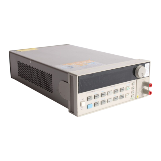
- Page 1 Keysight Models 6611C, 6612C, 6613C, and 6614C System DC Power Supplies Service Manual...
-
Page 3: Warranty Information
90 days from date of delivery. During the warranty period Keysight Technologies will, at its option, either repair or replace products which prove to be defective. Keysight Technologies does not warrant that the operation for the software firmware, or hardware shall be uninterrupted or error free. -
Page 4: Safety Summary
Because of the danger of introducing additional hazards, do not install substitute parts or perform any unauthorized modification to the instrument. Return the instrument to a Keysight Technologies Sales and Service Office for service and repair to ensure that safety features are maintained. - Page 5 Safety Symbol Definitions Symbol Description Direct current Alternating current Both direct and alternating current Three-phase alternating current Earth (ground) terminal Protective earth (ground) terminal Frame or chassis terminal Terminal is at earth potential (Used for measurement and control circuits designed to be operated with one terminal at earth potential.) Terminal for Neutral conductor on permanently installed equipment Terminal for Line conductor on permanently installed equipment...
-
Page 6: Notice
Instrument Identification Keysight Technologies power supplies are identified by a 10-digit serial number. The format is described as follows: first two letters indicate the country of manufacture. The next four digits are a code that identify either the date of manufacture or of a significant design change. -
Page 7: Table Of Contents
Table of Contents Warranty Information Safety Summary Notice Printing History Instrument Identification Table of Contents INTRODUCTION Organization Safety Considerations Related Documents Revisions Manual Revisions Firmware Revisions Electrostatic Discharge VERIFICATION AND PERFORMANCE TESTS Introduction Test Equipment Required Measurement Techniques Setup for Most Tests Electronic Load Current-Monitoring Resistor Operation Verification Tests... - Page 8 CV/CC Status Annunciators Troubleshooting Bias and Reference Supplies J307 Voltage Measurements Manual Fan Speed Control Disabling Protection Features Post-repair Calibration Inhibit Calibration Switch Calibration Password Initialization ROM Upgrade Identifying the Firmware Upgrade Procedure Disassembly Procedures List of Required Tools Cover, Removal and Replacement A2 Interface Board, Removal and Replacement Front Panel Assembly, Removal and Replacement A3 Front Panel Board, Removal and Replacement...
-
Page 10: Introduction
Introduction Organization This manual contains information for troubleshooting and repairing Keysight Models 6611C, 6612C, 6613C and 6614C System DC Power Supplies. Hereafter all models will be referred to as the dc power supply. This manual is organized as follows: Chapter 1... -
Page 11: Revisions
1 - Introduction Revisions Manual Revisions If changes have been made to your power supply since the publication of this manual, a yellow Manual Change sheet may be supplied with the manual. It defines the differences between your power supply and the unit described in this manual. -
Page 12: Verification And Performance Tests
Verification and Performance Tests Introduction This document contains test procedures to verify that the dc power supply is operating normally and is within published specifications. There are three types of tests as follows: Built-in Self Tests These tests, run automatically when the power supply is turned on, check most of the digital circuits and the programming and readback DACs. -
Page 13: Measurement Techniques
Keysight p/n 0811-1857 1 ohm, 100 W (or 2 ohm adjustable) Ohmite D12K2R0 (2 ohm adjustable) (Load resistors may 0.6 ohm, 100W (6611C) substitute for electronic 9 ohm, 100W (6612C) load if load is too noisy 49 ohm, 100W (6613C) -
Page 14: Electronic Load
Verification and Performance Tests - 2 SENSE SENSE Local Local Remote Remote NOTE: Connector is removable 50VDC MAX TO 50VDC MAX TO Set to Set to Remote Remote DVM, Scope, or Load resistor RMS voltmeter Ammeter 400 ohm (for CV tests) DVM or Current RMS voltmeter... -
Page 15: Current-Monitoring Resistor
User’s Guide and in the Programming Guide. Table 2-2. Programming and Output Values Model Full scale Vmax Full Scale Imax Isink OV Max Voltage Current 6611C 8.190 5.1187 - 3 A 6612C 20.475 2.0475 - 1.2 A 6613C 51.187 1.0238 - 0.6 A... -
Page 16: Constant Voltage (Cv) Tests
Verification and Performance Tests - 2 Constant Voltage (CV) Tests CV Setup If more than one meter or if a meter and an oscilloscope are used, connect each to the terminals by a separate pair of leads to avoid mutual coupling effects. For constant voltage dc tests, connect only to +S and -S, since the unit regulates the output voltage that appears between +S and -S, and not between the (+) and (-) output terminals. -
Page 17: Cv Source Effect
2 - Verification and Performance Tests CV Source Effect This test measures the change in output voltage that results from a change in ac line voltage from the minimum to maximum value within the line voltage specifications. Turn off the supply and connect the ac power line through a variable voltage transformer. Connect the output as shown in Figure 2-1a with the DVM connected between the +S and the -S terminals. -
Page 18: Constant Current (Cc) Tests
Verification and Performance Tests - 2 Loading Transient tttt Unloading Transient Figure 2-2. Transient Waveform Turn off the supply and connect the output as in Figure 2-1a with the oscilloscope across the +S and -S terminals. Turn on the supply and program the output current to the maximum programmable value (Imax) and the voltage to the full-scale value in Table 2-2. -
Page 19: Current Sink (Cc-) Operation
2 - Verification and Performance Tests Divide the voltage drop (DVM reading) across the current monitoring resistor by its resistance to convert to amps and record this value (Iout). The readings should be within the limits specified in the performance test record card for the appropriate model under Current Programming @ 0 Amps. -
Page 20: Cc Load And Line Regulation
Verification and Performance Tests - 2 CC Load and Line Regulation These tests (CC Load Effect and CC Source Effect given below) are tests of the dc regulation of the power supply's output current. To insure that the values read are not the instantaneous measurement of the ac peaks of the output current ripple, several dc measurements should be made and the average of these readings calculated. -
Page 21: Cc Source Effect
2 - Verification and Performance Tests CC Source Effect This test measures the change in output current that results when the AC line voltage changes from the minimum to the maximum value within the specifications. Turn off the supply and connect the ac power line through a variable voltage transformer. Connect the output terminals as shown in Figure 2-1a with the DVM connected across the current monitoring resistor. -
Page 22: Performance Test Equipment Form
Verification and Performance Tests - 2 Performance Test Equipment Form Report Number ________________________ Test Facility:_________________________ ____________________________________ Date _________________________________ ____________________________________ Customer _____________________________ ____________________________________ Tested By ____________________________ Model ______________________________ Ambient Temperature (C) ________________ Serial No. ____________________________ Relative Humidity (%) ___________________ Options _____________________________ Nominal Line Frequency __________________ Firmware Revision ____________________ Special Notes:... -
Page 23: Performance Test Record Form
2 - Verification and Performance Tests Performance Test Record Form Model Keysight 6611C Report No _______________ Date __________________ Test Description Minimum Specs. Results* Maximum Specs. Constant Voltage Tests Voltage Programming and Readback 5 mV Low Voltage (0V) Vout __________ + 5 mV Vout ... - Page 24 Verification and Performance Tests - 2 Model 6612C Report No _______________ Date __________________ Test Description Minimum Specs. Results* Maximum Specs. Constant Voltage Tests Voltage Programming and Readback 10 mV Low Voltage (0V) Vout __________ + 10 mV Vout 3 mV Front Panel Display Readback __________ Vout + 3 mV...
- Page 25 2 - Verification and Performance Tests Model Keysight 6613C Report No _______________ Date __________________ Test Description Minimum Specs. Results* Maximum Specs. Constant Voltage Tests Voltage Programming and Readback 20 mV Low Voltage (0V) Vout __________ + 20 mV Vout 6 mV Front Panel Display Readback __________ Vout + 6 mV...
- Page 26 Verification and Performance Tests - 2 Model Keysight 6614C Report No _______________ Date __________________ Test Description Minimum Specs. Results* Maximum Specs. Constant Voltage Tests Voltage Programming and Readback 50 mV Low Voltage (0V) Vout __________ + 50 mV Vout 12 mV Front Panel Display Readback __________ Vout + 12 mV...
-
Page 28: Troubleshooting
Troubleshooting Introduction WARNING: SHOCK HAZARD. Most of the troubleshooting procedures given in this chapter are performed with power applied and protective covers removed. Such maintenance should be performed only by service trained personnel who are aware of the hazards (for example, fire and electrical shock). -
Page 29: Test Equipment Required
3 - Troubleshooting Test Equipment Required Table 3-1 lists the test equipment required to troubleshoot the power supply. Recommended models are listed. Table 3-1. Test Equipment Required for Troubleshooting Type Purpose Recommended Model GPIB Controller To communicate with the supply via the HP Series 200/300 GPIB interface Digital Voltmeter... - Page 30 Troubleshooting - 3 Turn on unit and observe the display. All of the segments and annunciators, the address and then after self test should display an error message or go to the metering mode. Check Bias voltages (see Table 3-3) Check Main Fuse, Bias voltages OK? Transformer Inputs...
- Page 31 3 - Troubleshooting From Sheet 1 Enable output and program voltage and current full scale with no load. Measure output voltage. Check to insure OV setting is not less than Unit OV's? the voltage setting. If not then replace A1. CV_Prog &...
- Page 32 Troubleshooting - 3 From Sheet 2 Program current to full scale, voltage to Vmax and load to the power supply's rated current. Supply should be in CC. CC_Prog OK ? Replace A1 Will not go into CC (see Table 3-4) or error >...
- Page 33 3 - Troubleshooting From Sheet 3 Connect controller to the HPIB port and send commands to set the output voltage and current and readback the output. Accepts and reads Replace A2 back? Run the Performance Test in Chapter 2. Regulation, Transient Response and ripple Passes test? problems are generally...
-
Page 34: Specific Troubleshooting Procedures
Troubleshooting - 3 Specific Troubleshooting Procedures Power-on Self-test Failures The power-on self-test sequence tests most of the digital and DAC circuits. If the supply fails self-test, the display "ERR" annunciator will come on. You can then query the unit to find out what the error(s) are. When an error is detected, the output is not disabled so you can still attempt to program the supply to help troubleshoot the unit. -
Page 35: Cv/Cc Status Annunciators Troubleshooting
+15V secondary A1 R419 (jumper) +15V +/- 0.6V -15V secondary A1 R422 (jumper) -15V +/- 0.6V 6611C +Rail A1 Main Heat Sink +20V +/- 10% (50mV P/P) 6612C +Rail A1 Main Heat Sink +32V +/- 10% (120mV P/P) 6613C +Rail... -
Page 36: J307 Voltage Measurements
Troubleshooting - 3 J307 Voltage Measurements Cable W9 connects J307 of the A1 Main Board Assembly to J207 of the A2 Interface Assembly. Table 3-4 provides a quick method of determining if the voltages between these assemblies are within the normal range. -
Page 37: Manual Fan Speed Control
3 - Troubleshooting Manual Fan Speed Control Under some circumstances such as testing acoustical devices where the fan noise would interfere with the test, it would be advantageous to reduce the fan speed. If the test requires a very light load, the ambient temperature is low and the duration of the test is short, the fan speed may be temporarily reduced. -
Page 38: Post-Repair Calibration
Troubleshooting - 3 Post-repair Calibration Calibration is required annually and whenever certain components are replaced. If either A1 or A2 are replaced, the supply must be re-calibrated as described in Appendix B of the User's Guide. If the Interface board A2 is replaced, the supply must be initialized first (see "Initialization" later in this chapter) and then be calibrated. -
Page 39: Initialization
3 - Troubleshooting Initialization The dc power supply's GPIB address and model number as well as other constants which are required to program and calibrate the supply are stored in a EEPROM on the A2 Interface board. The Interface board also contains references and other components that will affect the alignment of the supply. -
Page 40: Disassembly Procedures
Troubleshooting - 3 Disassembly Procedures The following paragraphs provide instructions on how to disassemble various components of the dc power supply. Once disassembled, the components can be reassembled by performing the disassembly instructions in reverse order. Figure 3-2 shows the location of the major components of the unit. Figure 3-2. -
Page 41: Cover, Removal And Replacement
3 - Troubleshooting Cover, Removal and Replacement Using a T15 Torx screwdriver, unscrew the two captive screws which hold the rear bezel to the dc power supply, and then remove the two screws from the bottom of the case. Slide the cover backward until it clears the rear of the power supply. A2 Interface Board, Removal and Replacement To remove the Interface Board, proceed as follows: Remove the cover of the power supply as described under, "Cover Removal and Replacement."... -
Page 42: A3 Front Panel Board, Removal And Replacement
Troubleshooting - 3 A3 Front Panel Board, Removal and Replacement First remove the front panel assembly as described under, "Front Panel Assembly, Removal and Replacement." Once you have access to the front panel board perform these steps: Remove the RPG knob by pulling it away from the front panel. Pull back the right side of the board near the RPG about 1/8th of an inch. -
Page 43: Line Voltage Wiring
3 - Troubleshooting Line Voltage Wiring Figure 3-3 illustrates the primary wiring configuration of the power transformer for various ac line voltages. Use long nose pliers to disconnect the wires going to the transformer terminals. NOTE: Install the correct fuse when changing the ac line voltage from a previous setting: for 110/120 Vac: 2.5AT, 250V, Keysight p/n 2110-0633;... -
Page 44: Principles Of Operation
Principles of Operation Introduction This section describes the different functional circuits used in the dc power supply. First, the I/O external signals that connect to the Keysight power supply are described. Next, the overall block diagrams for the dc power supply are described in detail. The simplified block diagrams found in Chapter 6 show the major circuits on the dc power supply as well as the signals between circuits. -
Page 45: A3 Front Panel Circuits
4 - Principles of Operation A3 Front Panel Circuits As shown in Figure 6-3, the supply's front panel assembly contains a circuit board, a keypad, a display, and a rotary control (RPG) for the output voltage and current. With the exception of the RPG (A3G1), the A3 Front Panel board is an assembly-level replaceable part. -
Page 46: A1 Main Board Circuits
Principles of Operation - 4 The EEPROM (electrically erasable programmable read-only memory) chip on the A2 interface board stores a variety of data and configuration information. This information includes calibration constants, GPIB address, present programming language, and model-dependent data, such as the minimum and maximum values of voltage and current. -
Page 47: Control Circuits
4 - Principles of Operation As shown in Figure 6-2, the ac input rectifier and filter converts ac input to a dc level. The output regulator regulates this dc level at the output of the power supply. The output regulator stage consists of two parallel NPN series regulators mounted on a heatsink and connected between the +Rail and the +Output. - Page 48 Principles of Operation - 4 When the downprogramming stage is turned on (in either CV or CC mode), the CV/CC control circuit causes the Control signal to go low, which in turn causes the downprogramming transistors to conduct current away from the load and speed up downprogramming. During operation, a PM_Inhibit signal will cause the output stage bias/shutdown circuit to turn off the gated 15 V bias voltages and shut down the output if any of the following occur: The output is programmed off.
-
Page 50: Replaceable Parts List
F306 2110-0699 Fuse, sub-min, 5AM, 125V F308 2110-0932 Fuse, smt, 5AM, 125V F309 2110-0685 Fuse, sub-min, 7AT 125V (6611C Output Fuse) F309 2110-0967 Fuse, sub-min, 4AT 125V (6612C Output Fuse) F309 2110-0967 Fuse, sub-min, 4AT 125V (6613C Output Fuse) F309... - Page 51 Interface Signal/Bias Cable (A1J307 to A2J207) W-10 06611-60056 T1 Primary Jumper W-11 5080-2605 Relay Cable (J320 to relay board) not used in 6611C 8120-4383 Line Cord, (std U.S. 115Vac input) 8120-1351 Line Cord, Option 900, 8120-1369 Line Cord, Option 901,...
- Page 52 Replaceable Parts List - 5 Figure 5-1. Mechanical Parts Identification...
- Page 53 Front Panel 5040-1723 Side Bracket, Right 1400-0977 Battery Clip 1510-0091 Binding Post 0590-0305 Hex Nut 6-32 w/Lockwasher 33120-87401 Knob 06611-40008 Window (6611C) 06612-40003 Window (6612C) 06613-40001 Window (6613C) 06614-40001 Window (6614C) 06611-40001 Pushrod (Ref Line Switch) MP10 06611-40002 Keypad MP11...
-
Page 54: Diagrams
Diagrams Introduction This chapter contains drawings and diagrams for troubleshooting and maintaining the Keysight Model 6611C, 6612C, 6613C and 6614C System DC Power Supplies. J320 Conductor Side J307 F310 F308 +5Vp +5Vp (unreg) Pri Common Figure 6-1. A1 Board Component and Test Point Locations... - Page 55 6 - Diagrams Figure 6-2. A1 Board Block Diagram...
- Page 56 Diagrams - 6 Figure 6-3. A2/A3 Boards Block Diagram...
- Page 57 6 - Diagrams Figure 6-4. Rail and Bias Circuits...
-
Page 58: Index
Index —+— —D— +OUT, 43 DAC, 44 +sense, 43 disable protection, 36 disassembly - tools, 39 —A— disassembly procedure, 39 downprogramming, 45, 47 DP_Control, 45 A1 block diagram, 54 A1 board removal, 41 —E— A1 Main board, 45 A1 test point locations, 53 EEPROM, 45 A2 board removal, 40 A2 Interface Board, 44... - Page 59 Index —M— test equipment, 11 test setup, 12 manual revisions, 10 trademarks, 5 transformer removal, 41 transient recovery, 16 —N— troubleshooting - bias and reference supplies, 34, 35 troubleshooting - equipment, 28 notice, 5 troubleshooting - flowcharts, 28 troubleshooting - introduction, 27 —O—...
- Page 60 Index This information is subject to change without notice. © Keysight Technologies 1998, 2000, 2014 Edition 3, December 2014 5962-8200 www.keysight.com...
Need help?
Do you have a question about the 6611C and is the answer not in the manual?
Questions and answers