Table of Contents
Advertisement
Quick Links
Advertisement
Table of Contents

Related Manuals for Keysight Technologies E36100B Series


Summary of Contents for Keysight Technologies E36100B Series
- Page 1 Operating and Service Guide E36100B Series Programmable DC Power Supplies...
-
Page 2: Table Of Contents
Configure the Power-on State Read error codes Remote Control Keysight IO Libraries Suite E36100B Series Web interface Technical connection details Rack Mounting the Instrument Rack mounting a single instrument Rack mounting multiple instruments side-by-side Keysight E36100B Series Operating and Service Guide... - Page 3 [SOURce:]CURRent:PROTection:DELay[:TIME] <time> | MINimum | MAXimum[SOURce:]CURRent:PROTec- tion:DELay[:TIME]? [MINimum | MAXimum] [SOURce:]CURRent:PROTection:STATe ON|1|OFF|0[SOURce:]CURRent:PROTection:STATe? [SOURce:]CURRent:PROTection:TRIPped? DISPlay Subsystem DISPlay[:WINDow]:TEXT:CLEar DISPlay[:WINDow]:TEXT[:DATA] "<string>"DISPlay[:WINDow]:TEXT[:DATA] DISPlay[:WINDow][:STATe] ON | 1 | OFF | 0DISPlay[:WINDow][:STATe]? IEEE-488 Subsystem *CLS *ESE <enable value>*ESE? *ESR? *IDN? *OPC*OPC? Keysight E36100B Series Operating and Service Guide...
- Page 4 TRIGger[:SEQuence]:SOURce BUS | IMMediateTRIGger[:SEQuence]:SOURce? VOLTage Subsystem [SOURce:]VOLTage[:LEVel][:IMMediate][:AMPLitude] <voltage>|MINimum|MAXimum|DEFault [SOURce:]VOLTage[:LEVel][:IMMediate][:AMPLitude]? [MINimum | MAXimum] [SOURce:]VOLTage[:LEVel][:IMMediate]:STEP[:INCRement] <numeric value>|DEFault[SOURce:]VOLTage [:LEVel][:IMMediate]:STEP[:INCRement]? [DEFault] [SOURce:]VOLTage[:LEVel]:TRIGgered[:AMPLitude] <voltage>|MIN|MAX[SOURce:]VOLTage[:LEVel]:TRIGgered [:AMPLitude]? [MIN|MAX] [SOURce:]VOLTage:PROTection:CLEar [SOURce:]VOLTage:PROTection:STATe ON|1|OFF|0[SOURce:]VOLTage:PROTection:STATe? [SOURce:]VOLTage:PROTection:TRIPped? [SOURce:]VOLTage:PROTection[:LEVel] <voltage>|MINimum | MAXimum[SOURce:]VOLTage:PROTection [:LEVel]? [MINimum|MAXimum] [SOURce:]VOLTage:SENSe[:SOURce] INTernal | EXTernal Keysight E36100B Series Operating and Service Guide...
- Page 5 Calibration Adjustment Procedures Closed–case electronic calibration Calibration interval Calibration adjustment process Calibration security Calibration count Calibration message Saving calibration data Calibration auto save Calibration procedure Save the calibration data Specifications and Typical Characteristics Keysight E36100B Series Operating and Service Guide...
-
Page 6: Notices
No part of this manual may be reproduced in any form or by any means (including electronic storage and retrieval or translation into a foreign language) without prior agreement and written consent from Keysight Technologies as governed by United States and international copyright laws. -
Page 7: U.s. Government Rights
Declarations of Conformity for this product and for other Keysight products may be downloaded from the Web. Go to https://regulations.about.keysight.com/DoC/default.htm. You can then search by product number to find the latest Declaration of Conformity. Keysight E36100B Series Operating and Service Guide... -
Page 8: Safety Information
A WARNING notice denotes a hazard. It calls attention to an operating procedure, practice, or the like that, if not correctly per- formed or adhered to, could result in personal injury or death. Do not proceed beyond a WARNING notice until the indicated con- ditions are fully understood and met. Keysight E36100B Series Operating and Service Guide... -
Page 9: Safety And Regulatory Information
Because of the danger of introducing additional hazards, do not install substitute parts or perform any unauthorized modification to the instrument. Return the instrument to a Keysight Technologies Sales and Service Office for ser- vice and repair to ensure that safety features are maintained. To contact Keysight for sales and technical support, refer to the support links on the following Keysight website: www.keysight.com/find/assist... -
Page 10: Safety Symbols
CAUTION sign until the indicated conditions are fully understood and met. The NOTE sign denotes important information. It calls attention to a procedure, practice, condition or the like, which is essential to highlight. Keysight E36100B Series Operating and Service Guide... -
Page 11: Regulatory Markings
Safety and EMC Requirements This power supply is designed to comply with the following safety and EMC (Electromagnetic Compatibility) requirements: – Low Voltage Directive (2014/35/EU) – EMC Directive (2014/30/EU) – IEC61010-1:2010/EN61010-1:2010 – IEC61326-1:2012/EN61326-1:2013 Keysight E36100B Series Operating and Service Guide... -
Page 12: Environmental Conditions
Environmental Conditions The E36100B Series is designed for indoor use and in an area with low condensation. The table below shows the general environmental requirements for this instrument. Environmental condition Requirement Temperature Operating condition: 0 °C to 40 °C Storage condition: –20 °C to 70 °C Humidity Operating condition: Up to 80% RH at 40 °C (non-condensing) -
Page 13: Getting Started
Options and Fuse Information Programming Ranges Extending the Voltage Range and Current Range Front-panel Operation Remote Control Rack Mounting the Instrument This chapter describes the general operating information for the E36100B Series programmable DC power supplies. Keysight E36100B Series Operating and Service Guide... -
Page 14: Introduction
Introduction The Keysight E36100B Series is a series of DC bench and system power supplies with the following features and characteristics: – Single output up to 100 V or 5 A – Small size: two rack-units (2U), 1/4-rack form factor –... -
Page 15: Rear Panel
Rear panel The rear panel includes the power input, standard LAN and USB ports, and a security slot. Always use the power cord that arrived with the instrument or one with equivalent ratings. Keysight E36100B Series Operating and Service Guide... -
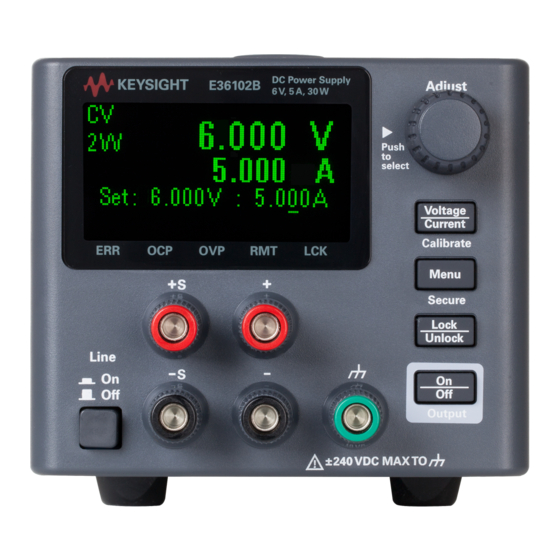
Page 16: Display
Meaning ERR An error has occurred. OCP An overcurrent protection event has occurred. OVP An overvoltage protection event has occurred. RMT The instrument is being programmed remotely. LCK The front panel is locked. Keysight E36100B Series Operating and Service Guide... -
Page 17: Dimension Diagram
Connect LAN or USB cables as desired, and you may also secure the instrument with a security lock cable. Before disconnecting cables and cords from the instrument, turn the instrument off using the front-panel power switch and disconnect from the supply source by unplugging the detachable power cord. Keysight E36100B Series Operating and Service Guide... -
Page 18: Options And Fuse Information
For example, to select 230 V, slide the left switch to the left and the right switch to the right, as illustrated in the diagram below the switches. To select 115 V, slide both switches to the right, and to select 100 V, slide the two switches towards each other. Keysight E36100B Series Operating and Service Guide... - Page 19 To configure the correct fuse, follow the three steps shown below: Pull the fuse holder out of the Remove and insert the proper Re-insert the fuse holder into the power supply. fuse into the fuse holder. power supply. Keysight E36100B Series Operating and Service Guide...
-
Page 20: Programming Ranges
E36104B 0.001 V 0.001 V 0.001 A 0.001 A 0.001 mA E36105B 0.001 V 0.01 V 0.001 A 0.0001 A 0.001 mA E36106B 0.001 V 0.01 V 0.001 A 0.0001 A 0.001 mA Keysight E36100B Series Operating and Service Guide... -
Page 21: Extending The Voltage Range And Current Range
Series connections You can connect up to four E36100B Series power supplies up to the output isolation rating of any one supply to obtain a higher voltage than a single power supply can produce. Series-connected power supplies can be operated with one load across both power supplies or with a separate load for each power supply. -
Page 22: Front Panel Operation
8. Turn the knob to the desired Gateway address. Then press the knob to select. 9. The instrument will briefly display CHANGE SAVED to indicate success. 10. Press [Menu] to exit the menu system. Keysight E36100B Series Operating and Service Guide... -
Page 23: Set Voltage And Current
The external setting sets a relay within the power supply to disconnect the output and remote sensing inputs. This means that four wires are used; and remote sensing is enabled. Keysight E36100B Series Operating and Service Guide... -
Page 24: Configure Overcurrent Protection (Ocp) And Overvoltage Protection (Ovp)
4. Turn the knob to the desired OCP or OVP limit value (if it needs to be changed). Then press the knob. 5. Turn the knob to OCP Clear or OVP Clear and press the knob. Keysight E36100B Series Operating and Service Guide... -
Page 25: Clear An Overtemperature Protection (Otp) Event
2. If you press a key after the front panel is locked, the display will read HOLD KEY. That message indicates that you must press and hold the [Lock / Unlock] key to unlock the front panel and clear the LCK triangle. Keysight E36100B Series Operating and Service Guide... -
Page 26: Save Or Recall The Instrument's State
2. Turn the knob to Error and press the knob. The instrument will briefly display a message like 3 ERRORS (the number will vary) to indicate how many errors are in the queue. 3. Turn the knob to cycle through the error codes, recording them as you go. Keysight E36100B Series Operating and Service Guide... -
Page 27: Remote Control
Check the checkbox below the picture of the instrument to enable an indicator on the instrument's front panel. This is helpful if you have several E36100B Series instruments and you wish to identify the one to which you are connected. - Page 28 "turn" the knob. You can click the knob to "push" it, just as you would push any of the other keys on the front panel. Read warning Be sure to read and understand the warning at the top of the Control Instrument page. Keysight E36100B Series Operating and Service Guide...
-
Page 29: Technical Connection Details
ASCII/SCPI commands, queries, and query responses. All commands must be terminated with a newline for the message to be parsed. All query responses will also be terminated with a newline. Keysight E36100B Series Operating and Service Guide... -
Page 30: Rack Mounting The Instrument
Rack mount kit with flange for 2 units (E36102-66503) Rack mount kit with flange for 3 units (E36102-66504) Rack mount kit with flange for 4 units (E36102-66505) Rack mount kit with flange and handles for 4 units (E36102-66506) Keysight E36100B Series Operating and Service Guide... - Page 31 Keysight E36100B Series Operating and Service Guide...
-
Page 32: Scpi Programming
CALibration Subsystem CURRent Subsystem DISPlay Subsystem IEEE-488 Subsystem MEASure Subsystem OUTPut Subsystem STATus Subsystem SYSTem Subsystem Triggering Commands VOLTage Subsystem This chapter describes the programming information for the E36100B Series programmable DC power supplies. Keysight E36100B Series Operating and Service Guide... -
Page 33: Introduction To The Scpi Language
SOURce is the root keyword of the command, CURRent and VOLTage are second-level keywords, and TRIGgered is the third- level keyword. A colon (:) separates a command keyword from a lower- level keyword. Keysight E36100B Series Operating and Service Guide... -
Page 34: Command Format Used In This Manual
A colon (:) separates a command keyword from a lower-level keyword. You must insert a blank space to separate a parameter from a command keyword. If a command requires more than one parameter, you must separate adjacent parameters using a comma as shown below: SOURce:CURRent:TRIGgered APPLy 3.5,1.5 Keysight E36100B Series Operating and Service Guide... -
Page 35: Command Separators
To avoid this, do not send a query command without reading the response. When you cannot avoid this situation, send a device clear before sending the second query command. Keysight E36100B Series Operating and Service Guide... -
Page 36: Scpi Command Terminators
OFF or 0. For a true condition, the power supply will accept ON or 1. When you query a boolean setting, the power supply will always return 0 or 1. The following command uses a boolean parameter: DISP {OFF|ON} Keysight E36100B Series Operating and Service Guide... - Page 37 You can include the quote delimiter as part of the string by typing it twice without any characters in between. The following command uses a string parameter: DISP:TEXT <quoted string> Keysight E36100B Series Operating and Service Guide...
-
Page 38: Error Messages
-410,"Query INTERRUPTED" -400,"Query error" -363,"Input buffer overrun" -350,"Queue overflow" -330,"Self-test failed" -310,"System error" -277,"Macro redefinition not allowed" -276,"Macro recursion error" -273,"Illegal macro label" -272,"Macro execution error" -270,"Macro error" -241,"Hardware missing" -230,"Data corrupt or stale" Keysight E36100B Series Operating and Service Guide... - Page 39 -138,"Suffix not allowed" -134,"Suffix too long" -131,"Invalid suffix" -128,"Numeric data not allowed" -124,"Too many digits" -123,"Exponent too large" -121,"Invalid character in number" -114,"Header suffix out of range" -113,"Undefined header" -112,"Program mnemonic too long" Keysight E36100B Series Operating and Service Guide...
- Page 40 616,"Model no mismatched" 630,"Fan test failed" 631,"System DAC test failed" 701,"Cal security disabled by jumper" 702,"Invalid state. Cal secured" 703,"Invalid secure code" 704,"Secure code too long" 708,"Cal output disabled" 717,"Cal OVP or OCP status enabled" Keysight E36100B Series Operating and Service Guide...
- Page 41 721,"Failed to calibrate voltage DAC" 722,"Failed to calibrate voltage ADC" 723,"Failed to calibrate OVP" 724,"Failed to calibrate current DAC" 725,"Failed to calibrate current ADC" 726,"Failed to calibrate OCP" 727,"Invalid Calibration sequence" 728,"Calibration failed" Keysight E36100B Series Operating and Service Guide...
-
Page 42: Scpi Status Registers
(clear status) command does not clear enable registers but it does clear the bits in the event registers. To enable bits in an enable register, you must write a decimal value which corresponds to the binary- weighted sum of the bits you wish to enable in the register. Keysight E36100B Series Operating and Service Guide... -
Page 43: Standard Event Status Enable Register
Description Output disabled by overvoltage protection Output disabled by overcurrent protection (unused) (reserved for future use) Output disabled by overtemperature protection 5-9 32-512 (unused) (reserved for future use) 10 1024 Output is unregulated Keysight E36100B Series Operating and Service Guide... - Page 44 Keysight E36100B Series Operating and Service Guide...
-
Page 45: Apply Subsystem
– The DEFault, MINimum, and MAXimum values for each mode are shown in Programming Ranges. – The query returns a quoted string with the voltage setting before the current setting. – Both values returned by the query have five decimal points: "25.00000,0.75000" Keysight E36100B Series Operating and Service Guide... -
Page 46: Calibration Subsystem
– The front panel limits the user to entering codes of up to six digits. – The default passcodes are 36102, 36103, 36104, 36105, and 36106. – Example: Unlock the instrument to enable calibration: CAL:STATe 1,36102 Keysight E36100B Series Operating and Service Guide... -
Page 47: Calibration:string "
– This command can only be used when calibration is unsecured and output is ON. CALibration:VOLTage:LEVel MINimum|MAXimum Initiates calibration for a specific voltage level. You must do the MINimum calibration before the MAXimum, and this command can only be used when calibration is unsecured. Keysight E36100B Series Operating and Service Guide..."Calibration:string -
Page 48: Current Subsystem
The query returns 1 (ON) or 0 (OFF). [SOURce:]CURRent:PROTection:TRIPped? Indicates whether an overcurrent protection occurred (1) or not (0). This is reset to 0 by CURRent:PROTection:CLEar. Keysight E36100B Series Operating and Service Guide... -
Page 49: Display Subsystem
Turns the display off or on. When the display is turned off, outputs are not sent to the display and all annunciators except ERROR are disabled. The display state is automatically turned on when you return to the local mode. Press and hold [Lock/Unlock] for a few seconds to return to the local mode. Keysight E36100B Series Operating and Service Guide... -
Page 50: Ieee-488 Subsystem
0. The bit configuration is the same as the Standard Event Status Enable register (see *ESE). *IDN? Returns the power supply’s identification string in the form shown below. Keysight Technologies,E36102B,MY87654321,0.3.2-0.32 The four comma-separated fields are the manufacturer name, instrument model number, instrument serial number, and revision code. Keysight E36100B Series Operating and Service Guide... -
Page 51: Opc*Opc
– States are not affected by the *RST command. – Saving a state overwrites the previous state (if any) stored in that location. – When shipped from the factory, storage locations 0 through 9 are empty. Keysight E36100B Series Operating and Service Guide... -
Page 52: Sre
128 (unused) (reserved for future use) *WAI Waits for all pending operations to complete before executing any additional remote interface commands. This command is used only in the triggered mode to wait for a pending delayed trigger. Keysight E36100B Series Operating and Service Guide...*Sre -
Page 53: Measure Subsystem
Returns the sensed DC output current in amps in the format 1.23456789E+00. MEASure[:VOLTage][:DC]? Returns the sensed DC output voltage in volts in the format 1.23456789E+00. Use the [SOURce:]VOLTage:SENSe [:SOURce] command to specify whether the voltage uses internal or external (remote) sensing. Keysight E36100B Series Operating and Service Guide... -
Page 54: Output Subsystem
You can then restore the output to the state that existed before the fault condition occurred. OUTPut:PON:STATe RST|RCL0|RCL1|RCL2|RCL3|RCL4|RCL5|RCL6|RCL7|RCL8|RCL9| OUTPut:PON:STATe? Specifies whether the instrument's power-on state is the *RST state (default) or the state stored in one of ten memory locations. Keysight E36100B Series Operating and Service Guide... -
Page 55: Status Subsystem
– This register is a read-only register, which holds the instrument's live (unlatched) operational status. – Reading the Questionable Status Condition register does not clear it. – *RST clears this register, other than those bits where the condition still exists after *RST Keysight E36100B Series Operating and Service Guide... -
Page 56: Status:questionable:enable
Returns a decimal value corresponding to the binary-weighted sum of all bits in the Questionable Status event register. – These bits are latched. – Reading the event register clears it, but *RST has no effect on this register. Keysight E36100B Series Operating and Service Guide...Status:questionable:enable -
Page 57: System Subsystem
Places the power supply into remote mode for remote operation. When the unit is being controlled remotely, the power supply will go to remote mode automatically. You can switch the instrument to local mode using SYSTem:LOCal or by pressing any key on the front panel. Keysight E36100B Series Operating and Service Guide... -
Page 58: System:rwlock
MAC address and calibration data) is not erased. This procedure is not recommended for routine use because of the possibility of unintended data loss. SYSTem:VERSion? Returns the SCPI version on which the instrument's command set is based, which is 2005.0. Keysight E36100B Series Operating and Service Guide... -
Page 59: Triggering Commands
*WAI (wait) command. You can also use the *OPC? (operation complete) query or the *OPC command to indicate when the operation has completed. The query returns BUS (wait for trigger command) or IMM (continuous triggering). Keysight E36100B Series Operating and Service Guide... -
Page 60: Voltage Subsystem
Indicates whether an overvoltage protection occurred (1) or not (0). This is reset to 0 by VOLTage:PROTection:CLEar. [SOURce:]VOLTage:PROTection[:LEVel] <voltage>|MINimum | MAXimum[SOURce:]VOLTage:PROTec- tion[:LEVel]? [MINimum|MAXimum] Sets the level at which overvoltage protection trips, in volts. The query returns a number of the form +#.########E+##. Keysight E36100B Series Operating and Service Guide... -
Page 61: [Source:]Voltage:sense[:Source] Internal | External
This means that four wires are used; and remote sensing is enabled. The Internal setting displays 2W in the upper left corner of the display, and the External setting shows 4W in the upper left corner. Keysight E36100B Series Operating and Service Guide... -
Page 62: Service And Support
Service and Support Service and Repair Performance Verification Test Record Forms Calibration Adjustment Procedures Specifications and Typical Characteristics This chapter describes the service information for the E36100B Series programmable DC power supplies. Keysight E36100B Series Operating and Service Guide... -
Page 63: Service And Repair
Types of service available If your instrument fails during the warranty period, Keysight Technologies will repair or replace it under the terms of your warranty. After your warranty expires, Keysight offers repair services at competitive prices. You also have the option to purchase a service contract that extends the coverage after the standard warranty expires. -
Page 64: Troubleshooting
– Use the 2.0 AT, 250 V fuse for 100 or 115 Vac operation. – Use the 1.0 AT, 250 V fuse for 230 Vac operation. – Verify the power-line voltage setting. – See Getting Started > Options and Fuse Information for details. Keysight E36100B Series Operating and Service Guide... -
Page 65: Self-Test Procedures
For 100 or 115 Vac operation, you must use a 2.0 AT time-delay fuse. For 230 Vac operation, you must use a 1.0 AT time-delay fuse. User replaceable parts You can find the instrument support part list at Keysight's Test & Measurement Parts Catalog http://www.keysight.com/find/parts. Keysight E36100B Series Operating and Service Guide... -
Page 66: Performance Verification
– Ensure that the calibration ambient temperature is stable and between 20 °C and 30 °C. – Ensure ambient relative humidity is less than 80%. – Allow a 1-hour warm-up period before verification or calibration. – Keep cables as short as possible, consistent with the impedance requirements. Keysight E36100B Series Operating and Service Guide... -
Page 67: Measurement Techniques
"Wait" statements can be used in the test program if the test system is faster than the power system. Setup for most tests Keysight E36100B Series Operating and Service Guide... -
Page 68: Constant Voltage (Cv) Verification
MEAS:VOLT? (for example for the E36102B, 6 V, 5 A output) 10. Record the voltage returned by the SCPI command query via Keysight Connection Expert, and verify whether it is within the limits calculated. Keysight E36100B Series Operating and Service Guide... - Page 69 8. Take the difference between the DMM readings in steps 6 and 7 that is the CV load regulation (V load – V noload ). The difference of the readings during the immediate change should be within the specification limits. Keysight E36100B Series Operating and Service Guide...
- Page 70 10. Take the difference between the DMM readings in steps 8 and 9 that is the CV line regulation (V lowline – V high- line ). The difference of the readings during the immediate change should be within the limit calculated from the specification. Keysight E36100B Series Operating and Service Guide...
- Page 71 7. Adjust the oscilloscope to display transients as shown below. Note that the pulse width (t2-t1) of the transient at the voltage settling band, for example 15 mV for the E36102B from the base line is no more than 50 ms. Keysight E36100B Series Operating and Service Guide...
- Page 72 The oscilloscope cursors X1 and X2 represent t1 and t2. 8. Transient response specification is met when the voltage recovers within 50 μs. Keysight E36100B Series Operating and Service Guide...
- Page 73 AC coupling. Set the oscilloscope’s time base to 5 ms/div, and the vertical scale to 10 mV/div. Turn the bandwidth limit on (usually 20 or 30 MHz), and set the sampling mode to peak detect. Keysight E36100B Series Operating and Service Guide...
- Page 74 Divide the reading of the rms voltmeter by 10. The result should not exceed the rms limits in the test record form for the appropriate model under “CV Ripple and Noise, rms”. See the Test Record Forms under “CV Ripple and Noise” for details. Keysight E36100B Series Operating and Service Guide...
-
Page 75: Constant Current (Cc) Verification
MEAS:CURR? (for example for the E36102B, 6 V, 5 A output) 11. Record the current returned by the SCPI command query via Keysight Connection Expert, and verify whether it is within the limits calculated. Keysight E36100B Series Operating and Service Guide... - Page 76 8. Take the difference between the current readings in steps 6 and 7 is the load regulation current (I load – I short ). The difference of the readings during the immediate change should be within the specification limits. Keysight E36100B Series Operating and Service Guide...
- Page 77 9. Take the difference between the DMM readings in steps 7 and 8 is the CC line regulation (I lowline – I highline ). The difference of the readings during the immediate change should be within the specification limits. Keysight E36100B Series Operating and Service Guide...
-
Page 78: Test Record Forms
Current Readback Zero Current measured over interface I 0 - 0.004 A ______________ I 0 + 0.004 A Maximum Current measured over interface I max - 0.0065 A ______________ I max + 0.0065 A Keysight E36100B Series Operating and Service Guide... - Page 79 6 V Transient Response 2.5 A to 5 A Current Programming & Readback, Zero Current (I 0 ) Current Programming & Readback, Maximum Current (I max ) CC Load Regulation, Line Regulation, Ripple and Noise Keysight E36100B Series Operating and Service Guide...
-
Page 80: Test Record Form - Keysight E36103B
I max + 0.002 A CC Load Regulation (I load - I short ) -500 μA ______________ 500 μA CC Line Regulation (I lowline - I highline ) -500 μA ______________ 500 μA Keysight E36100B Series Operating and Service Guide... - Page 81 1 A to 2 A Current Programming & Readback, Zero Current (I 0 ) 20 V Current Programming & Readback, Maximum Current (I max ) 20 V CC Load Regulation, Line Regulation, Ripple and Noise 20 V Keysight E36100B Series Operating and Service Guide...
-
Page 82: Test Record Form - Keysight E36104B
I max + 0.001 A CC Load Regulation (I load - I short ) -250 μA ______________ 250 μA CC Line Regulation (I lowline - I highline ) -250 μA ______________ 250 μA Keysight E36100B Series Operating and Service Guide... - Page 83 0.5 A to 1 A Current Programming & Readback, Zero Current (I 0 ) 35 V Current Programming & Readback, Maximum Current (I max ) 35 V CC Load Regulation, Line Regulation, Ripple and Noise 35 V Keysight E36100B Series Operating and Service Guide...
-
Page 84: Test Record Form - Keysight E36105B
I max + 0.0006 A CC Load Regulation (I load - I short ) -150 μA ______________ 150 μA CC Line Regulation (I lowline - I highline ) -150 μA ______________ 150 μA Keysight E36100B Series Operating and Service Guide... - Page 85 Current Programming & Readback, Zero Current (I 0 ) 60 V Current Programming & Readback, Maximum Current (I max ) 0.6 A 60 V CC Load Regulation, Line Regulation, Ripple and Noise 0.6 A 60 V Keysight E36100B Series Operating and Service Guide...
-
Page 86: Test Record Form - Keysight E36106B
I max + 0.0004 A CC Load Regulation (I load - I short ) -100 μA ______________ 100 μA CC Line Regulation (I lowline - I highline ) -100 μA ______________ 100 μA Keysight E36100B Series Operating and Service Guide... - Page 87 Current Programming & Readback, Zero Current (I 0 ) 100 V Current Programming & Readback, Maximum Current (I max ) 0.4 A 100 V CC Load Regulation, Line Regulation, Ripple and Noise 0.4 A 100 V Keysight E36100B Series Operating and Service Guide...
-
Page 88: Calibration Adjustment Procedures
Calibration Adjustment Procedures This chapter includes calibration adjustment procedures for Keysight E36100B Series power supplies. Instructions are applicable for performing the procedures from either the front panel or a controller over the LAN or USB. Perform the verification tests before calibrating your instrument. If the instrument passes the verification tests, the unit is operating within its calibration limits and does not need to be re-calibrated. -
Page 89: Calibration Security
You can enter a security code of up to 6 digits on the front panel or up to 9 digits from the remote interface. To reset a forgotten security code to its factory default, you can turn on the instrument after shorting CAL SECURE jumper J3 inside the instrument as shown below. Keysight E36100B Series Operating and Service Guide... -
Page 90: Calibration Count
Front panel SCPI Press and hold [Calibrate] while powering ON the unit. Press [Secure], then turn the knob to the security code, pressing the knob to move CAL:STAT ON, <code> between digits. Press [Secure] when done. Keysight E36100B Series Operating and Service Guide... - Page 91 ) for your instrument model to the power sup- ply. Measure output current with the DMM. CAL:CURR:LEV:LOW MAX Enter the measured value, and press the knob. CAL:CURR:LOW <rdg> Read DONE or FAIL on the display. (wait 25 seconds) SYST:ERR? Keysight E36100B Series Operating and Service Guide...
-
Page 92: Save The Calibration Data
To enable the CAL Auto Save: CAL:ASAVE ON To exit CAL State: CAL:STAT OFF, 036102 Specifications and Typical Characteristics For the characteristics and specifications of the E36100B Series programmable DC power supplies, refer to the data- sheet at http://literature.cdn.keysight.com/litweb/pdf/5992-2437EN.pdf. Keysight E36100B Series Operating and Service Guide... - Page 93 This information is subject to change without notice. © Keysight Technologies 2017-2018 Edition 3, July 2018 Printed in Malaysia E36100-90002 www.keysight.com...
Need help?
Do you have a question about the E36100B Series and is the answer not in the manual?
Questions and answers