Table of Contents
Advertisement
Quick Links
Advertisement
Table of Contents

Related Manuals for Keysight Technologies E36100 Series


Summary of Contents for Keysight Technologies E36100 Series
- Page 1 Operating and Service Guide E36100 Series DC Power Supplies...
-
Page 3: Table Of Contents
Notices Copyright Notice Manual Part Number Edition Published by Warranty Technology Licenses U.S. Government Rights Waste Electrical and Electronic Equipment (WEEE) Declarations of Conformity Safety Information Safety and Regulatory Information Safety Considerations BEFORE APPLYING POWER GROUND THE INSTRUMENT DO NOT OPERATE IN AN EXPLOSIVE ATMOSPHERE OR WET ENVIRONMENTS DO NOT OPERATE DAMAGED OR DEFECTIVE INSTRUMENTS DO NOT SUBSTITUTE PARTS OR MODIFY INSTRUMENT BE CAUTIOUS WHEN DEALING WITH OUTPUTS ABOVE 60 VDC... - Page 4 To save or recall the instrument state Configure the Power-on State Read error codes Remote Control Keysight IO Libraries Suite E36100 Series Web interface Technical Connection Details SCPI Programming Introduction to the SCPI Language Command format used in this manual Command separators...
- Page 5 CALibration:CURRent:LEVel[:HIGH] MINimum|MAXimum CALibration:CURRent:LEVel:LOW MINimum|MAXimum CALibration:STATe <state>,<code>CALibration:STATe? CALibration:STRing "<string>"CALibration:STRing? CALibration:VOLTage[:DATA] <value> CALibration:VOLTage:LEVel MINimum|MAXimum CURRent Subsystem [SOURce:]CURRent[:LEVel][:IMMediate][:AMPLitude] <current> | MINimum | MAXimum | UP | DOWN [SOURce:]CURRent[:LEVel][:IMMediate][:AMPLitude]? [MINimum | MAXimum] [SOURce:]CURRent[:LEVel][:IMMediate]:STEP[:INCRement] <current> | DEFault[SOURce:]CURRent [:LEVel][:IMMediate]:STEP[:INCRement]? [DEFault] [SOURce:]CURRent[:LEVel]:TRIGgered[:AMPLitude] <current> | MINimum | MAXimum [SOURce:]CURRent[:LEVel]:TRIGgered[:AMPLitude]? [MINimum | MAXimum] [SOURce:]CURRent:PROTection:CLEar [SOURce:]CURRent:PROTection:DELay[:TIME] <time>...
- Page 6 STATus Subsystem STATus:OPERation:[EVENT]? STATus:OPERation:CONDition? STATus:OPERation:ENABle <value> STATus:PRESet STATus:QUEStionable:CONDition? STATus:QUEStionable:ENABle <enable value>STATus:QUEStionable:ENABle? STATus:QUEStionable[:EVENt]? SYSTem Subsystem SYSTem:ERRor[:NEXT]? SYSTem:LOCal SYSTem:REMote SYSTem:RWLock SYSTem:SECurity:IMMediate SYSTem:VERSion? Triggering Commands ABORt INITiate[:IMMediate] INITiate:CONTinuous ON | 1 | OFF | 0INITiate:CONTinuous? *TRG TRIGger[:SEQuence]:DELay <seconds> MINimum | MAXimumTRIGger[:SEQuence]:DELay? [MINimum | MAXimum] TRIGger[:SEQuence]:SOURce BUS | IMMediateTRIGger[:SEQuence]:SOURce? VOLTage Subsystem [SOURce:]VOLTage[:LEVel][:IMMediate][:AMPLitude] <voltage>|MINimum|MAXimum|DEFault...
- Page 7 To Replace the Power-Line Fuse User Replaceable Parts Performance Verification Recommended test equipment Test considerations Measurement techniques Voltmeter Current-monitoring resistor Electronic load Setup for most tests Constant Voltage (CV) verification Voltage programming and readback accuracy CV load and line regulation CV load regulation CV line regulation Transient response verification...
- Page 8 Storage Temperature Operating Temperature Environmental Conditions...
-
Page 9: Notices
No part of this manual may be reproduced in any form or by any means (including electronic storage and retrieval or translation into a foreign language) without prior agreement and written consent from Keysight Technologies as governed by United States and international copyright laws. Manual Part Number... -
Page 10: U.s. Government Rights
U.S. Government Rights The Software is “commercial computer software,” as defined by Federal Acquisition Regulation (“FAR”) 2.101. Pursuant to FAR 12.212 and 27.405-3 and Department of Defense FAR Supplement (“DFARS”) 227.7202, the U.S. government acquires commercial computer software under the same terms by which the software is customarily provided to the public. -
Page 11: Declarations Of Conformity
Declarations of Conformity Declarations of Conformity for this product and for other Keysight products may be downloaded from the Web. Go to http://regulations.corporate.keysight.com/DoC/search.htm and click on “Declarations of Conformity.” You can then search by product number to find the latest Declaration of Conformity. Safety Information A CAUTION notice denotes a hazard. -
Page 12: Safety And Regulatory Information
Failure to comply with these precautions or with specific warnings elsewhere in this manual violates safety standards of design, manufacture, and intended use of the instrument. Keysight Technologies assumes no liability for the customer's failure to comply with these requirements. BEFORE APPLYING POWER Verify that the product is set to match the available line voltage and that the correct fuse is installed. -
Page 13: Do Not Operate Damaged Or Defective Instruments
Because of the danger of introducing additional hazards, do not install substitute parts or perform any unauthorized modification to the instrument. Return the instrument to a Keysight Technologies Sales and Service Office for service and repair to ensure that safety features are maintained. -
Page 14: Clean With Slightly Dampened Cloth
CLEAN WITH SLIGHTLY DAMPENED CLOTH Clean the outside of the instrument with a soft, lint-free, slightly dampened cloth. Do not use detergent, volatile liquids, or chemical solvents. DO NOT BLOCK VENTILATION HOLES Do not block any of the ventilation holes of the device. OBSERVE ALL DEVICE MARKINGS BEFORE CONNECTING TO DEVICE Observe all markings on the device before connecting any wiring to the device. -
Page 15: Safety Symbols
Safety Symbols Symbol Meaning Caution, refer to accompanying documentation. Protective conductor terminal. Frame or chassis terminal. In position of bi-stable push control. Out position of bi-stable push control. Alternating current. Direct current. Plus, positive polarity. Minus, negative polarity. The WARNING sign denotes a hazard. It calls attention to a procedure, practice, or the like, which, if not correctly performed or adhered to, could result in personal injury. -
Page 16: Regulatory Markings
Regulatory Markings Symbol Meaning The RCM Mark is a Compliance Mark according to the ACMA Labeling Requirement. The CE marking is the legal required labeling for several EU Directives of the European Union. This CE marking shows that the product complies with all the relevant European Legal Directives. ISM 1-A This product is an Industrial Scientific and Medical Group 1 Class A product. -
Page 17: Safety And Emc Requirements
Safety and EMC Requirements This power supply is designed to comply with the following safety and EMC (Electromagnetic Compatibility) requirements: – Low Voltage Directive (2006/95/EC) – EMC Directive (2004/108/EC) – IEC61010-1:2010/EN61010-1:2010 – IEC61326-1:2012/EN61326-1:2013... -
Page 19: Getting Started
Getting Started Introduction Options and Fuse Information Programming Ranges Extending the Voltage Range and Current Range Front-panel Operation Remote Control... -
Page 20: Introduction
Introduction The Keysight E36100 Series is a series of DC bench and system power supplies with the following features and characteristics: – Single output up to 100 V or 5 A – Small size: 2U, 1/4 rack – Remote sense capability –... -
Page 21: Front Panel
Front Panel Item Description Tough carrying handle Information-packed, high-contrast OLED display; easily viewable even from sharp angles Rotary knob for quick and easy configuration Fast voltage/current setting and front-panel electronic calibration Menu key opens intuitive user interface Front-panel lock prevents accidental changes during tests Output enable/disable switch to protect your DUT quickly Dual-position power switch Sense terminals... -
Page 22: Rear Panel
Rear Panel The rear panel includes the power input, standard LAN and USB ports, and a security slot. Always use the power cord that arrived with the instrument or one with equivalent ratings. -
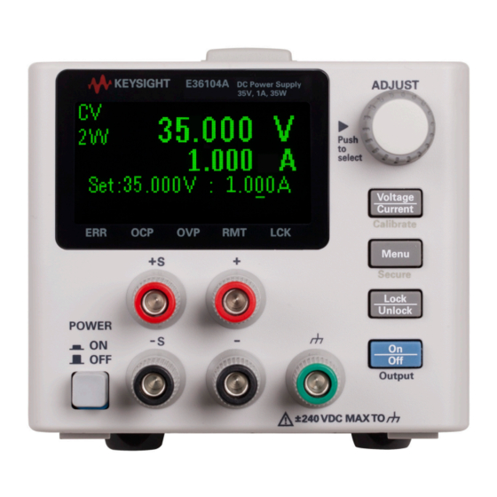
Page 23: Display
Display The power supply's front panel features a high-visibility OLED display. The upper left corner of the display shows either CV or CC to indicate that the instrument is in constant voltage or constant current mode. Below that is either 2W or 4W, to indicate whether 2-wire (normal) or 4-wire (remote sensing) measurement is in use. - Page 24 Before disconnecting cables and cords from the instrument, turn the instrument off using the front- panel power switch and disconnect from the supply source by unplugging the detachable power cord.
-
Page 25: Options And Fuse Information
Options and Fuse Information Be certain to order the proper instrument option for the mains power that will be used for the instrument. Options 0EM, 0E3, and 0E9 determine which power-line voltage is selected at the factory. The default is configured for 230 VAC ±... -
Page 26: Use The Correct Fuse
Use the correct fuse You must use a time delay 2-A fuse for 100- and 115-VAC inputs, and a time delay 1-A fuse for 230-VAC inputs: Part Number Description Manufacturer Application 2110-1639 Fuse 1A 250V Time-delay Littelfuse 230-V line voltage 2110-1640 Fuse 2A 250V Time-delay 100- and 115-V line voltage... -
Page 27: Programming Ranges
Programming Ranges The following table shows the maximum voltage, current, and power that can be programmed for each model. The DEFault voltage is always 0 V. Model Max Voltage (V) Max Current (A) Max Power (W) E36102A E36103A E36104A E36105A E36106A Note that the actual programmable values are 3% above these nominal values, but instrument specifications are only guaranteed up to the values shown in this table. -
Page 28: Extending The Voltage Range And Current Range
Series connections You can connect up to four E36100 Series power supplies up to the output isolation rating of any one supply to obtain a higher voltage than a single power supply can produce. Series-connected power supplies can be operated with one load across both power supplies or with a separate load for each power supply. -
Page 29: Front-Panel Operation
Front-panel Operation This section describes how to perform the following operations from the instrument's front panel. Configure the LAN interface Set voltage and current Specify 2- or 4-wire measurement Configure Overcurrent Protection (OCP) and Overvoltage Protection (OVP) Clear an OCP or OVP event Clear an overtemperature protection (OTP) event Lock and unlock the front panel Save or recall the instrument's state... -
Page 30: Set Voltage And Current
Set voltage and current If you are in a menu, you must exit the menu before setting the voltage and current. 1. Press [Voltage / Current] . 2. Turn the knob to the desired voltage value, pushing the knob to move between digits. 3. -
Page 31: Configure Overcurrent Protection (Ocp) And Overvoltage Protection (Ovp)
Configure Overcurrent Protection (OCP) and Overvoltage Protection (OVP) 1. Press [Menu] . 2. Turn the knob to OCP Set or OVP Set and press the knob. 3. Press the knob again to choose OCP Delay or OVP Level. 4. Turn the knob to the desired OCP or OVP limit value. Then press the knob. 5. -
Page 32: Clear An Overtemperature Protection (Otp) Event
Clear an overtemperature protection (OTP) event The instrument prominently displays an OTP TRIPPED message to indicate an OTP event. In addition, the triangle above ERR will flash continuously until the error event is cleared. The output will be automatically turned OFF when OTP occurs. The overtemperature event will be logged in the Error list, and you must clear the OTP event before the output can be turned ON again. -
Page 33: Save Or Recall The Instrument's State
Save or recall the instrument's state The instrument allows you to save and recall the instrument state in one of 10 memory locations, labeled 0 through 9. This allows you to quickly configure the instrument for commonly used applications. An instrument state includes the instrument's output enable status, voltage and current settings, and OCP and OCV settings. -
Page 34: Read Error Codes
Read error codes You only need to do this if there is a triangle over ERR in the lower left corner of the screen, as shown below. Be sure to follow the procedure below carefully, and record each error code in order. -
Page 35: Remote Control
LAN, USB, GPIB, RS-232, and other interfaces. For more information, or to download IO Libraries, go to www.keysight.com/find/iosuite. E36100 Series Web interface You can monitor control the instrument from a Web browser by using the instrument's Web interface. - Page 36 Check the checkbox below the picture of the instrument to enable an indicator on the instrument's front panel. This is helpful if you have several E36100 Series instruments and you wish to identify the one to which you are connected.
- Page 37 This interface allows you to use the instrument just as you would from the front panel. Note the curved arrow keys that allow you to "turn" the knob. You can click the knob to "push" it, just as you would push any of the other keys on the front panel.
-
Page 38: Technical Connection Details
Technical Connection Details In most cases, you can easily connect to the instrument with the IO Libraries Suite or Web interface. In certain circumstances, it may be helpful to know the following information. Interface Details VXI-11 VISA String: TCPIP0::<IP Address>::inst0::INSTR Example: TCPIP0::192.168.10.2::inst0::INSTR Web UI Port number 80, URL http://<IP address>/... -
Page 40: Scpi Programming
SCPI Programming Introduction to the SCPI Language Error Messages SCPI Status Registers APPLy Subsystem CALibration Subsystem CURRent Subsystem DISPlay Subsystem IEEE-488 Subsystem MEASure Subsystem OUTPut Subsystem STATus Subsystem SYSTem Subsystem Triggering Commands VOLTage Subsystem... -
Page 41: Introduction To The Scpi Language
Introduction to the SCPI Language Standard Commands for Programmable Instruments (SCPI) is an ASCII- based instrument command language designed for test and measurement instruments. Refer to Simplified Programming Overview for basic techniques for programming the power supply over the remote interface. SCPI commands are based on a hierarchical structure, also known as a tree system. -
Page 42: Command Format Used In This Manual
Command format used in this manual The format used to show commands in this manual is shown below: CURRent {<current>|MINimum|MAXimum|UP|DOWN} The command syntax shows most commands (and some parameters) as a mixture of upper- case and lower- case letters. The upper- case letters indicate the abbreviated spelling for the command. For shorter program lines, send the abbreviated form. -
Page 43: Command Separators
Command separators A colon (:) separates a command keyword from a lower- level keyword as shown below: SOURce:CURRent:TRIGgered A semicolon (;) is used to separate two commands within the same subsystem, and can also minimize typing. For example, sending the following command string, SOUR:VOLT MIN;CURR MAX is the same as sending the following two commands: SOUR:VOLT MIN... -
Page 44: Querying Parameter Settings
Querying parameter settings You can query the value of most parameters by adding a question mark (?) to the command. For example, the following command sets the output current to 5 A: CURR 5 You can query the value by executing: CURR? You can also query the maximum or minimum value allowed with the present function as follows: CURR? MAX CURR? MIN... -
Page 45: Scpi Parameter Types
SCPI parameter types The SCPI language defines several different data formats to be used in program messages and response messages. Numeric parameters Commands that require numeric parameters will accept all commonly used decimal representations of numbers including optional signs, decimal points, and scientific notation. Special values for numeric parameters like MINimum, MAXimum, and DEFault are also accepted. -
Page 46: Error Messages
Error Messages The instrument returns error messages in accordance with the SCPI standard. — Up to 20 errors can be stored in the instrument's error queue, and the triangle annunciator above ERR turns on when one or more errors are in the error queue. —... - Page 47 -270,"Macro error" -241,"Hardware missing" -230,"Data corrupt or stale" -225,"Out of memory" -224,"Illegal parameter value" -223,"Too much data" -222,"Data out of range" -221,"Settings conflict" -213,"Init ignored" -211,"Trigger ignored" -200,"Execution error" -183,"Invalid inside macro definition" -181,"Invalid outside macro definition" -178,"Expression data not allowed" -171,"Invalid expression"...
- Page 48 -121,"Invalid character in number" -114,"Header suffix out of range" -113,"Undefined header" -112,"Program mnemonic too long" -109,"Missing parameter" -108,"Parameter not allowed" -105,"GET not allowed" -104,"Data type error" -103,"Invalid separator" -102,"Syntax error" -101,"Invalid character" -100,"Command error" 514,"LAN config error" 561,"Analog board - failed to save to EEPROM" 564,"Analog board - failed to load from EEPROM"...
- Page 49 702,"Invalid state. Cal secured" 703,"Invalid secure code" 704,"Secure code too long" 708,"Cal output disabled" 717,"Cal OVP or OCP status enabled" 721,"Failed to calibrate voltage DAC" 722,"Failed to calibrate voltage ADC" 723,"Failed to calibrate OVP" 724,"Failed to calibrate current DAC" 725,"Failed to calibrate current ADC" 726,"Failed to calibrate OCP"...
-
Page 50: Scpi Status Registers
SCPI Status Registers All SCPI instruments implement status registers in the same way. The status system records various instrument conditions in three register groups: the Status Byte register, the Standard Event register, and the Questionable Status register groups. The Status Byte register records high-level summary information reported in the other register groups. -
Page 51: Standard Event Status Enable Register
Standard Event Status Enable Register Bit Value Name Description Operation complete (unused) (reserved for future use) Query error Device dependent error Execution error Command error (unused) (reserved for future use) Power-on Operation Status Register Bit Value Name Description The output is computing new calibration constants 1-4 2-16 (unused) (reserved for future use) The output is waiting for a trigger. -
Page 53: Apply Subsystem
APPLy Subsystem APPLy <voltage>| DEFault | MINimum | MAXimum[,<current>| DEFault | MINimum | MAXimum] APPLy? Specifies and changes the output voltage and current in one command. – The DEFault, MINimum, and MAXimum values for each mode are shown in Programming Ranges. -
Page 54: Calibration Subsystem
CALibration Subsystem Calibration Adjustment Procedures For a detailed discussion on the calibration procedures, see CALibration:COUNt? Returns the number of times the instrument has saved calibration data as a signed whole number, for example +21. Your instrument was calibrated at the factory; read and record the initial count when you receive the instrument. -
Page 55: Calibration:state
CALibration:STATe <state>,<code> CALibration:STATe? Unsecures or secures the power supply with the calibration security code Of up to nine digits. The query returns 1 (ON - unsecured for calibration) or 0 (OFF - secured against calibration). – The query only returns the state; it does not return the passcode. –..., Calibration:state -
Page 56: Current Subsystem
CURRent Subsystem [SOURce:]CURRent[:LEVel][:IMMediate][:AMPLitude] <current> | MINimum | MAXimum | UP | DOWN [SOURce:]CURRent[:LEVel][:IMMediate][:AMPLitude]? [MINimum | MAXimum] Programs the immediate current level of the instrument's output.See Programming Ranges for details. This command changes the output immediately. The UP and DOWN parameters increase or decrease the immediate current by the amount specified by CURRent:STEP. -
Page 57: [Source:]Current:protection:tripped
[SOURce:]CURRent:PROTection:TRIPped? Indicates whether an overcurrent protection occurred (1) or not (0). This is reset to 0 by CURRent:PROTection:CLEar. -
Page 58: Display Subsystem
DISPlay Subsystem DISPlay[:WINDow]:TEXT:CLEar Clears the message displayed on the front panel. DISPlay[:WINDow]:TEXT[:DATA] "<string>" DISPlay[:WINDow]:TEXT[:DATA] Displays a message of up to 12 characters on the front panel. Additional characters are truncated. DISPlay[:WINDow][:STATe] ON | 1 | OFF | 0 DISPlay[:WINDow][:STATe]? Turns the display off or on. When the display is turned off, outputs are not sent to the display and all annunciators except ERROR are disabled. -
Page 59: Ieee-488 Subsystem
0. The bit configuration is the same as the Standard Event Status Enable register (see *ESE). *IDN? Returns the power supply’s identification string in the form shown below. Keysight Technologies,E36102A,MY87654321,0.3.2-0.32 The four comma-separated fields are the manufacturer name, instrument model number, instrument serial number, and revision code. -
Page 60: Opc*Opc
*OPC *OPC? Sets the “Operation Complete” bit (bit 0) of the Standard Event register after the command is executed. The query returns 1 to the output buffer after the command is executed. *OPT? Returns the option number of the instrument. *PSC 0|1 *PSC? ( Power- on status clear ) Enables (1) or disables (0) the clearing of the Status Byte and the Standard... -
Page 61: Sre
*SRE <enable value> *SRE? Enables bits in the Status Byte enable register. The query returns the decimal value corresponding to the binary-weighted sum of all bits set in the register. *STB? Queries the Status Byte summary register. This is similar to a serial poll but it is processed like any other instrument command.*Sre -
Page 62: Measure Subsystem
MEASure Subsystem MEASure:CURRent[:DC]? Returns the sensed DC output current in amps in the format 1.23456789E+00. MEASure[:VOLTage][:DC]? Returns the sensed DC output voltage in volts in the format 1.23456789E+00. Use the [SOURce:]VOLTage:SENSe[:SOURce] command to specify whether the voltage uses internal or external (remote) sensing. -
Page 63: Output Subsystem
OUTPut Subsystem OUTPut[:STATe] ON | 1 | OFF | 0 OUTPut[:STATe]? Enables or disables the instrument's output.The query returns 0 (OFF) or 1 (ON). At *RST, the output state is off. OUTPut:PROTection:CLEar Clears the latch that disables the output due to an overvoltage or overcurrent condition. You must clear the conditions that cause the fault before executing this command. -
Page 64: Status Subsystem
STATus Subsystem STATus:OPERation:[EVENT]? Returns a decimal value corresponding to the binary-weighted sum of the bits in the event register of the Operation Status group. This read-only register stores (latches) all events that are passed by the Operation NTR and/or PTR filter. –... -
Page 65: Status:questionable:enable
STATus:QUEStionable:ENABle <enable value> STATus:QUEStionable:ENABle? Enables bits in the Questionable Status enable register, which is a mask for enabling specific bits from the Operation Event register to set the QUES (questionable summary) bit of the Status Byte register. The selected bits are then reported to the Status Byte. –...Status:questionable:enable -
Page 66: System Subsystem
SYSTem Subsystem SYSTem:COMMunicate:RLSTate LOCal | REMote | RWLock SYSTem:COMMunicate:RLSTate? Places the instrument in remote or local mode. The LOCal parameter is the same as SYSTem:LOCal, the REMote parameter is the same as SYSTem:REMote, and the RWLock parameter is the same as SYSTemRWLock. -
Page 67: System:rwlock
SYSTem:RWLock Places the power supply in the remote mode. This command is the same as SYSTem:REMote, except that all front-panel keys, excluding the [Lock/Unlock] key are disabled. You can unlock the front panel by holding the [Lock/Unlock] key. This switches the instrument to local mode at the same time. The front panel will be unlocked when the instrument is switched to remote or local mode. -
Page 68: Triggering Commands
Triggering Commands ABORt Clears any pending delayed trigger and returns the trigger system to idle. If INIT:CONT is enabled, the trigger system is continuously initiated. INITiate[:IMMediate] Cause the trigger system to initiate. When the trigger system is initiated, an event on the specified trigger source causes the corresponding trigger action on the power supply output. -
Page 69: Voltage Subsystem
VOLTage Subsystem [SOURce:]VOLTage[:LEVel][:IMMediate][:AMPLitude] <voltage>|MINimum|MAXimum|DEFault [SOURce:]VOLTage[:LEVel][:IMMediate][:AMPLitude]? [MINimum | MAXimum] Sets the output voltage in volts.The query returns a number of the form +#.########E+##. [SOURce:]VOLTage[:LEVel][:IMMediate]:STEP[:INCRement] <numeric value>|DEFault [SOURce:]VOLTage[:LEVel][:IMMediate]:STEP[:INCRement]? [DEFault] Sets the step size for voltage programming with the VOLTage UP and VOLTage DOWN commands. The query returns a number of the form +#.########E+##. -
Page 70: [Source:]Voltage:sense[:Source] Internal | External
[SOURce:]VOLTage:SENSe[:SOURce] INTernal | EXTernal Specifies whether the instrument uses remote or local sensing. The query returns 0 (INT) or 1 (EXT). The internal setting sets a relay within the power supply to connect the output and sensing connector. This means that only two wires are used; and remote sensing is disabled. The external setting sets a relay within the power supply to disconnect the output and remote sensing inputs. -
Page 72: Service And Support
Service and Support Service and Repair Performance Verification Test Record Forms Calibration Adjustment Procedures Specifications and Typical Characteristics... -
Page 73: Service And Repair
Service and Repair Types of Service Available If your instrument fails during the warranty period, Keysight Technologies will repair or replace it under the terms of your warranty. After your warranty expires, Keysight offers repair services at competitive prices. You also have the option to purchase a service contract that extends the coverage after the standard warranty expires. -
Page 74: Electrostatic Discharge (Esd) Precautions
If required, contact a Keysight Technologies Sales and Service office to arrange for proper cleaning to ensure that safety features and performance are maintained. Electrostatic Discharge (ESD) Precautions Almost all electrical components can be damaged by electrostatic discharge (ESD) during handling. -
Page 75: To Replace The Power-Line Fuse
The complete self-test of the power supply is enabled by pressing the Recall key or any front panel keys except the Error key and the power-line switch simultaneously . Then continue to press the Recall key for 5 seconds. It will take another 2 seconds for the complete self-test to end. You can also perform a complete self-test from the remote interface see SCPI Programming for details. -
Page 76: Performance Verification
Performance Verification Performance verification ensures that the instrument performs within the specifications stated in the data sheet. Some specifications are included in this document and were accurate at the time of publication, but the latest data sheet from the Keysight website should be referred to see if there are any changes since this document was published. -
Page 77: Measurement Techniques
The tests should be performed by qualified personnel. During performance verification tests, haz- ardous voltages may be present at the outputs of the power supply. Measurement techniques Voltmeter To ensure that the values read by the voltmeter during both the verification procedure and the calibration procedure are not affected by the instantaneous measurement of the AC peaks of the output current ripple, make several DC measurements and average them. -
Page 78: Setup For Most Tests
Setup for most tests This setup is used for most tests and it requires the DMM, electronic load, and power supply being verified. Some wire is also required for connection between instruments. A LAN or USB cable is needed for readback data. The DMM measures the power supply output, and the electronic load draws current from the power supply. -
Page 79: Constant Voltage (Cv) Verification
Constant Voltage (CV) verification Voltage programming and readback accuracy These tests verify that the voltage programming and the LAN or USB readback functions are within specifications. Note that the readback values over the remote interface should be identical to those displayed on the front panel, but with maximum resolution. -
Page 80: Cv Load And Line Regulation
CV load and line regulation These tests verify that the voltage variation due to load or line variation are within specifications. CV load regulation This test measures the change in output voltage resulting from a change in output current from full load to no load. -
Page 81: Cv Line Regulation
CV line regulation This test measures the change in output voltage that results from a change in AC line voltage from the minimum to maximum value within the line voltage specifications. 1. Turn off the power supply using the AC line switch. 2. - Page 82 1. Turn off the power supply using the AC line switch. 2. Connect an oscilloscope and electronic load between the (+) and (–) terminals of the output to be tested as shown below. 3. If you are using a PC to control the power supply, connect a LAN or USB cable from the power sup- ply to the PC.
- Page 83 The oscilloscope cursors X1 and X2 represent t1 and t2. 8. Transient response specification is met when the voltage recovers within 50 μs.
-
Page 84: Output Noise Verification
Output noise verification Periodic and random output deviations superimpose a residual AC voltage on the DC output. This residual voltage is specified as the rms or peak-to-peak noise in and is specified in the product data sheet. 1. Turn off the power supply using the AC line switch. 2. - Page 85 5. Set the differential amplifier to multiply by ten, divide by one, and 1 MΩ input resistance. Set the dif- ferential amplifier's positive and negative inputs to AC coupling. Set the oscilloscope’s time base to 5 ms/div, and the vertical scale to 10 mV/div. Turn the bandwidth limit on (usually 20 or 30 MHz), and set the sampling mode to peak detect.
-
Page 86: Constant Current (Cc) Verification
Constant Current (CC) verification Current programming and readback accuracy These tests verify that the current programming and the LAN or USB readback measurement functions are within specifications. Note that the readback values over the remote interface should be identical to those displayed on the front panel, but with maximum resolution. -
Page 87: Cc Load Regulation
CC load regulation This test measures the change in output current resulting from a change in output voltage from full scale to short circuit. 1. Turn off the power supply using the AC line switch. 2. Connect the power supply output with a DMM, an electronic load and a current shunt as shown below. -
Page 88: Cc Line Regulation
8. Take the difference between the current readings in steps 6 and 7 is the load regulation current (I load – I short ). The difference of the readings during the immediate change should be within the specification limits. CC line regulation 1. -
Page 89: Test Record Forms
Test Record Forms Keysight E36102A Report number: ______________________ Date: _______________________________ Description Lower limit Result Upper limit Constant Voltage Tests Voltage Programming – Zero Voltage Output (V 0 ) -0.003 V ______________ 0.003 V – Maximum Voltage Ouput (V max ) 5.994 V ______________ 6.006 V... -
Page 90: Keysight E36103A
Test Description Instrument settings CV Load Regulation, Line Regulation, Ripple and Noise 6 V Transient Response 2.5 A to 5 A Current Programming & Readback, Zero Current (I 0 ) Current Programming & Readback, Maximum Current (I max ) CC Load Regulation, Line Regulation, Ripple and Noise Keysight E36103A Report number: ______________________ Date: _______________________________... -
Page 91: Keysight E36104A
Test Description Instrument settings Voltage Programming & Readback, Zero Voltage (V 0 ) Voltage Programming & Readback, Maximum Voltage (V max ) 20 V CV Load Regulation, Line Regulation, Ripple and Noise 20 V Transient Response 20 V 1 A to 2 A Current Programming &... -
Page 92: Keysight E36105A
Description Lower limit Result Upper limit – Zero Current measured over interface I 0 - 0.0005 A ______________ I 0 + 0.0005 A I max - 0.001 A ______________ I max + 0.001 A – Maximum Current measured over interface CC Load Regulation (I load - I short ) -250 μA ______________... -
Page 93: Keysight E36106A
Description Lower limit Result Upper limit Constant Current Tests Current Programming -0.0004 A ______________ 0.0004 A – Zero Current Output (I 0 ) – Maximum Current Ouput (I max ) 0.5993 A ______________ 0.6007 A Current Readback – Zero Current measured over interface I 0 - 0.0003 A ______________ I 0 + 0.0003 A... - Page 94 Description Lower limit Result Upper limit CV Line Regulation (V lowline - V highline ) -22 mV ______________ 22 mV CV Ripple and Noise — ______________ 150 mV – peak-to-peak – rms — ______________ 15 mV Transient Response — ______________ 50 μs Constant Current Tests Current Programming...
-
Page 95: Calibration Adjustment Procedures
This data is not changed by cycling power, *RST, or SYSTem:PRESet. Calibration interval The recommended calibration interval for Keysight E36100 series power supply is one year. Calibration adjustment process The following general procedure is recommended to complete a full calibration adjustment. -
Page 96: Calibration Count
Model Default Code E36102A 36102 E36103A 36103 E36104A 36104 E36105A 36105 E36106A 36106 You can enter a security code of up to 6 digits on the front panel or up to 9 digits from the remote interface. To reset a forgotten security code to its factory default, you can turn on the instrument after shorting CAL SECURE jumper J3 inside the instrument as shown below. -
Page 97: Calibration Message
Calibration message You can use the CALibration:STRing command to store a message of up to 40 characters in calibration memory. For example, you could store the last calibration date, the calibration due date, or contact information for the person responsible for calibration. The calibration message is not affected by a power cycle or *RST. -
Page 98: Calibrate Voltage
Calibrate voltage Let the unit sit with output ON for one minute, then connect the DMM voltage input to the power supply. Step Front Panel SCPI Turn the knob to ‘Cal Voltage’ and press the knob. CAL:VOLT:LEV MIN Measure the output voltage (low point) with the DMM. Enter the measured value, and press the knob. -
Page 99: Save The Calibration Data
Step Front Panel SCPI When the display shows second point calibration, connect the DMM current input with the appropriate calibration resistor (see Performance Verification > Recommended test equipment ) for your instrument model to the power sup- ply. Measure output current with the DMM. CAL:CURR:LEV:LOW MAX Enter the measured value, and press the knob. -
Page 100: Specifications And Typical Characteristics
Product specifications and descriptions in this document are subject to change without notice. Performance Specifications The following items are the performance specifications of the E36100 Series power supplies. Tolerance % E36102A E36103A E36104A E36105A E36106A DC Output Rating (0 to 40 C) -
Page 101: Typical Characteristics
Typical Characteristics Tolerance % E36102A E36103A E36104A E36105A E36106A Resolution Program Voltage 360 μV 1.2 mV 2.1 mV 3.6 mV 6.0 mV Current 300 μA 120 μA 60 μA 36 μA 24 μA Readback Voltage 240 μV 800 μV 1.4 mV 2.4 mV 4.0 mV Current... -
Page 102: Supplemental Characteristics
Tolerance % E36102A E36103A E36104A E36105A E36106A Down, no load 100 ms 150 ms 150 ms 250 ms 300 ms Weight 3.7 kg 3.7 kg 3.6 kg 3.6 kg 3.6 kg Supplemental Characteristics Storage Temperature -20 to 70 °C for storage environment. Operating Temperature 0 to 40 °C for full rated output.
Need help?
Do you have a question about the E36100 Series and is the answer not in the manual?
Questions and answers