Table of Contents
Advertisement
Advertisement
Table of Contents

Related Manuals for Keysight Technologies N6700


Summary of Contents for Keysight Technologies N6700
-
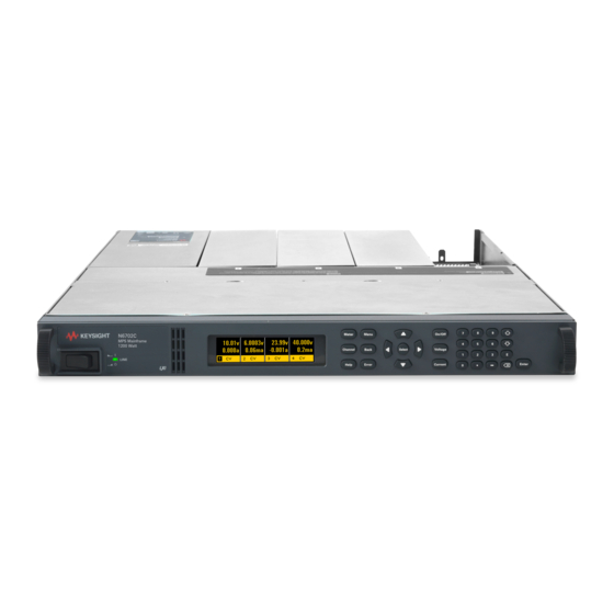
Page 1: Power System
Keysight Series N6700 Low-Profile Modular Power System User’s Guide... -
Page 2: Legal Notices
Keysight shall not be liable for errors or for those rights customarily provided to end incidental or consequential damages in user customers. Keysight provides this... -
Page 3: Safety Notices
Return the product to a Keysight Sales and Service Office for service and Before Applying Power Terminal is at earth repair to ensure that safety features are potential. - Page 4 In the United States: (800) 829-4444 In Europe: 31 20 547 2111 In Japan: 0120-421-345 Or use our Web link for information on contacting Keysight in your country or specific location: www.keysight.com/find/assist Or contact your Keysight Technologies Representative.
-
Page 5: Table Of Contents
Contents 1 – Quick Reference ....................... 7 The Keysight N6700 Modular Power System – At a Glance ... 8 The Front Panel – At a Glance ............11 The Rear Panel – At a Glance ............11 Front Panel Display – At a Glance ..........12 Front Panel Keys –... - Page 6 A – Specifications ......................99 Keysight N6700B, N6701A, N6702A MPS Mainframes ....100 B – Using the Digital Port ..................103 Digital Control Port ..............104 Configuring the Digital Control Port ..........105 C – Power Allocation ....................109 Power Limit Operation ..............110 Module Power Allocation .............
-
Page 7: Quick Reference
Quick Reference The Keysight N6700 Modular Power System – At a Glance ... 8 The Front Panel – At a Glance ............11 The Rear Panel – At a Glance ............11 Front Panel Display – At a Glance ..........12 Front Panel Keys –... -
Page 8: Output Features
Quick Reference The Keysight N6700 Modular Power System – At a Glance The Keysight N6700 Modular Power System is a configurable, one rack- unit (1U) platform that lets you mix and match power modules to create a power system optimized for your test system requirements. -
Page 9: System Features
Each output has over-voltage, over-current, and over-temperature protection. Over-voltage and over-current protection are programmable. Multiple-Quadrant Available on Keysight N678xA SMU and N6783A power modules. 2- quadrant operation provides source and sink output capability. Keysight operation model N6784A offers 4- quadrant output operation. Measurement Features... -
Page 10: Model Differences
Option 2UA.is only available on Models N6761A and N6762A. It includes Option 761. Only available when using the remote interfaces; not from the front panel. List capability is not available on the negative current output on Model N6783A Keysight N6700 User’s Guide... -
Page 11: The Front Panel - At A Glance
SHOCK HAZARD The power cord provides a chassis ground through a WARNING third conductor. Be certain that your power outlet is of the three- conductor type with the correct pin connected to earth ground. Keysight N6700 User’s Guide... -
Page 12: Front Panel Display - At A Glance
Interface status Err = an error has occurred (press Error key to display error message) Lan = the LAN is connected and has been configured indicators IO = there is activity on one of the remote interfaces Keysight N6700 User’s Guide... -
Page 13: Front Panel Keys - At A Glance
The arrow keys increment or decrement the voltage or current settings. They are also used to select letters in alphabetic entry fields. The Enter key enters a value. If you exit a field without pressing the Enter key, the value is ignored. Keysight N6700 User’s Guide... -
Page 14: Front Panel Menu Reference
Enables/disables oscillation protection on Models N678xA SMU. Clear Clears output protection. Displays output state. States Reset Resets the instrument to its reset (*RST) state. SaveRecall Saves or recalls an instrument state. PowerOn Selects the power-on state: *RST, RCL0. Keysight N6700 User’s Guide... - Page 15 Nvram Resets all non-volatile RAM settings to their factory defaults. Password Changes the password for the admin functions. About Frame Displays model, serial number, and firmware revisions. Module Displays model, serial number, options, voltage, current, power. Keysight N6700 User’s Guide...
-
Page 16: Scpi Command Summary
Returns the total rms voltage (AC + DC) :HIGH? (@chanlist) Returns the high level of a voltage pulse :LOW? (@chanlist) Returns the low level of a voltage pulse :MAXimum? (@chanlist) Returns the maximum voltage :MINimum? (@chanlist) Returns the minimum voltage Keysight N6700 User’s Guide... - Page 17 Sets the mode for turn on/off transitions (N6761A, N6762A) :TMODe HIGHZ | LOWZ, (@chanlist) Specifies the turn-on/turn-off impedance (only on N678xA SMU) :INHibit :MODE LATChing | LIVE | OFF Sets the remote inhibit input :PON :STATe RST | RCL0 Programs the power-on state Keysight N6700 User’s Guide...
-
Page 18: Scpi Command Description
Sets the positive current limit (only on N678xA SMU, N6783A) :COUPle <Bool>, (@chanlist) Sets the current limit tracking state (only on N678xA SMU) :NEGative [:IMMediate][:AMPLitude] <NRf+>, (@chanlist) Sets the negative current limit (only on N678xA SMU, N6783A-BAT) Keysight N6700 User’s Guide... - Page 19 Generate a trigger output on the voltage or current step transient VOLTage [:LEVel] [:IMMediate][:AMPLitude] <NRf+>, (@chanlist) Sets the output voltage :TRIGgered [:AMPLitude] <NRf+>, (@chanlist) Sets the triggered output voltage :BWIDth LOW | HIGH1 | HIGH2 | HIGH3, (@chanlist) Sets the voltage bandwidth (only on N678xA SMU) Keysight N6700 User’s Guide...
- Page 20 :ACQuire (Acquire commands only on N676xA, N678xA SMU and Option 054) [:IMMediate] (@chanlist) Triggers the measurement immediately :CURRent [:LEVel] <NRf>, (@chanlist) Sets the current trigger level :SLOPe POSitive | NEGative, (@chanlist) Sets the current trigger slope Keysight N6700 User’s Guide...
-
Page 21: Common Commands
Return status byte *OPC Enable "operation complete" bit in ESR *TRG Trigger *OPT? Return option number *TST? Performs self-test, then returns result *RCL <NRf> Recalls a saved instrument state *WAI Waits until all device commands are done Keysight N6700 User’s Guide... - Page 22 TRIG:ACQ:VOLT:SLOP OUTP:COUP TRIG:ELOG:SOUR OUTP:DEL:FALL TRIG:TRAN:SOUR OUTP:DEL:RISE VOLT OUTP:PMOD VOLT VOLT:BWID OUTP:TMOD LOWZ VOLT:LIM OUTP:PROT:COUP VOLT:LIM:COUP OUTP:PROT:DEL 0.02 VOLT:LIM:NEG OUTP:PROT:OSC VOLT:MODE OUTP:PROT:WDOG VOLT:PROT:DEL OUTP:REL:POL NORM VOLT:PROT:REM POW:LIM VOLT:PROT:REM:NEG VOLT:RANG RES:STAT VOLT:SLEW 9.9E+37 SENS:CURR:CCOM VOLT:SLEW:MAX SENS:CURR:RANG [SOUR:]VOLT:TRIG SENS:CURR:RANG:AUTO Keysight N6700 User’s Guide...
-
Page 23: Installation
Before installing the instrument, check the list under “Items Supplied” and verify that you have received these items with your instrument. If anything is missing, please contact your nearest Keysight Sales and Support Office. -
Page 24: General Information
200 microampere measurement range with output disconnect relays. Only on Models N6761A, N6762A. Tracking overvoltage protection function. Only available on Models N6752A, N6754A, and N6762A when installed in an N6700B, N6701A, or N6702A mainframe. A small AC network is always present across the output terminals. Keysight N6700 User’s Guide... -
Page 25: Items Supplied
When you receive your power system, inspect it for any obvious damage that may have occurred during shipment. If there is damage, notify the shipping carrier and nearest Keysight Sales and Support Office immediately. Refer to www.keysight.com/find/assist. Until you have checked out the power system, save the shipping carton and packing materials in case the unit has to be returned. -
Page 26: Installing The Unit
3 and 4, it is assigned channel number 3. Grouped power modules, those that are connected in parallel and have been configured or grouped to act as a single higher-power channel, are assigned the channel number of the lowest numbered slot of the group. Keysight N6700 User’s Guide... -
Page 27: Power Module Installation
Installation Power Module Installation The information in this section applies if you have purchased an N6700 NOTE mainframe without the power modules installed, or if you are adding a power module to the mainframe. Turn the mainframe off and disconnect the power cord before installing or CAUTION removing power modules. -
Page 28: Rack Installation
Use Rack Mount kit (Option 908) to rack mount your instrument. The Rack Mount Kit is also available by ordering part number N6709A. Keysight N6700 MPS mainframes can be mounted in a 19-inch EIA rack cabinet. They are designed to fit in one rack-unit (1U) of space. Do not block the air intake and exhaust at the sides of the unit, or the exhaust at the rear of the unit. - Page 29 Refer to the Service Guide for installation instructions. Power Factor Refer to Appendix A for power factor statistics at 400 Hz operation. Keysight N6700 User’s Guide...
-
Page 30: Connecting The Line Cord
100 VAC to 240 VAC. The frequency can be 50 Hz, 60 Hz, or 400 Hz. Keysight N6702A Mainframe Note: Standard AC mains circuits rated at nominal 100-120 VAC cannot supply enough current to power the N6702A mainframe when it is operated at its full rated power. -
Page 31: Connecting The Outputs
LOCKING LOCKING + +S G -S SCREW SCREW SENSE +S +LS -LS -S INSERT SENSE JUMPERS WIRES INSTALLED FOR LOCAL SENSING INSERT WIRES SENSE JUMPERS TWIST INSTALLED TWIST LEADS LEADS FOR LOCAL SENSING LOAD LOAD LOAD Keysight N6700 User’s Guide... -
Page 32: Wire Size
(refer to the table below). To satisfy safety requirements, load wires must be heavy enough not to overheat while carrying the short-circuit output current of the unit. Keysight Model N678xA SMU wiring requirements are described on the following page. - Page 33 Keysight N678xA SMU Wiring Requirements Because of the effect of wire inductance, the wire length information NOTE given in the previous table does not apply to Keysight Models N678xA SMU. To minimize the effect of wire inductance, the following table describes the allowable load lead and wire length for several common output wire types.
- Page 34 1 μA and greater. As shown below, cable guards are available at the output connector of Keysight Models N678xA SMU. The guard is typically used to drive the shields of cables and test fixtures. It provides a buffered voltage that is at the same potential as the + output terminals of the module connector.
-
Page 35: Multiple Loads
Keep each pair of wires as short as possible and twist or bundle them to reduce lead inductance and noise pickup. Note that Keysight Models N678xA SMU have additional wiring restrictions as discussed under “Keysight N678xA SMU Wiring Requirements”. -
Page 36: Remote Sense Connections
0.5Ω per lead (this requires 20 AWG or heavier for a 50 foot length). Note that Keysight Models N678xA SMU require remote sensing when using any of the High output bandwidth modes discussed in Chapter 4. -
Page 37: Open Sense Leads
OVP circuit could be higher than the voltage being regulated at the load. Note that for Keysight Models N678xA SMU only, the OVP circuit senses at the 4-wire sense terminals rather than at the output terminals. This allows for more precise overvoltage monitoring directly at the load. -
Page 38: Parallel Connections
Only connect outputs that have identical voltage and current ratings in parallel. CAUTION Keysight Models N678xA SMU may be paralleled, but ONLY when operated in Current Priority mode. Voltage Priority operation is not allowed. Connecting outputs in parallel provides a greater current capability than can be obtained from a single output. - Page 39 CV load effect, CV load cross regulation, CV source effect, and CV short term drift. These are all twice the voltage programming accuracy (including the percentage portion) at all operating points. Load transient specifications are typically twice the single output. Load Transient Recovery Time Keysight N6700 User’s Guide...
-
Page 40: Series Connections
240 VDC from chassis ground. Only connect outputs that have identical voltage and current ratings in CAUTION series. Keysight Models N678xA SMU and N6783A–x cannot be connected in series. To prevent currents from damaging the power system when the load is connected, always turn series-connected outputs on and off together. - Page 41 CC load effect, CC load cross regulation, CC source effect, and CC short term drift. These are twice the current programming accuracy (including the percentage portion) at all operating points. Load Transient Load transient specifications are typically twice the single output. Recovery Time Keysight N6700 User’s Guide...
-
Page 42: Positive And Negative Voltages
The instrument can be operated with any output terminal ± 240 VDC including output voltage from ground. Keysight Models N678xA SMU are optimized for grounding the negative NOTE output terminal. Grounding the positive terminal may result in increased current measurement noise and a reduction in current measurement accuracy. - Page 43 AC line switch: Install a ferrite core (Keysight p/n 9170-2131) on the power cord to insert additional impedance in the current path. This ferrite core is now installed inside N6701A and N6702A mainframes.
-
Page 44: Connecting The Auxiliary Voltage Measurement Input
This information only applies to Keysight Models N6781A and N6785A. The auxiliary voltage measurement input is located on the rear panel of the Keysight N6781A and N6785A. It is primarily used for battery voltage rundown measurements, but it is also suitable for general purpose DC measurements. -
Page 45: Getting Started
Detailed information on configuring the remote interfaces is included in NOTE the Keysight Technologies USB/LAN/GPIB Interfaces Connectivity Guide, which is available on the Automation-Ready CD included with this product... -
Page 46: Turning The Unit On
Then press Enter. If you make a mistake, either use the backspace key to delete the NOTE number, press Back to back out of the menu, or press Meter to return to meter mode. Keysight N6700 User’s Guide... -
Page 47: Entering A Current Limit Setting
The status indicator next to the channel number indicates the output’s status. In this case, the output channel is in constant voltage mode. For a description of the status indicators, refer to Chapter 1, under NOTE “Front Panel Display – At a Glance”. Keysight N6700 User’s Guide... -
Page 48: Using The Front Panel Menu
The menu path now shows that the commands shown on the second line are located under the Protect command. The OVP command is highlighted. The third line indicates which functions are located under the OVP command. Press Sel to select the OVP command. Keysight N6700 User’s Guide... -
Page 49: In Case Of Trouble
The front panel Err indicator comes on if self-test fails or if other operating problems occur with your instrument. Press the Error key to display the list of errors. Refer to the N6700 Service Guide for further information. The N6700 Service Guide is included as part of the optional Manual Set (Option 0L1). -
Page 50: Connecting To The Interfaces
Getting Started Connecting to the Interfaces The Keysight N6700 MPS supports GPIB, LAN, and USB interfaces. All three interfaces are live at power-on. Connect your interface cable to the appropriate interface connector. Information on configuring the interfaces is found later in this chapter. - Page 51 USB-enabled instrument to the Universal Serial Bus (USB). The following figure illustrates a typical USB interface system. If you have not already done so, install the Keysight IO Libraries Suite from the Automation-Ready CD that is shipped with your product.
- Page 52 Use the Connection Expert utility of the Keysight IO Libraries Suite to add the N6700 power system and verify a connection. To add the instrument, you can request the Connection Expert to discover the instrument. If the instrument cannot be found, add the instrument using the instrument’s hostname or IP address.
- Page 53 Use the Connection Expert utility of the Keysight IO Libraries Suite to add the N6700 power system and verify a connection. To add the instrument, you can request the Connection Expert to discover the instrument. If the instrument cannot be found, add the instrument using the instrument’s hostname or IP address.
- Page 54 This value is the IP Address of the default gateway that allows the Gateway instrument to communicate with systems that are not on the local subnet, as determined by the subnet mask setting. A value of 0.0.0.0 indicates that no default gateway is defined. Keysight N6700 User’s Guide...
- Page 55 DNS server specific DNS server. DNS Server This value is the address of the DNS server. It is used if you are not using DHCP or if you need to connect to a specific DNS server. Keysight N6700 User’s Guide...
- Page 56 Smaller keepalive time-out values will generate more keepalive probes (network traffic), using more of the available network bandwidth. Allowed values: 720 - 99999 seconds. Reset Resets the LAN settings to the factory-shipped state. These settings are listed at the end of this chapter. Keysight N6700 User’s Guide...
-
Page 57: Communicating Over The Lan
Getting Started Communicating Over the LAN The Keysight IO Libraries Suite along with instrument drivers for specific programming environments can be used to communicate with your power system. You can also communicate with your power system using its built-in Web server, the Telnet utility, or sockets. These latter methods are a convenient way to communicate with the power system without using I/O libraries or drivers. -
Page 58: Using Telnet
Using Telnet In an MS-DOS Command Prompt box type: telnet hostname 5024 where hostname is the N6700 hostname or IP address, and 5024 is the instrument’s telnet port. You should get a Telnet session box with a title indicating that you are connected to the power system. -
Page 59: Securing The Interfaces
These factory-shipped LAN settings can be restored by selecting the Reset control in the System\IO\LAN\Config\Reset menu. All non-volatile settings including LAN, can be restored by selecting the Reset control located in the System\Admin\Nvram menu. Keysight N6700 User’s Guide... - Page 60 Positive Screen saver Enabled Front panel lockout Disabled Screen saver delay 60 minutes Front panel meter view 1-channel USB interface Enabled GPIB Address Wake on I/O Enabled Key clicks Enabled Web server Enabled LAN interface Enabled Keysight N6700 User’s Guide...
-
Page 61: Operating The Power System
For complete details on the SCPI (Standard Commands for Programmable Instruments) commands, refer to the Programmer’s Reference Help file included on the Keysight N6700 Product Reference CD. This CD-ROM is shipped along with your instrument. The simple examples discussed in this chapter show you how to... -
Page 62: Programming The Output
Select. VOLT:RANG 5,(@1) For Keysight Models N678xA SMU operating in current priority mode, you can specify a Voltage limit., which limits the output voltage at the specified value. In current priority mode, the output current remains at its programmed setting as long as the output voltage is within the positive or negative limit. - Page 63 Set the Output Mode NOTE This information applies to Keysight Models N678xA SMU only. For Keysight Models N678xA SMU, you can select either Voltage priority or Current priority mode. In voltage priority mode the output is controlled by a bi-polar constant voltage feedback loop, which maintains the output voltage at its positive or negative programmed setting.
- Page 64 For other ranges the minimum slew rate is proportional to the full scale range. The current slew rate control is only available on Keysight Models N678xA SMU. It determines the rate at which the current changes to a new programmed setting.
- Page 65 The relays are only opened or closed when the output is at a safe state (zero voltage; zero current). Note however, that you can program the output state on or off while leaving the relay state unchanged. Keysight N6700 User’s Guide...
- Page 66 10.001V Set the Output Resistance NOTE This information applies to Keysight Models N6781A and N6785A only. Output resistance programming is primarily used in battery testing applications, and only applies in Voltage priority mode. Values are programmed in Ohms, from – 40 mΩ to + 1 Ω.
- Page 67 7–150 μF Remote only 6 inches (155 mm) 50 to 200 mΩ See Chapter 2 under “Keysight N678xA SMU Wiring Requirements” for additional information on allowable load lead lengths. Connecting capacitive loads that fall outside the indicated ranges may NOTE result in output instability or oscillation, and may cause the output to turn off, setting the OSC status bit.
-
Page 68: Synchronizing Output Steps
To set a voltage and current trigger level for output 1 use: Select the Trig Voltage box to set the voltage. Select the Trig VOLT:TRIG 15,(@1) Current box to set the current. CURR:TRIG 1,(@1) Enter a value and press Select. Keysight N6700 User’s Guide... - Page 69 Select the Transient\Control. To initiate the transient trigger system: Scroll to Initiate and press Select. INIT:TRAN (@1) It takes a few milliseconds for the instrument to be ready to receive a trigger signal after receiving the INITiate:TRANsient command. Keysight N6700 User’s Guide...
- Page 70 STAT:OPER:COND?(@1) If a bit value of 16 is returned in the query, the WTG_tran bit is true, and the instrument is ready to receive the trigger signal. Refer to the N6700 Programmer’s Reference Help file for more information. Unless INITiate:CONTinuous:TRANsient is programmed, it will be...
- Page 71 If a bit value of 64 is returned in the query, the TRAN_active bit is true, and the transient action is NOT complete. When the TRAN_active bit is false, the transient action is complete. Refer to the N6700 Programmer’s Reference Help file for more information.
-
Page 72: Programming Output Lists
The List Function Either output voltage or output current or both, may be list-controlled. For Keysight Models N678xA SMU, only the parameters associated with one of the priority modes (either voltage priority or current priority) may be list controlled. List mode lets you generate complex sequences of output changes with rapid, precise timing, which may be synchronized with internal or external signals. - Page 73 To program output 1, use Select List Step 1 and enter a LIST:VOLT 15,0, (@1) voltage value of 0. Press Select. LIST:DWEL 1,2, (@1) Enter a dwell value of 2 for List Step 1 and Press Select. Keysight N6700 User’s Guide...
- Page 74 Select the Transient\Control. To program output 1, use Select Initiate and Press Select. INIT:TRAN (@1) Step 10. Trigger the output pulse or pulse train. Front Panel: SCPI Command: Select Transient\Control. *TRG Select Trigger and Press Select. Keysight N6700 User’s Guide...
- Page 75 Step 4. Determine how the list is paced. To pace the list by dwell time, set the list pacing to Dwell-paced on the front panel menu. (Set the LIST:STEP command to AUTO.) As each dwell time elapses, the next step is immediately output. Keysight N6700 User’s Guide...
- Page 76 2 times, use Enter the number of list repetitions (2) and Press Select. LIST:COUN 2, (@1) Step 8. Select a trigger source, initiate, and trigger the list. This is described in detail under "Synchronizing Output Steps". Keysight N6700 User’s Guide...
-
Page 77: Making Measurements
Seamless Measurements Seamless voltage and current measurement autoranging is available on Keysight Models N6781A, N6782A, N6785A, and N6786A. This enables a wide dynamic measurement range with no data lost across ranges. Autoranging does not include the 10 μA range, which must be selected manually. - Page 78 FETC:VOLT? (@1) FETC:CURR? (@1) Auxiliary Voltage Measurements Keysight Models N6781A and N6785A have an auxiliary voltage measurement input, whose primary use is for battery voltage rundown measurements. It may also be suitable for other applications including general purpose DC voltage measurements between +/-20 VDC. The auxiliary voltage measurement input is isolated from other commons.
-
Page 79: Using The Digitizer
Select Measure\Range. To set the 5 V measurement range: Select the lower measurement SENS:VOLT:RANG 5, (@1) To set the 1 A measurement range: range from the voltage or current dropdown menu. Then SENS:CURR:RANG 1, (@1) press Select. Keysight N6700 User’s Guide... - Page 80 Seamless Measurements Seamless voltage and current measurement autoranging is available on Keysight Models N6781A, N6782A, N6785A, and N6786A. This enables a wide dynamic measurement range with no data lost across ranges. Autoranging does not include the 10 μA range, which must be selected manually.
- Page 81 The following commands trigger and return measurement data.: Front Panel: SCPI Command: Select the Meter key. Front To measure average voltage & panel meters can only measure current: average voltage and current. MEAS:VOLT?(@1) MEAS:CURR?(@1) To measure RMS voltage & current: MEAS:VOLT:ACDC?(@1) MEAS:CURR:ACDC?(@1) Keysight N6700 User’s Guide...
- Page 82 This may tie up the computer if the measurement trigger does not occur immediately. You can test the MEAS_active bit in the operation status register to know when the measurement has completed as explained in the following section. Keysight N6700 User’s Guide...
- Page 83 This allows pre- or post-trigger data sampling. 524,288 DATA POINTS OFFSET = -524,287 524,288 DATA POINTS OFFSET = -262,144 524,288 DATA POINTS OFFSET = 0 OFFSET = 0 to 2E9 524,288 DATA POINTS TIME TRIGGER Keysight N6700 User’s Guide...
- Page 84 To select Bus triggers for output 1: TRIG:ACQ:SOUR BUS,(@1) To select a Digital pin as the trigger: TRIG:ACQ:SOUR PIN<n>,(@1) To select a Transient output as trigger: TRIG:ACQ:SOUR TRAN<n>,(@1) where n is the output channel that will generate the trigger signal. Keysight N6700 User’s Guide...
- Page 85 To query the WTG_meas bit (bit 3): STAT:OPER:COND?(@1) If a bit value of 8 is returned in the query, the WTG_meas bit is true, and the instrument is ready to receive the trigger signal. Refer to the N6700 Programmer’s Reference Help file for more information. NOTE It will be necessary to initiate the measurement trigger system each time a triggered measurement is desired.
- Page 86 If a bit value of 32 is returned in the query, the MEAS_active bit is true, and the measurement is NOT complete. When the MEAS_active bit is false, you can retrieve the measurement. Refer to the N6700 Programmer’s Reference Help file for more information.
-
Page 87: Using The Protection Functions
Over-voltage protection is a hardware OVP whose trip level is a programmable value. The OVP is always enabled. OV− Negative voltage protection is a hardware OVP. Only applies to Keysight N678xA SMU and N6783A. Over-current protection is a programmable function that can be enabled or disabled. - Page 88 Then press Select. VOLT:PROT:TRAC:OFFS 2,(@1) Keysight Models N678xA SMU also have a back-up local OVP function. Refer to “Over-voltage Protection” in chapter 2 for a description of the feature. Additionally, for Keysight Model N6784A, you can program a negative over- voltage value.
- Page 89 60 seconds after all IO activity has ceased. The watchdog state and delay settings are volatile, but can be saved and recalled as part of the instrument state. A watchdog protect can be cleared as described under “Clear Output Protection Functions”. Keysight N6700 User’s Guide...
- Page 90 OUTP:PROT:WDOG:DEL 600 Set the Oscillation Protection NOTE This information applies to Keysight Models N678xA SMU only. If open sense leads or capacitive loads outside the allowable range cause the output to oscillate, the oscillation protection function detects the oscillation and latches the output off. The condition is annunciated on the front panel by the OSC status annunciator.
-
Page 91: External Data Logging
Select the Measurement Functions and Ranges The following commands select a measurement function: Front Panel: SCPI Command: Not Available To enable voltage or current measurements: SENS:ELOG:FUNC:VOLT ON,(@1) SENS:ELOG:FUNC:CURR ON,(@1) To enable min/max measurements: SENS:ELOG:FUNC:VOLT:MINM ON,(@1) SENS:ELOG:FUNC:CURR:MINM ON,(@1) Keysight N6700 User’s Guide... - Page 92 Seamless Measurements Seamless voltage and current measurement autoranging is available on Keysight Models N6781A, N6782A, N6785A, and N6786A. This enables a wide dynamic measurement range with no data lost across ranges. Autoranging does not include the 10 μA range, which must be selected manually.
- Page 93 Trigger Input to be used as a trigger source (see Appendix C). Use the following commands to select one of the available trigger sources: Front Panel: SCPI Command: Not Available TRIG:ELOG:SOUR BUS,(@1) TRIG:ELOG:SOUR IMM,(@1) TRIG:ELOG:SOUR EXT,(@1) TRIG:ELOG:SOUR PIN<n>,(@1) Keysight N6700 User’s Guide...
- Page 94 The data for each channel is a definite length binary block, with the byte order specified by the FORMat:BORDer command. Terminate the Measurement Front Panel: SCPI Command: Not Available To abort the external data logger: ABOR :ELOG (@1) Keysight N6700 User’s Guide...
-
Page 95: Instrument Identification
Cycle AC power. *TST? Instrument Identification For Keysight N6700 mainframes, you can return the model number, serial number, firmware revision, backup and active firmware. For power modules, you can return the model number, serial number, installed options, voltage, current and power rating. - Page 96 Operating the Power System Output Groups NOTE Output grouping does not apply to Keysight Models N678xA SMU. Output channels can be configured or “grouped” to create a single output with higher current and power capability. Almost all instrument functionality is supported by grouped channels, including voltage and current programming, measurements, status, step and list transients.
- Page 97 If the password is lost, the SYSTem:PASSword:FPANel:RESet command NOTE can reset the front panel lockout password. Refer to the Programmer’s Reference Help file on your Keysight N6700 Product Reference CD for more information. The SYSTem:COMMunicate:RLSTate RWLock command can also lock and unlock the front panel.
-
Page 98: Front Panel Display
You can specify how the output channels are displayed at turn on. Front Panel: SCPI Command: Select System\Preferences\Display\View To display all channels: DISP:VIEW METER4 Check 1-channel to display channel one. Check 4-channel to display all channels. Keysight N6700 User’s Guide... -
Page 99: Specifications
Keysight N6700 Modular Power System Family Specifications Guide. This document is available on the Keysight N6700 Product Reference CD that is shipped along with your instrument as well as on the web at www.keysight.com/find/N6700. -
Page 100: Keysight N6700B, N6701A, N6702A Mps Mainframes
LXI Compliance Class C (only applies to units with LXI label on front panel) USB 2.0 Requires Keysight IO Library version M.01.01 or 14.0 and up 10/100 LAN Requires Keysight IO Library version L.01.01 or 14.0 and up Built-in Web server... - Page 101 Refer to the outline diagrams on the following page. Under full load at 400 Hz, power factor drops from 0.99 @ 120 VAC to as low as 0.76 @ 265 VAC. Power factor degrades further under no load conditions. Keysight N6700 User’s Guide...
-
Page 102: Outline Diagram
Appendix A Specifications Outline Diagram Keysight N6700 User’s Guide... -
Page 103: B - Using The Digital Port
Inhibit Input Output State (see Appendix D) Earlier Keysight N6700A mainframes use a 4-pin connector instead of NOTE the 8-pin connector available on the N6700B, N6701A, and N6702A mainframes. Refer to the Service Guide for information on pin... -
Page 104: Digital Control Port
When Negative polarity is selected, a logical true signal is a voltage low at the pin. For a complete description of the electrical characteristics of the digital port, see Appendix A. Keysight N6700 User’s Guide... -
Page 105: Configuring The Digital Control Port
Digital Output Pins 1 - 7 TTL, AS, CMOS, HC Relay driver Pins 1 - 7 (contain internal clamp diodes for inductive flyback) Digital Input Pins 1 - 7 A) Relay Circuits B) Digital Interface Circuits Keysight N6700 User’s Guide... - Page 106 In the Function field, select either DIG:PIN1:FUNC TOUT To select the trigger input Trig In or Trig Out. function for pin 2: In the Polarity field, select either DIG:PIN2:FUNC TINP Positive or Negative. To select the trigger polarity: DIG:PIN<1-7>:POL <pol> Keysight N6700 User’s Guide...
- Page 107 To latch the Inhibit signal: Negative. OUTP:INH:MODE LATC Select Protect\Inhibit. To set the Inhibit signal live: Select either Latching or Live. OUTP:INH:MODE LIVE To disable the Inhibit signal, To disable the Inhibit signal: select Off OUTP:INH:MODE OFF Keysight N6700 User’s Guide...
- Page 108 Output State Only pins 4 through 7 can be configured to control the output state. This function lets you connect multiple Keysight N6700 mainframes together and synchronize the output on/off sequence across mainframes. Refer to Appendix D for detailed information.
-
Page 109: C - Power Allocation
However, it is possible to configure a power system in which the combined ratings of the power modules exceed the power rating of the mainframe. The power rating of Keysight N6700 mainframes is as follows: Keysight N6700A/B = 400 W ... -
Page 110: Power Limit Operation
- either constant voltage or constant current mode. Power limiting should not be used when Keysight N673xB, N674xB, and NOTE N677xA power modules are grouped. When these power modules are grouped, you must reset the power limit to its maximum rated value. -
Page 111: Module Power Allocation
AC power or send the following commands: Front Panel: SCPI Command: Select States\Reset *RST POW:LIM MAX,(@1:4) When an output channel is set to MAX, it returns to its maximum rated NOTE value, and the power limit function will not activate. Keysight N6700 User’s Guide... -
Page 113: D - Output On/Off Synchronization
Off command is received. For complete details on the SCPI commands discussed in this appendix, refer to the N6700 Programmer’s Reference Help file included on the Keysight N6700 Product Reference CD. This CD-ROM is shipped along with your instrument. -
Page 114: Synchronizing Output Turn-On Delays
Output On/Off Synchronization Synchronizing Output Turn-on Delays All N6700 Power Modules that are installed in a Keysight N6700 mainframe exhibit a minimum delay offset that applies from the time that a command to turn on the output is received until the output actually turns on. - Page 115 Output turn-on synchronization must be enabled on the mainframe. Front Panel: SCPI Command: In the front panel menu, select To enable, send: Output\Sequence\Couple. OUTP:COUP ON Check the box labeled “Enable”. To disable, send: To disable, uncheck the box. OUTP:COUP OFF Keysight N6700 User’s Guide...
- Page 116 There is no need to specify a delay offset when outputs turn off. Outputs NOTE start executing their turn-off delays as soon as an output Off command is received. Keysight N6700 User’s Guide...
-
Page 117: Synchronizing Multiple Mainframes
In this example, pin 6 will be configured as the output On control. Pin 7 will be configured as the output Off control. The ground or Common pins also need to be connected together. Keysight N6700 User’s Guide... -
Page 118: Operation
If a mainframe has its ON/OFF key coupled (located in the System\Preferences\Keys menu), turning the output on or off on any coupled channel will cause all coupled channels as well as non-coupled channels on that mainframe to turn on or off. Keysight N6700 User’s Guide... -
Page 119: E - Source Operating Modes
Appendix E Source Operating Modes Single Quadrant Operation ............120 Keysight N678xA Multi-Quadrant Operation ......122 This appendix discusses the difference between constant voltage and constant current operating modes, multiple output quadrant operation, and other advanced source functions. -
Page 120: Single Quadrant Operation
Appendix E Source Operating Modes Single Quadrant Operation The Keysight N6700 Modular Power System can operate in either constant voltage (CV) or constant current (CC) over the rated output voltage and current. Constant voltage mode is defined as an operating... - Page 121 The following figure illustrates the autoranging output characteristic of the Keysight N675xA and N676xA power modules. Point 3 shows a situation in which the voltage and current settings are such that the operating locus is limited by the maximum output power boundary of the output.
-
Page 122: Keysight N678Xa Multi-Quadrant Operation
Appendix E Source Operating Modes Keysight N678xA Multi-Quadrant Operation Keysight Models N678xA SMU can be operated in either voltage or current priority mode. They can source as well as sink output power. Note that Keysight Models N6781A, N6782A, N6785A, and N6786A operate only in the + Voltage quadrants. - Page 123 +V limit I setting -8 A -3 A -1 A + Current +8 A +3 A +1 A − Voltage -V limit operation applies to N6784A only -20 V -6 V Sourcing power Sinking power Programmable Keysight N6700 User’s Guide...
- Page 124 Once the current is exceeds 112% of the rated current of the range, the output will shut down, the output relays will open, and the OC and PROT status bits will be set. Keysight N6700 User’s Guide...
- Page 125 Index data socket ............58 DCL ..............58 Declaration of conformity ........2 Admin menu, password ........59 default gateway ........... 55 airflow ........... 26, 29, 102 digital I/O All ................ 64 configuring............. 105 allocation, power ..........110 connections ........... 105 autoranging ............
- Page 126 ....... 80, 91 generate ............70 measurement features.......... 9 initiate .............. 69 measurement trigger level..............68 generate ............85 source .............. 69 initiate ............. 84 outputs in parallel ..........39 source .............. 83 outputs in series ..........41 Keysight N6700 User’s Guide...
- Page 127 ............26 watchdog timer ........... 88 sample interval ..........80, 91 Web server ............57 SCPI Web URL’s ............. 4 common commands ........21 wire sizes ............. 32 subsystem commands ........16 screen saver ............97 Keysight N6700 User’s Guide...
- Page 128 Appendix E Source Operating Modes This information is subject to change without notice. © Keysight Technologies 2006 - 2015 Edition 8, January 2015 *5969-2937* 5969-2937 www.keysight.com Keysight N6700 User’s Guide...
Need help?
Do you have a question about the N6700 and is the answer not in the manual?
Questions and answers
What are the limits to constant Voltage that trigger UNR output condition?Are the limits adjustable?