Table of Contents
Advertisement
Quick Links
Vision™ OPLC™
This guide provides basic information for Unitronics' controllers V560-T25B.
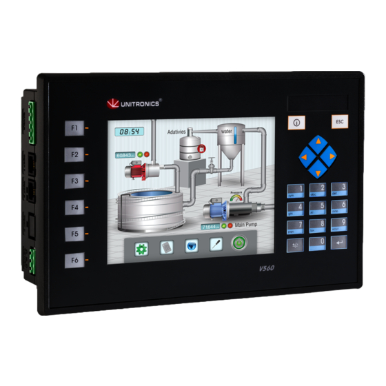
General Description
V560 OPLCs are programmable logic controllers that comprise a built-in operating panel containing a
5.7" Color Touchscreen. The V560 offers an alpha-numeric keypad with function keys as well as a
virtual keyboard. Either may be used when the application requires the operator to enter data.
Communications
I/O Options
Information Mode
Programming
Software,
& Utilities
Unitronics
2 isolated RS232/RS485 ports
Isolated CANbus port
The user can order and install an Ethernet port
Communication Function Blocks include: SMS, GPRS, MODBUS
serial/IP Protocol FB enables PLC to communicate with almost any
external device, via serial or Ethernet communications
V560 supports digital, high-speed,
analog, weight and temperature
measurement I/Os via:
Snap-in I/O Modules
Plug into the back of the
controller to provide an on-
board I/O configuration
I/O Expansion Modules
Local or remote I/Os may be
added via expansion port or
Installation instructions and other data may be found in the module's technical
specification sheet.
This mode enables you to:
Calibrate the touchscreen
View & Edit operand values, COM port settings, RTC and screen
contrast/brightness settings
Stop, initialize, and reset the PLC
To enter Information Mode, press the <i> button, or press the touchscreen and
maintain contact for several seconds.
The Unitronics Setup CD contains VisiLogic software and other utilities
VisiLogic
Easily configure hardware and write both HMI and Ladder control
applications; the Function Block library simplifies complex tasks
such as PID. Write your application, and then download it to the
controller via the programming cable included in the kit.
Utilities
These include UniOPC server, Remote Access for remote
programming and diagnostics, and DataXport for run-time data
logging.
To learn how to use and program the controller, as well as use utilities such as
Remote Access, refer to the VisiLogic Help system.
Installation Guide
V560-T25B
1
Advertisement
Table of Contents

Related Manuals for Unitronics Vision OPLC V560-T25B


Summary of Contents for Unitronics Vision OPLC V560-T25B
- Page 1 Stop, initialize, and reset the PLC To enter Information Mode, press the <i> button, or press the touchscreen and maintain contact for several seconds. Programming The Unitronics Setup CD contains VisiLogic software and other utilities Software, VisiLogic & Utilities Easily configure hardware and write both HMI and Ladder control applications;...
- Page 2 All examples and diagrams are intended to aid understanding, and do not guarantee operation. Unitronics accepts no responsibility for actual use of this product based on these examples. Please dispose of this product according to local and national standards and regulations.
- Page 3 2. Insert the battery, ensuring that the polarity symbol on the battery is: - facing up - aligned with the symbol on the holder 3. Replace the battery cover. Mounting Dimensions Note that the LCD screen may have a single pixel that is permanently either black or white. Unitronics...
- Page 4 4. Tighten the bracket screws against the panel. Hold the bracket securely against the unit while tightening the screw. 5. When properly mounted, the controller is squarely situated in the panel cut-out as shown below. Unitronics...
- Page 5 Mounting the controller on a metal panel. Connect the functional earth terminal of the OPLC, and the common and ground lines of I/Os, directly to the earth ground of your system. For ground wiring, use the shortest and thickest possible wire. Unitronics...
- Page 6 RS232/RS485: DIP Switch Settings The settings below are for each COM port. Switch Settings RS232* RS485 RS485 with termination** *Default factory setting **Causes the unit to function as an end unit in an RS485 network Unitronics...
- Page 7 1. Line the circular guidelines on the controller up with the guidelines on the Snap-in I/O Module as shown below. 2 Apply even pressure on all 4 corners until you hear a distinct ‘click’. The module is now installed. Check that all sides and corners are correctly aligned. Unitronics...
- Page 8 CANbus Connector The information in this document reflects products at the date of printing. Unitronics reserves the right, subject to all applicable laws, at any time, at its sole discretion, and without notice, to discontinue or change the features, designs, materials and other specifications of its products, and to either permanently or temporarily withdraw any of the forgoing from the market.
Need help?
Do you have a question about the Vision OPLC V560-T25B and is the answer not in the manual?
Questions and answers