
Subscribe to Our Youtube Channel
Related Manuals for Meler SF10


Summary of Contents for Meler SF10
- Page 1 GLUING SOLUTIONS ADHESIVE INSTRUCTIONS MANUAL MELTER SF10 & SF20 RANGE MA-5199-ENG 241120...
- Page 2 Published by: Focke Meler Gluing Solutions, S.A. Pol. Arazuri-Orkoien, c/B, nº3 A E-31170 Arazuri - Navarra - Spain Phone: +34 948 351 110 info@meler.eu - www.meler.eu Focke Group Edition october 2020 © Copyright by Focke Meler All rights reserved. Its reproduction, diffusion or use by electronic or other means of all or any part of this document without the express authorization of its owner is strictly prohibited.
-
Page 3: Table Of Contents
TABLE OF CONTENTS MA-5199-ENG SF10 & SF20 RANGE ADHESIVE MELTER TABLE OF CONTENTS 1. SAFETY GUIDELINES General Symbols Mechanical components Electrical components Hydraulic components Pneumatic components Thermal components Materials Noise emission declaration Intended use Limited use 2. INTRODUCTION Description Modes of operation... - Page 4 Contents Mounting the equipment Electrical power connection 2-phases 200-240 VAC without neutral connection 3-phases 200-240 VAC without neutral connection 1-phase 120 VAC with neutral connection (SF10 120V) Hose and applicator connection Parameter Programming Programming working temperatures Selecting the overheating value...
- Page 5 TABLE OF CONTENTS MA-5199-ENG SF10 & SF20 RANGE ADHESIVE MELTER 4. MELTER OPERATION General information Filling the tank Starting up the melter equipment Melter equipment displays Displaying the temperature for each component Alarm displays Display and adjustment of the working speed...
- Page 6 FOCKE MELER GLUING SOLUTIONS TABLE OF CONTENTS Modes of operation 4-22 Mode of operation with internal pumping control and internal speed control 4-22 Mode of operation with internal pumping control and external speed control 4-23 Mode of operation with external pumping control and internal speed control...
- Page 7 TABLE OF CONTENTS MA-5199-ENG SF10 & SF20 RANGE ADHESIVE MELTER Pump maintenance Inspecting for leaks Gear motor maintenance Cleaning the motor fan Checking the lubricant Recommended lubricants Safety Thermostat 6. TECHNICAL CHARACTERISTICS Generals Dimensions 7. ELECTRICAL DRAWINGS 8. SPARE PARTS LIST A.
- Page 8 FOCKE MELER GLUING SOLUTIONS TABLE OF CONTENTS This page is intentionally left blank.
-
Page 9: Safety Guidelines
SAFETY GUIDELINES MA-5199-ENG SF10 & SF20 RANGE ADHESIVE MELTER 1. SAFETY GUIDELINES General The information contained in this section applies not only to everyday equipment operation, but also to any procedure carried out on it, whether for preventive maintenance or in the case of repairs and the replacement of worn out parts. -
Page 10: Mechanical Components
FOCKE MELER GLUING SOLUTIONS SAFETY GUIDELINES Mechanical components The hot-melt installation, which is installed to this device, requires moving parts that can cause damage. Use the equipment correctly, and do not remove the safety guards while the equipment is in operation; prevent the risk of possible entrapment due to moving mechanical parts. -
Page 11: Thermal Components
Safety Information Sheet of the adhesive. Materials Meler systems are designed for use with hot-melt adhesives. They should not be used with any other type of material, and especially not with solvents, which may cause personal injury or damage to internal system components. -
Page 12: Intended Use
Note: Do not modify the equipment or use components that were not supplied by Meler. For any modification of a component of the equipment or part of the installation, you must firstly consult the After-Sales Service... -
Page 13: Introduction
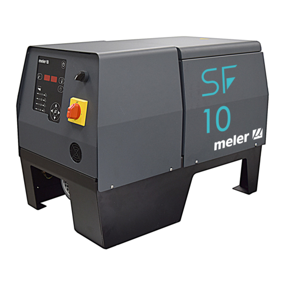
Most of the photographs and illustrations that appear in this manual refer to the SF10 melter. This model has been used as a reference for writing this manual as its main characteristics, with the exception of the tank capacity and the connection outputs are the same as those in the rest of the equipments of the serie. -
Page 14: Modes Of Operation
FOCKE MELER GLUING SOLUTIONS INTRODUCTION Modes of operation These melters may be used in all of the following modes: Work mode_ The hot-melt melter keeps materials hot at the pre- selected temperature indicated on the display. The pump is kept activated, waiting for the consumption command when one or more applicators are activated. -
Page 15: Main Components
INTRODUCTION MA-5199-ENG SF10 & SF20 RANGE ADHESIVE MELTER Main components 1. Front control card. 2. Access door to the electric area. 3. External pump switch. 4. Main switch ON/OFF. 5. Variable speed box connector. 6. Tank access lid. 7. Mechanical by-pass valve pressure control. -
Page 16: Control Card Components
FOCKE MELER GLUING SOLUTIONS INTRODUCTION Control card components 1. Tank indicator LED. 2. Applicator indicator LED. 3. Temperature set point. 4. Real temperature. 5. ON/OFF switch. 6. Standby function. 7. Temperature OK LED. 8. Time scheduling. 9. Left/right button - channel selection. -
Page 17: Pumping Control Card Components (Optional)
INTRODUCTION MA-5199-ENG SF10 & SF20 RANGE ADHESIVE MELTER Pumping control card components (optional) 1. Main switch ON/OFF. 2. External start-stop LED. 3. External speed control LED. 4. Pumping permission LED. 5. Up/down arrow keys for selecting values. 6. Left/right arrow keys for selecting options. -
Page 18: Sf Range
• SF10 and SF20 melters are prepared by default for the capacitive detector. • 240V SF10 and SF20 melters includes an adapter to connect it to 3 phases 230 without neutral. • 120V-30A and 120V-20A only available for SF10 model. -
Page 19: Installation
INSTALLATION MA-5199-ENG SF10 & SF20 RANGE ADHESIVE MELTER 3. INSTALLATION Warning: The melters are equipment with current technology and with certain foreseeable risks. Therefore, only allow qualified personnel with enough training and experience to use, install or repair this equipment. -
Page 20: Electrical Consumption
FOCKE MELER GLUING SOLUTIONS INSTALLATION Electrical connection Electrical connection Hoses connection Hoses connection Electrical Consumption In order to install a melter equipment os this serie, we should take into consideration the total consumption of the installation, including the consumption of the installed hoses and applicators. -
Page 21: Other Factors
Communicate any defect, even to the outer packing materials, to your Meler Representative or to the Main Office. Contents The equipment packing materials may contain accessories that form part of the same order. -
Page 22: Electrical Power Connection
FOCKE MELER GLUING SOLUTIONS INSTALLATION Electrical power connection SF10 and SF20 melters are designed to be connected to the electrical power supply in two possible ways, depending on the power of different elements connected: • 2-phases 200-240 VAC without neutral. -
Page 23: 3-Phases 200-240 Vac Without Neutral Connection
WITHOUT NEUTRAL L1 L2 L3 PE 3~230V 50/60Hz + PE 1-phase 120 VAC with neutral connection (SF10 120V) Connect each wire in the power cord to its corresponding place on the power intake connector. L1 N PE... -
Page 24: Hose And Applicator Connection
These series melters use standard Meler components. The entire range of Meler hoses and applicators may be connected to this equipment. Up to four hose-applicator outputs may be connected to SF10 and SF20 melters. SF10 and SF20 melters are equipped with a simple hydraulic distributor with four posibilities of hydraulic connection. -
Page 25: Parameter Programming
Once the melter and its components are installed, you will need to program the operational parameters appropriate for the specific application that will be performed. SF10 and SF20 simplify this task as much as possible, allowing the operator to modify only those parameters that are necessarily variable for each application. -
Page 26: Keeping A Component On Display
FOCKE MELER GLUING SOLUTIONS INSTALLATION 2. Using the right arrow, we advance to the next screen where the overheating symbol appears. 3. Select the desired value with the up-down arrow. The value displayed corresponds to the increase in real temperature over the set point temperature permitted without activating the alarm message. -
Page 27: External I/O Connections
INSTALLATION MA-5199-ENG SF10 & SF20 RANGE ADHESIVE MELTER External I/O connections The melter’s input and output signals (I/O) allow it to communicate with the main machine simply and directly. There are five signals that may be used to communicate with the main machine: •... -
Page 28: Temperature Ok
FOCKE MELER GLUING SOLUTIONS INSTALLATION Temperature ok 1. If only this signal will be connected, use a 0.5 mm two-wire cable. Install an electrical wall bushing Pg next to the electrical supply input. 2. Thread the electrical wire through the electrical wall bushing Pg and fasten it to the inside anchor, making sure that the cord reaches the terminal XTOK. -
Page 29: Low Level (Optional)
INSTALLATION MA-5199-ENG SF10 & SF20 RANGE ADHESIVE MELTER Low level (optional) 1. If only this signal will be connected, use a 0.5 mm two-wire cable. Install an electrical wall bushing Pg next to the electrical supply input. 2. Thread the electrical wire through the electrical wall bushing Pg and fasten it to the inside anchor, making sure that the cord reaches the terminal XLD. -
Page 30: Pumping External Permission
FOCKE MELER GLUING SOLUTIONS INSTALLATION When the switch is in the ‘OFF’ position, the corresponding channel does not heat unless activated from the outside, through a non-voltage contact between pin 1 (the common pin) and the pin that corresponds to the channel. -
Page 31: Variable Speed Box Optional Intallation
SF10 & SF20 RANGE ADHESIVE MELTER Variable speed box optional intallation SF10 and SF20 melters are prepared by default for being upgraded with an external electrical board for converting it into a variable speed melter. 1. Connect the box wire in the connector on the rear side of the melter. -
Page 32: Lay Out Pump Control Board
FOCKE MELER GLUING SOLUTIONS INSTALLATION Failures output in pump control card 1. If this is the only signal being connected, use 0.5 mm two-wire cable. Install an electrical wall bushing Pg next to the electrical supply input. 2. Thread the wire cable (max. Ø12.5mm) through the electrical wall bushing and fasten it to the inside anchor, making sure that the cord reaches the card connector. -
Page 33: Melter Operation
MELTER OPERATION MA-5199-ENG SF10 & SF20 RANGE ADHESIVE MELTER 4. MELTER OPERATION In this section we will introduce the method for using the melter. Although its operation is very simple, it should not be used by untrained personnel. Warning: Improper use may cause damage to the machine or injury and even death to the person using it. -
Page 34: Filling The Tank
FOCKE MELER GLUING SOLUTIONS MELTER OPERATION Filling the tank The tank may be equipped optionally with one capacitive detector. The capacitive detector issues a warning when the adhesive reaches the level, thanks to a low adhesive level external signal. Warning: Before refilling the tank, make sure that the adhesive is the same type as that already in the tank. -
Page 35: Melter Equipment Displays
MELTER OPERATION MA-5199-ENG SF10 & SF20 RANGE ADHESIVE MELTER One it has reached 3 °C (37.4 ºF) below the programmed temperature (set point) of the tank, a programmable delay timer starts until, guaranteeing fusion, the pump receives permission to operate and the signal will be sent to the main machine, indicated by the two corresponding (green) LEDs. -
Page 36: Displaying The Temperature For Each Component
FOCKE MELER GLUING SOLUTIONS MELTER OPERATION Displaying the temperature for each component The temperature may be displayed for each component (tank, distributor and each hose and applicator) by selecting the component with the cursor. Press the left-right arrow until the desired component is displayed. -
Page 37: Display And Adjustment Of The Working Speed
MELTER OPERATION MA-5199-ENG SF10 & SF20 RANGE ADHESIVE MELTER Actions Code Source Heating Pump Main machine signal Err 104 applicator2 overheating all components off Err 105 hose3 overheating all components off Err 106 applicator3 overheating all components off Err 107... -
Page 38: Temperature Adjustment
FOCKE MELER GLUING SOLUTIONS MELTER OPERATION Temperature adjustment The melters leave the factory with the following set point temperature values: • 160 °C (320 ºF) for the tank and distributor • 160 ºC (320 ºF) for the hoses and applicators •... -
Page 39: Programming The Applicator Parameters
MELTER OPERATION MA-5199-ENG SF10 & SF20 RANGE ADHESIVE MELTER Programming the applicator parameters The access to the parameters is performed from the special menu. Simulta- neously press the buttons with the clock symbol and the down arrow to enter this menu. The navigation order is as follows:... - Page 40 FOCKE MELER GLUING SOLUTIONS MELTER OPERATION 3. Use the right arrow to move to the next display where the overheating symbol appears. 4. Select the desired value (between 10 and 25 ºC / 50 and 77 ºF) using the up-down arrow.
- Page 41 MELTER OPERATION MA-5199-ENG SF10 & SF20 RANGE ADHESIVE MELTER 12. Use the up-down arrow to select the desired value (see ‘Timer to switch between ON - Standby - OFF modes’). 13. Use the right arrow to go to the next display.
- Page 42 FOCKE MELER GLUING SOLUTIONS MELTER OPERATION 18. Use the right arrow to go to the next display. 19. Use the up-down arrow to select the desired value (see ‘Counter that warns of the need to change the adhesive agent filter’).
-
Page 43: Timer To Switch Between On - Standby - Off Modes
MELTER OPERATION MA-5199-ENG SF10 & SF20 RANGE ADHESIVE MELTER Timer to switch between ON - Standby - OFF modes This function is used to program automatic switching from the ON mode to Standby mode after an inactive period of time (S-1) and from STANDBY mode to OFF mode after another waiting period (S-2) during which activity has not been resumed. -
Page 44: Password To Access Parameter Programming
FOCKE MELER GLUING SOLUTIONS MELTER OPERATION Password to access parameter programming A Password can be programmed to protect access to certain equipment pro- gramming functions by unauthorised users. The special menu can be used to program a value between 000 (disabled) and 999. -
Page 45: Counter That Warns Of The Need To Change The Adhesive Agent Filter
MELTER OPERATION MA-5199-ENG SF10 & SF20 RANGE ADHESIVE MELTER Counter that warns of the need to change the adhesive agent filter This function is a partial countdown counter that registers the hours of equi- pment operation, that is, with service temperature OK activated, from tP1000 hours to tP0000 hours. -
Page 46: Setting The Clock
FOCKE MELER GLUING SOLUTIONS MELTER OPERATION Setting the clock ‘SF’ series melters are equipped with a weekly programmable system contro- lling equipment connection and disconnection and activating and deactivating the standby function. Before programming these functions, it is necessary to introduce into the control unit data corresponding to the day and hour used to execute these programs. -
Page 47: Programming Equipment Activation/Deactivation
MELTER OPERATION MA-5199-ENG SF10 & SF20 RANGE ADHESIVE MELTER Programming equipment activation/deactivation You may program an activation and a deactivation time for every day of the week, from Monday (1) to Sunday (7). Time is expressed in 15 minute increments, so we cycle from 10.0 (10 hours and 0 minutes) to 10.1 (10 hours and 15 minutes) to 10.2 (10 hours and 30... -
Page 48: Disabling The Equipment Activation/Deactivation Program
FOCKE MELER GLUING SOLUTIONS MELTER OPERATION Disabling the equipment activation/deactivation program It is possible to disable the equipment activation/deactivation programming without canceling the daily programming. This way the programmed data is saved, but the programming will have no effect on the equipment. -
Page 49: Disabling The Equipment Standby Function Programming
MELTER OPERATION MA-5199-ENG SF10 & SF20 RANGE ADHESIVE MELTER Two times will appear, one in each display. The left display shows the start time, while the right display shows the finish time. 5. The blinking dot next to the start time indicates that this is the time that may be modified. -
Page 50: Special Function Buttons
FOCKE MELER GLUING SOLUTIONS MELTER OPERATION 4. Press the button with the clock symbol once again. The status will alternate each time you press the button. 5. Pressing either the left or the right arrow button will exit this program and return to the tank temperature display. -
Page 51: Pumping Control (Optional)
MELTER OPERATION MA-5199-ENG SF10 & SF20 RANGE ADHESIVE MELTER Pumping control (Optional) Starting up the pump control card The pump control card (hereingafter also control card), features an ON-OFF button that allows us to turn off the displays and LEDs (leaving on only the 24... -
Page 52: Password Security
FOCKE MELER GLUING SOLUTIONS MELTER OPERATION • Whenever an error occurs, the control disables pumping (red ON-OFF button LED is illuminated) and prevents the operation of the pump until the error is reset, the pumping ON-OFF button is pressed again and the red LED turns off. -
Page 53: Led Indicators
MELTER OPERATION MA-5199-ENG SF10 & SF20 RANGE ADHESIVE MELTER LED indicators Described below are the LED indicators on the pump control card to identify the status of the equipment: 1. Control card ON/OFF LED: when the external 24 Vdc power supply is present, this LED will always be illuminated;... -
Page 54: Modes Of Operation
FOCKE MELER GLUING SOLUTIONS MELTER OPERATION Modes of operation First of all, we must bear in mind that when password security is enabled and the control card is not manipulated during one minute, it is blocked and you need to enter the password. To prevent this from happening, password security may be disabled following the steps in the section ‘Password security’. -
Page 55: Mode Of Operation With Internal Pumping Control And External Speed Control
MELTER OPERATION MA-5199-ENG SF10 & SF20 RANGE ADHESIVE MELTER Mode of operation with internal pumping control and external speed control In this operating mode, pumping is controlled from the equipment and speed is controlled by a 0-10 V external signal from the main machine. -
Page 56: Mode Of Operation With External Pumping Control And Internal Speed Control
FOCKE MELER GLUING SOLUTIONS MELTER OPERATION Mode of operation with external pumping control and internal speed control In this operating mode, pumping is controlled from the main machine while speed is controlled from the equipment. Follow the steps below to use this operating mode: 1. -
Page 57: Mode Of Operation With External Pumping Control And External Speed Control
MELTER OPERATION MA-5199-ENG SF10 & SF20 RANGE ADHESIVE MELTER Mode of operation with external pumping control and external speed control In this working mode, both pumping and speed are controlled from the main machine. Follow the steps below to use this operating mode: 1. -
Page 58: User Configuration Menu
‘User configuration menu’, ‘1. MAXIMUM RPM’. The pump control card is designed with certain parameters programmed at Meler that can be modified if necessary to meet your requirements. Modifications may be made through the user configuration and programming speed ramp menus. -
Page 59: Displaying Alarms And Reset Function
MELTER OPERATION MA-5199-ENG SF10 & SF20 RANGE ADHESIVE MELTER Displaying alarms and reset function Maximum rpm alarm This alarm will be triggered when the motor rotates at a speed exceeding the MAXIMUM RPM ALARM value for the period established in the MAXIMUM RPM ALARM TIME field. -
Page 60: Configuring Speed Ramp
FOCKE MELER GLUING SOLUTIONS MELTER OPERATION Configuring speed ramp For equipment operating in external reference, the display will show the current pump rotation set point (input reference conversion as per the full scale and the conversion table). The conversion table may be programmed with up to 5 points (input voltage (V) and output speed (RPM)). -
Page 61: Programming Speed Ramp
MELTER OPERATION MA-5199-ENG SF10 & SF20 RANGE ADHESIVE MELTER Programming speed ramp To access this menu and program the different points corresponding to the voltage- speed ratio, you must select external reference (‘ref ext’ LED is illuminated) and press the right arrow key. Then the following message is displayed: The IN LED to the position ON and the OUT LED to the position OFF, 1 000, NOT EDITABLE;... -
Page 62: Current Vin Voltage Display
FOCKE MELER GLUING SOLUTIONS MELTER OPERATION Current Vin voltage display Whenever the Vin key is held pressed, the three digits on the right will show the input voltage reading to one decimal point. If the values for any point in the speed ramp table is being edited, and the Vin key is held pressed for 3 seconds, the voltage value which is operating at this time it will be copied to that value on the table. -
Page 63: Maintenance
MAINTENANCE MA-5199-ENG SF10 & SF20 RANGE ADHESIVE MELTER 5. MAINTENANCE Warning: The melter equipment is equipped with current technology, but has certain foreseeable risks. Therefore, only allow qualified personnel with enough training and experience to operate install or repair this equipment. -
Page 64: Removing Exterior Panels
FOCKE MELER GLUING SOLUTIONS MAINTENANCE Removing exterior panels 1. Turn off the melter. 2. To remove the electrical cabinet cover, remove the four screw as indicated (A), and slide it uptwards. 3. To remove the tank cover, remove the four screw as indicated (B), and slide it uptwards. -
Page 65: Access To The Electrical Connections Box Of The Gear-Motor
MAINTENANCE MA-5199-ENG SF10 & SF20 RANGE ADHESIVE MELTER Access to the electrical connections box of the gear-motor 1. Turn off the melter. 2. Remove the rear cover to access the electrical connections gear-motor box. Warning: Risk of electric shock. Carelessness may result in injury or death. -
Page 66: Filter Maintenance
FOCKE MELER GLUING SOLUTIONS MAINTENANCE Filter maintenance The melters are equipped with a 100 mesh pump filter. The filter prevents impurities and burnt adhesive remains from being pushed out from the tank by the pump. When the filter is removed from its housing, all the impurities remain inside so that the inside of the distributor stays perfectly clean. -
Page 67: Cleaning The Tank
MAINTENANCE MA-5199-ENG SF10 & SF20 RANGE ADHESIVE MELTER Cleaning the tank The hot-melt tank must be cleaned on occasion to maintain its fusion and anti-adherence properties. The tank is covered on the inside with PTFE and inclined enough to aid unloading the hot-melt and to avoid it from being retained inside when consequential burning occurs. -
Page 68: Emptying The Tank
FOCKE MELER GLUING SOLUTIONS MAINTENANCE Warning: Whenever you handle the filter or any other element subject to pressure, you must always perform a system depressurization first (see the corresponding section) Emptying the tank During normal maintenance activities, it is recommended, and sometimes necessary to empty the tank directly, without passing the adhesive through the pump system. -
Page 69: Gear Motor Maintenance
MAINTENANCE MA-5199-ENG SF10 & SF20 RANGE ADHESIVE MELTER 2. Retighten or remove the screws that hold the gasket in place. 3. Replace the gaskets and reassemble the parts. Occasionally, as a result of the system’s heating-cooling cycles, it may be necessary to retighten the screws. - Page 70 FOCKE MELER GLUING SOLUTIONS MAINTENANCE This page is intentionally left blank.
-
Page 71: Technical Characteristics
TECHNICAL CHARACTERISTICS MA-5199-ENG SF10 & SF20 RANGE ADHESIVE MELTER 6. TECHNICAL CHARACTERISTICS Generals 120V-30A Tank capacity 10 l / 2.64 gal 10 l / 2.64 gal Pumping rate Simple pump 8 cc/rev ( Simple pump 8 cc/rev ( Melting rate 9.0 kg/h (20 lb/h) (... - Page 72 FOCKE MELER GLUING SOLUTIONS TECHNICAL CHARACTERISTICS Tank capacity 20 l / 5.28 gal Pumping rate Simple pump 8 cc/rev ( Melting rate 19.9 kg/h (44 lb/h) ( Number of outputs 4 electrical / 4 hydraulic ( Temperature range 40 to 200 °C (104 to 392 °F) Temperature control RTD ±0.5 °C / ±0.9 °F...
-
Page 73: Dimensions
TECHNICAL CHARACTERISTICS MA-5199-ENG SF10 & SF20 RANGE ADHESIVE MELTER Dimensions Electrical connection Hoses connection Electrical connection Hoses connection... - Page 74 FOCKE MELER GLUING SOLUTIONS TECHNICAL CHARACTERISTICS This page is intentionally left blank.
-
Page 75: Electrical Drawings
ELECTRICAL DRAWINGS MA-5199-ENG SF10 & SF20 RANGE ADHESIVE MELTER 7. ELECTRICAL DRAWINGS To view the the electrical drawing of the purchased equipment, see the USB of electrical drawings included. - Page 76 FOCKE MELER GLUING SOLUTIONS ELECTRICAL DRAWINGS This page is intentionally left blank.
-
Page 77: Spare Parts List
SF10 & SF20 RANGE ADHESIVE MELTER 8. SPARE PARTS LIST The list of the most common spare parts for SF10 & SF20 series machines appears in this section, providing a quick and reliable guide to choosing them. The spare parts are grouped together naturally, in the same way as they are located in the melters. -
Page 78: Tank Assembly
FOCKE MELER GLUING SOLUTIONS SPARE PARTS LIST A. TANK ASSEMBLY Nº Ref. Description 150125930 Complete tank assembly SF10 230V 150125940 Complete tank assembly SF20 230V 150126950 Complete tank assembly SF10 120V-30A 150125950 PTFE coated tank SF10 230V 150125960 PTFE coated tank SF20 230V... -
Page 79: Distributor
SPARE PARTS LIST MA-5199-ENG SF10 & SF20 RANGE ADHESIVE MELTER B. DISTRIBUTOR Nº Ref. Description 150126010 Mechanical pressure regulator 150026280 Mechanical pressure regulator o-ring 150126020 Mechanical pressure regulator spring 150026060 Closure needle of pneumatic pressure regulator 150029000 Filter plug with o-ring... -
Page 80: Geared Motor-Pump Assembly
FOCKE MELER GLUING SOLUTIONS SPARE PARTS LIST D. GEARED MOTOR-PUMP ASSEMBLY Nº Ref. Description 150126030 Geared motor 150117150 Simple pump motor coumpling 150025970 Simple gear pump 8 cc/rev 150026430 Simple pump o-rings... -
Page 81: Electric Assembly
SPARE PARTS LIST MA-5199-ENG SF10 & SF20 RANGE ADHESIVE MELTER E. ELECTRIC ASSEMBLY Nº Ref. Description 10010300 Fuse 6,3A 5x20 150028860 Fuse 6,3A 6x32 150021540 Fuse 16A 10x38 150114450 Control to power board ribbon cable assembly 150024740 Control to sensor board cable assembly... -
Page 82: Electric Assembly
FOCKE MELER GLUING SOLUTIONS SPARE PARTS LIST E. ELECTRIC ASSEMBLY Nº Ref. Description 150113660 Control board Micron 150113680 Power board Micron 6 outlets 150024710 Sensor board Micron Pt100/Ni120 150110970 Fuse 0,315A 5x20 150117100 Pump control board 150126050 Inverter Delta 0,4KW...
Need help?
Do you have a question about the SF10 and is the answer not in the manual?
Questions and answers